
Subscribe to Our Youtube Channel
Related Manuals for Rosemount 702


Summary of Contents for Rosemount 702
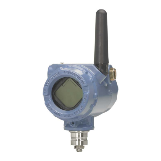
- Page 1 Quick Start Guide 00825-0200-4702, Rev GD June 2017 ™ Rosemount 702 Wireless Discrete Transmitter...
- Page 2 Quick Start Guide NOTICE This guide provides basic guidelines for the Rosemount 702. It does not provide instructions for detailed configuration, diagnostics, maintenance, service, troubleshooting, or installations. Refer to the Rosemount 702 Reference Manual (document number 00809-0200-4702) for more instruction. This guide and the manual are available electronically on www.rosemount.com.
-
Page 3: Wireless Considerations
Install the Black Power Module, SmartPower™ Solutions model number 701PBKKF (part number 00753-9220-0001) into the Rosemount 702 Transmitter to power the device. Wireless devices should be powered up in order of proximity from the Gateway, beginning with the closest device, then working outward from the Gateway. - Page 4 0020 P/N 00753-9200-0020 COMM The Rosemount 702 Transmitter and all other wireless devices should not be set up until after the Smart Wireless Gateway has been installed and is functioning properly. The Rosemount 702 Transmitter can be installed in one of two configurations: Direct mount, where the switch is connected directly to the Rosemount 702 ...
- Page 5 1. Install the switch according to standard installation practices making sure to use thread sealant on all connections. 2. Attach the Rosemount 702 Transmitter housing to the switch using the threaded conduit entry. 3. Attach the switch wiring to the terminals as indicated on the wiring diagram (Figures 12–...
-
Page 6: Remote Mount
1. Install the switch according to standard installation practices making sure to use thread sealant on all connections. 2. Run wiring (and conduit if necessary) from the switch to the Rosemount 702 Transmitter. 3. Pull the wiring through the threaded conduit entry of the Rosemount 702 Transmitter. - Page 7 Quick Start Guide June 2017 5. Connect the black power module. Note Wireless devices should be powered up in order of proximity from the Smart Wireless Gateway, beginning with the closest device to the gateway. This will result in a simpler and faster network installation.
- Page 8 Rosemount 702 Transmitter based on wireless connectivity, lightning protection, and current work practices. When installing remote mount antennas for the Rosemount 702 Transmitter, always use established safety procedures to avoid falling or contact with high-power electrical lines. Install remote antenna components for the Rosemount 702 Transmitter in compliance with local and national electrical codes and use best practices for lightning protection.
- Page 9 Note: Weatherproofing The remote mount antenna kit includes coaxial sealant for weatherproofing the cable connections for the lightning arrestor, antenna, and Rosemount 702 Transmitter. Coaxial sealant must be applied to guarantee performance of the wireless field network. See Figure 7 on page 9 for details on how to apply coaxial sealant.
- Page 10 Network ID and Join Key of the Gateway and other devices in the network. If the Network ID and Join Key do not match that of the Gateway, the Rosemount 702 Transmitter will not communicate with the network. The Network ID and Join Key may be obtained from the Smart Wireless Gateway on the Setup>Network>Settings page on the web interface, shown in...
- Page 11 There are four ways to verify operation: using the optional local display (LCD), using the Field Communicator, using the Smart Wireless Gateway’s integrated web interface, or by using AMS Suite Wireless Configurator. If the Rosemount 702 Transmitter was configured with the Network ID and Join Key, and sufficient time has passed, the transmitter will be connected to the network.
- Page 12 If the device joins the network and immediately has an alarm present, it is likely caused by the sensor configuration. Check the sensor wiring (see “Rosemount 702 Transmitter Terminal” on page 14) and the sensor configuration (see “Rosemount 702 Transmitter Fast Key Sequence” on page 27). Figure 9. Smart Wireless Gateway Explorer Page...
-
Page 13: Troubleshooting
Quick Start Guide June 2017 AMS Wireless Configurator When the device has joined the network, it will appear in AMS Wireless Configurator as illustrated below. Figure 10. AMS Wireless Configurator, Device Explorer Screen Troubleshooting If the device is not joined to the network after power up, verify the correct configuration of the Network ID and Join Key, and that Active Advertising has been enabled on the Smart Wireless Gateway. - Page 14 Reference information: wiring switch inputs, output circuits, and leak sensors Dry contact switch inputs The Rosemount 702 Transmitter has a pair of screw terminals for each of two channels, and a pair of communication terminals. These terminals are labeled as follows:...
- Page 15 FALSE (0.0) Dual input, limit contact logic When configured for Limit Contact Logic, the Rosemount 702 Transmitter will accept the input from two single pole single throw switch on inputs CH1 and CH2, and will use limit contact logic for the determination of the wireless outputs.
- Page 16 FAULT(NaN) Dual input, opposing contact logic When configured for Opposing Contact Logic, the Rosemount 702 Transmitter will accept the input from a double pole single throw switch on inputs CH1 and CH2, and will use opposing contact logic for the determination of the wireless outputs.
- Page 17 Count Variable reporting and mapping The Rosemount 702 Transmitter has two choices for variable reporting: Classic - Discrete State Only, or Enhanced – Discrete State and Count. In the Classic variable reporting mode, the Rosemount 702 Transmitter will report variables exactly like the previous version of the device (measurement option code 22).
- Page 18 Note The output switch functionality of the Rosemount 702 Transmitter requires that the network is managed by a version 4 Smart Wireless Gateway, with v4.3 or greater firmware installed.
- Page 19 Quick Start Guide June 2017 Figure 18. Output Circuit Wiring Figure 19. Possible Configurations for Both Channel 1 and Channel 2 Special considerations for dual output circuits If both channels are connected to output circuits, it is very important that the CMN terminal of each circuit be at the same voltage.
- Page 20 Quick Start Guide Figure 20. Dual Output Circuits with a Common Ground If two output circuits are connected to a single Rosemount 702 Transmitter with a single power supply, both CH + and CMN terminals must be connected to each output circuit.
- Page 21 Quick Start Guide June 2017 Figure 22. Wiring an Interposing Relay to Switch Greater Currents or Voltages Leak sensors, liquid hydrocarbon detection, measurement option code 61 Terminal block connections The Liquid Hydrocarbon Detection configuration is intended for use with the ®...
- Page 22 The Rosemount 702 Wireless Discrete Transmitter can support up to 3 Fast Fuel sensors. These Fast Fuel sensors are connected using TraceTek Modular Leader Cable (TT-MLC-MC-BLK), optional modular jumper cables (TT-MJC-xx-MC-BLK)
- Page 23 Tyco Thermo Controls, LLC The Rosemount 702 Wireless Discrete Transmitter can support up to 500 feet of TraceTek hydrocarbon or solvent sensor cable (TT5000 or TT5001 series). The total amount of sensor cable connected to a single Rosemount 702 Transmitter is not to exceed 500 ft.
- Page 24 June 2017 Quick Start Guide imperative that both PV and SV be mapped to the host system so as to make a good interpretation of the condition and status of the leak detector. NOTICE It is imperative that both PV and SV be mapped to the host system so the diagnostic information on the sensor status is captured.
- Page 25 TopWorx™, an Emerson company. These kits are ordered as a part of the Rosemount 702 model code, or separately as an accessory kit, and are available for both insulated and un-insulated pipes.
- Page 26 The switch can be re-set only by placing a ferrous metal object on the far side of the sensing area of the switch. Figure 29. TopWorx Switch Installed on an Eye Wash Station Field Communicator use Note In order to communicate with a Field Communicator, power the Rosemount 702 Transmitter by connecting the power module.
- Page 27 Quick Start Guide June 2017 Table 6. Rosemount 702 Transmitter Fast Key Sequence Fast Key Function Menu items sequence Manufacturer Model, Final Assembly Number, Universal, Field Device information 2, 2, 4, 3 Device, Software, Hardware, Descriptor, Message, Date, Model Number I, II, III, SI Unit Restriction, Country...
-
Page 28: Telecommunication Compliance
A copy of the EC Declaration of Conformity can be found at the end of the Quick Start Guide. The most recent revision of the EC Declaration of Conformity can be found at Emerson.com/Rosemount. Telecommunication compliance All wireless devices require certification to ensure that they adhere to regulations regarding the use of the RF spectrum. - Page 29 Markings: NI CL I, DIV 2, GP A, B, C, D T4; T4(-50 °C ≤ T ≤ +70 °C) when installed per Rosemount drawing 00702-1000; Type 4X/IP66 Special Condition for Safe Use (X): 1. For use only with the Rosemount 701P or Rosemount P/N 753-9220-XXXX Smart Power Battery Module. Canada CSA Intrinsically Safe Certificate: 1143113 Standards: CAN/CSA C22.2 No.
- Page 30 ≤ +70 °C) Ex ia IIC T4 Ga, Markings: T4(-60 °C ≤ T ≤ +40 °C) For use with Rosemount SmartPower power module part number 753-9220-0001, or for use with Emerson SmartPower option 701PBKKF. Sensor terminal parameters Fuel sensor terminal parameters...
- Page 31 2. The Rosemount 701PB Power Module may be replaced in a hazardous area. The power module has surface resistivity greater than 1 GΩ and must be properly installed in the wireless device enclosure.
- Page 32 3. The Rosemount 702 enclosure may be made of aluminum alloy and given a protective polyurethane paint finish; however, care should be taken to protect it from impact or abrasion if located in a Zone 0 area.
- Page 33 Quick Start Guide June 2017 Terminal parameters Sensor terminal Fuel sensor terminal (option code 42) parameters parameters (option code 32) (option code 61) Sensor Switch = 6.6 V = 26 V = 6.6 V = 7.8 V = 13.4 mA = 100 mA = 13.4 mA = 92 mA...
- Page 34 June 2017 Quick Start Guide Terminal parameters Sensor terminal Fuel sensor terminal (option code 42) parameters parameters (option code 32) (option code 61) Sensor Switch = 6.6 B , B = 26 B = 6.6 B = 7.8 B = 13.4 A = 100 = 13.4 = 92...
-
Page 35: Eu Declaration Of Conformity
Quick Start Guide June 2017 Figure 31. Rosemount 702 Declaration of Conformity EU Declaration of Conformity No: RMD 1066 Rev. N Rosemount, Inc. 8200 Market Boulevard Chanhassen, MN 55317-9685 declare under our sole responsibility that the product, Rosemount 702 Wireless Discrete Transmitter manufactured by, Rosemount, Inc. - Page 36 EN 301 489-17: V3.2.0 EN 61010-1: 2010 EN 62479: 2010 ATEX Directive (2014/34/EU) Rosemount 702 Wireless Discrete Transmitter (Options 22, 32, and 61) Baseefa07ATEX0239X – Intrinsic Safety Equipment Group II, Category 1 G Ex ia IIC T4/T5 Ga Ex ia I Ma...
- Page 37 Quick Start Guide June 2017 EU Declaration of Conformity No: RMD 1066 Rev. N ATEX Notified Body SGS Baseefa Limited [Notified Body Number: 1180] Rockhead Business Park, Staden Lane Buxton, Derbyshire SK179RZ United Kingdom ATEX Notified Body for Quality Assurance SGS Baseefa Limited [Notified Body Number: 1180] Rockhead Business Park, Staden Lane...
- Page 38 June 2017 Quick Start Guide Rosemount 702 China RoHS List of Parts with China RoHS Concentration above MCVs Rosemount 702 / Hazardous Substances Hexavalent Polybrominated Polybrominated Part Name Lead Mercury Cadmium Chromium biphenyls diphenyl ethers (Pb) (Hg) (Cd) (Cr +6)
- Page 39 Quick Start Guide June 2017...
- Page 40 The Emerson logo is a trademark and service mark of Emerson +65 6777 0947 Electric Co. Enquiries@AP.Emerson.com TopWorx, Go Switch, SmartPower, Rosemount, and Rosemount logotype are registered trademarks of Emerson. Middle East and Africa Regional Office HART and WirelessHART are registered trademarks of FieldComm Emerson Automation Solutions Group.
Need help?
Do you have a question about the 702 and is the answer not in the manual?
Questions and answers