
Subscribe to Our Youtube Channel
Related Manuals for Rosemount 2051CF Series


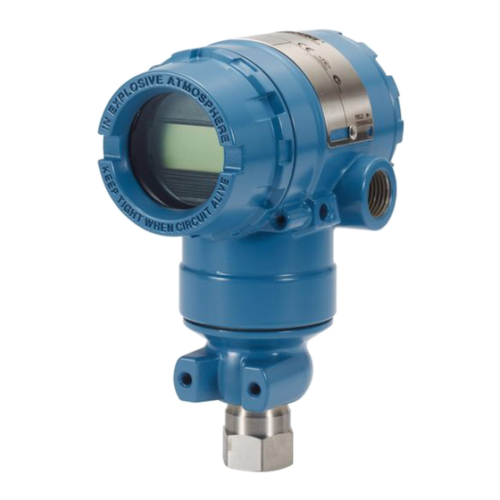
Summary of Contents for Rosemount 2051CF Series
- Page 1 Quick Start Guide 00825-0100-4107, Rev DC February 2019 ™ Rosemount 2051 Pressure Transmitter and Rosemount 2051CF Series Flowmeter ® with 4–20 mA HART and 1–5Vdc Low Power HART Protocol (Revision 5 and 7)
- Page 2 The products described in this document are NOT designed for nuclear-qualified applications. Using non-nuclear qualified products in applications that require nuclear-qualified hardware or products may cause inaccurate readings.For information on Rosemount nuclear-qualified products, contact your local Emerson Sales Representative. WARNING Explosions could result in death or serious injury.
-
Page 3: Table Of Contents
Contents System readiness........... 5 Verify configuration........19 Mount the transmitter........7 Trim the transmitter........23 Housing rotation..........14 Safety instrumented systems....... 26 ™ Set the switches........... 15 Rosemount 2051 Product Certifications..27 Connect the wiring and power up....16 Quick Start Guide... - Page 4 Quick Start Guide February 2019 Rosemount 2051 Pressure Transmitter Quick Start Guide...
-
Page 5: System Readiness
1.2.1 Rosemount 2051 device revisions and drivers Table 1-1 provides the information necessary to ensure you have the correct device driver and documentation for your device. Table 1-1: Rosemount 2051 Foundation Fieldbus Device Revisions and Files Device Host Device driver... - Page 6 Quick Start Guide February 2019 Table 1-1: Rosemount 2051 Foundation Fieldbus Device Revisions and Files (continued) Device Host Device driver Obtain at Device driver Manual Revision (DD) (DTM) Document Number DD4: DD Rev Fieldbus.org EmersonProce 00809-0200-4 ss.com 101, Rev AA...
-
Page 7: Mount The Transmitter
February 2019 Quick Start Guide Mount the transmitter Liquid applications Procedure 1. Place taps to the side of the line. 2. Mount beside or below the taps. 3. Mount the transmitter so the drain/vent valves are oriented upward. Gas applications Procedure 1. - Page 8 1. Place taps to the side of the line. 2. Mount beside or below the taps. 3. Fill impulse lines with water. Example Figure 2-1: Panel and Pipe Mounting Panel mount Pipe mount Coplanar flange Traditional flange Rosemount 2051 Pressure Transmitter Quick Start Guide...
- Page 9 February 2019 Quick Start Guide Rosemount 2051T × 1 panel bolts are customer supplied. Bolting considerations If the transmitter installation requires assembly of the process flanges, manifolds, or flange adapters, follow the assembly guidelines to ensure a tight seal for optimal performance characteristics of the transmitters. Use only ™...
- Page 10 3. Torque the bolts to the final torque value using the same crossing pattern. See Table 2-1 for final torque value. 4. Verify the flange bolts are protruding through the sensor module bolt holes before applying pressure. Rosemount 2051 Pressure Transmitter Quick Start Guide...
- Page 11 650 in-lb Stainless Steel (SST) 150 in-lb 300 in-lb O-rings The two styles of Rosemount flange adapters (Rosemount 1151 and Rosemount 3051/2051/2024/3095) each require a unique O-ring (see Figure 2-3). Use only the O-ring designed for the corresponding flange adapter. WARNING Failure to install proper flange adapter O-rings may cause process leaks, which can result in death or serious injury.
- Page 12 The low side pressure port (atmospheric reference) on the in-line gage transmitter is located in the neck of the transmitter, behind the housing. The vent path is 360° around the transmitter between the housing and sensor. (See Figure 2-4.) Rosemount 2051 Pressure Transmitter Quick Start Guide...
- Page 13 February 2019 Quick Start Guide Keep the vent path free of any obstruction, including but not limited to paint, dust, and lubrication by mounting the transmitter so fluids can drain away. Figure 2-4: In-line Gage Low Side Pressure Port A. Pressure port location Quick Start Guide...
-
Page 14: Housing Rotation
3. If the desired location cannot be achieved due to thread limit, rotate the housing counterclockwise to the desired location (up to 360° from thread limit). 4. Re-tighten the housing rotation set screw to no more than 7 in-lbs when desired location is reached. Rosemount 2051 Pressure Transmitter Quick Start Guide... -
Page 15: Set The Switches
February 2019 Quick Start Guide Set the switches Set alarm and security switch configuration before installation as shown in Figure 4-1. • The alarm switch sets the analog output alarm to high or low. • Default alarm is high. • The security switch allows ( ) or prevents ( ) any configuration of the transmitter. -
Page 16: Connect The Wiring And Power Up
5,000 ft. (1500 m) in length. If applicable, install wiring with a drip loop. Arrange the drip loop so the bottom is lower than the conduit connections and the transmitter housing. Rosemount 2051 Pressure Transmitter Quick Start Guide... - Page 17 Quick Start Guide CAUTION • Installation of the transient protection terminal block does not provide transient protection unless the Rosemount 2051HT case is properly grounded. • Do not run signal wiring in conduit or open trays with power wiring, or near heavy electrical equipment.
- Page 18 8. When the transmitter is properly wired, refer to Figure 5-2 for internal and external transient grounding locations. Note The Rosemount 2051HT polished 316 SST housing only provides ground termination inside the terminal compartment. Rosemount 2051 Pressure Transmitter Quick Start Guide...
-
Page 19: Verify Configuration
Field Communicator and LOI are included in this step. Verifying configuration with a Field Communicator A Rosemount 2051 DD must be installed on the Field Communicator to verify configuration. Fast Key sequences for the latest DD are shown in Table 6-1. - Page 20 To activate the LOI, push any button. LOI button functionality is shown on the bottom corners of the display. See Table 6-2 Figure 6-2 for button operation and menu information. Rosemount 2051 Pressure Transmitter Quick Start Guide...
- Page 21 February 2019 Quick Start Guide Figure 6-1: Internal and External LOI Buttons A. Internal buttons B. External buttons Table 6-2: LOI Button Operation Button Left SCROLL Right ENTER Quick Start Guide...
- Page 22 Switch HART Revision mode If the HART configuration tool is not capable of communicating with HART Revision 7, the Rosemount 2051 will load a generic menu with limited capability. The following procedures will switch the HART Revision mode from the generic menu: Procedure Manual Setup >...
-
Page 23: Trim The Transmitter
Note When performing a zero trim, ensure the equalization valve is open and all wet legs are filled to the correct level. CAUTION It is not recommended to zero an absolute transmitter, Rosemount 2051HTA model. Procedure Choose your trim procedure. - Page 24 To access the configuration buttons on an aluminum housing, loosen the screw on the top tag and slide the tag on the top of the transmitter. Figure 7-1: External or Rear/Terminal-Side Configuration Buttons Analog zero and Digital zero span Aluminum Polished 316 SST Rosemount 2051 Pressure Transmitter Quick Start Guide...
- Page 25 February 2019 Quick Start Guide A. Configuration buttons LOI buttons (option M4) only offer front facing buttons on SST housing (option 1). Options D4 and DZ can still be purchased for rear/terminal-side facing buttons. Use one of the following procedures to perform a zero trim: 7.2.1 Perform trim with LOI (option M4) Procedure 1.
-
Page 26: Safety Instrumented Systems
Quick Start Guide February 2019 Safety instrumented systems For safety certified installations, refer to the Rosemount 2051 Reference Manual for installation procedure and system requirements. Rosemount 2051 Pressure Transmitter Quick Start Guide... -
Page 27: Rosemount ™ 2051 Product Certifications
A copy of the EC Declaration of Conformity can be found at the end of the Quick Start Guide. The most recent revision of the EC Declaration of Conformity can be found at EmersonProcess.com/Rosemount. Ordinary Location Certification As standard, the transmitter has been examined and tested to determine that... - Page 28 Standards: FM Class 3600 – 2011, FM Class 3610 – 2010, FM Class 3611 – 2004, FM Class 3810 – 2005 Markings: IS CL I, DIV 1, GP A, B, C, D when connected per Rosemount drawing 02051-1009 (–50 °C ≤ T ≤ +60 °C); Type 4x...
- Page 29 February 2019 Quick Start Guide Europe E1 ATEX Flameproof Certificate: KEMA 08ATEX0090X Standards: EN60079-0:2006, EN60079-1:2007, EN60079-26:2007 Markings: II 1/2 G Ex d IIC T6 IP66 (–50 °C ≤ T ≤ 65 °C); II 1/2 G Ex d IIC T5 IP66 (–50 °C ≤T ≤...
- Page 30 1. If the equipment is fitted with an optional 90 V transient suppressor, it is incapable of withstanding the 500 V electrical strength test as defined in clause 6.5.1 of by EN 60079-15:2010. This must be taken into account during installation. ND ATEX Dust Certificate: Baseefa08ATEX0182X Rosemount 2051 Pressure Transmitter Quick Start Guide...
- Page 31 February 2019 Quick Start Guide Standards: EN60079-0:2012, EN60079-31:2009 Markings: II 1 D Ex ta IIIC T95 °C T 105 °C Da (–20 °C ≤ T ≤ +85 °C) Special Conditions for Safe Use (X): 1. If the equipment is fitted with an optional 90 V transient suppressor, it is incapable of withstanding the 500 V isolation from earth test and this must be taken into account during installation.
- Page 32 2. The enclosure may be made of aluminum alloy and given a protective polyurethane paint finish; however care should be taken to protect it from impact and abrasion when located in Zone 0. Rosemount 2051 Pressure Transmitter Quick Start Guide...
- Page 33 February 2019 Quick Start Guide N7 IECEx Type n Certificate: IECExBAS08.0046X Standards: IEC60079-0:2011, IEC60079-15:2010 Markings: Ex nA IIC T4 Gc (–40 °C ≤T ≤ +70 °C) Special Conditions for Safe Use (X): 1. If fitted with a 90 V transient suppressor, the equipment is not capable of withstanding the 500 V electrical strength test as defined in clause 6.5.1 of IEC60079-15:2010.
- Page 34 500 V insulation from earth test and this must be taken into account during installation. 2. The enclosure may be made of aluminium alloy and given a protective polyurethane paint finish; however care should be taken to protect it Rosemount 2051 Pressure Transmitter Quick Start Guide...
- Page 35 February 2019 Quick Start Guide from impact and abrasion when located in atmospheres that require ELP Ga. China E3 China Flameproof Certificate: GYJ13.1386X; GYJ15.1366X [Flowmeters] Standards: GB3836.1-2010, GB3836.2-2010, GB3836.20-2010-2010 Markings: Pressure Transmitter: Ex d IIC Gb, T6(–50 °C ≤ T ≤...
- Page 36 0 mH Note FISCO parameters comply with the requirements for FISCO field devices in GB3836.19-2010 [For Flowmeters] When Rosemount 644 Temperature Transmitter is used, the transmitter should be used with Ex-certified associated apparatus to establish explosion protection system that can be used in explosive gas atmospheres. Wiring and...
- Page 37 February 2019 Quick Start Guide Rosemount 644 and associated apparatus. The cables between Rosemount 644 and associated apparatus should be shielded cables (the cables must have insulated shield). The shielded cable has to be grounded reliably in a non-hazardous area.
- Page 38 SBS American Bureau of Shipping (ABS) Type Approval Certificate: 09-HS446883B-3-PDA Intended Use: Marine and Offshore Applications – Measurement of either Gauge or Absolute Pressure for Liquid, Gas, and Vapor. ABS Rules: 2013 Steel Vessels Rules 1-1-4/7.7, 1-1-Appendix 3, 4-8-3/1.7, 4-8-3/13.1 Rosemount 2051 Pressure Transmitter Quick Start Guide...
- Page 39 February 2019 Quick Start Guide SBV Bureau Veritas (BV) Type Approval Certificate: 23157/B0 BV BV Rules: Bureau Veritas Rules for the Classification of Steel Ships Application: Class notations: AUT-UMS, AUT-CCS, AUT-PORT and AUT-IMS; Pressure transmitter type 2051 cannot be installed on diesel engines SDN Det Norske Veritas (DNV) Type Approval Certificate:...
- Page 40 Quick Start Guide February 2019 Figure 9-1: Rosemount 2051 Declaration of Conformity EU Declaration of Conformity No: RMD 1071 Rev. M Rosemount, Inc. 8200 Market Boulevard Chanhassen, MN 55317-9685 declare under our sole responsibility that the product, Rosemount™ Model 2051 Pressure Transmitter manufactured by, Rosemount, Inc.
- Page 41 No: RMD 1071 Rev. M EMC Directive (2014/30/EU) Harmonized Standards: EN 61326-1:2013, EN 61326-2-3:2013 PED Directive (2014/68/EU) Rosemount 2051CD2, 3, 4, 5 (also with P9 option) Certificate No. 12698-2018-CE-ACCREDIA QS Certificate of Assessment - Module H Conformity Assessment Other Standards Used: ANSI / ISA 61010-1:2004 Note –...
- Page 42 P.O. Box 30 (Särkiniementie 3) 00211 HELSINKI Finland ATEX Notified Body for Quality Assurance SGS FIMCO OY [Notified Body Number: 0598] P.O. Box 30 (Särkiniementie 3) 00211 HELSINKI Finland Page 3 of 3 Rosemount 2051 Pressure Transmitter Quick Start Guide...
- Page 43 February 2019 Quick Start Guide Quick Start Guide...
- Page 44 The Emerson logo is a Facebook.com/Rosemount trademark and service mark of Emerson Electric Youtube.com/user/ Co. Rosemount is mark of one of the Emerson RosemountMeasurement family of companies. All other marks are the Google.com/+RosemountMeasurement property of their respective owners.
Need help?
Do you have a question about the 2051CF Series and is the answer not in the manual?
Questions and answers