
Related Manuals for Rosemount 8732


Summary of Contents for Rosemount 8732
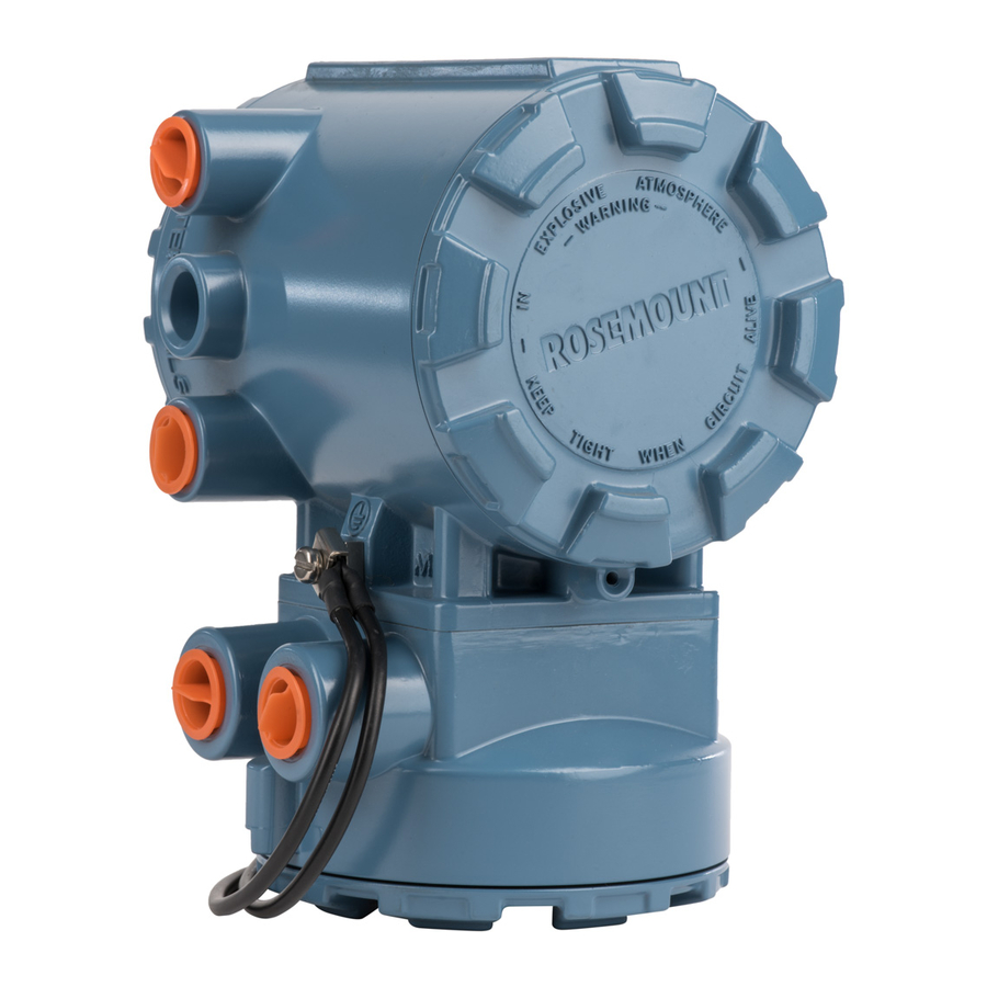
- Page 1 Reference Manual 00809-0100-4663, Rev BA January 2010 Rosemount 8732 Integral Mount or Remote Mount Magnetic ™ Flowmeter System with F fieldbus OUNDATION www.rosemount.com...
- Page 3 The products described in this document are NOT designed for nuclear-qualified applications. Using non-nuclear qualified products in applications that require nuclear-qualified hardware or products may cause inaccurate readings. For information on Rosemount nuclear-qualified products, contact your local Rosemount Sales Representative. www.rosemount.com...
-
Page 5: Table Of Contents
Rosemount Sensors ........ - Page 6 Reference Manual 00809-0100-4663, Rev BA Rosemount 8732 January 2010 Basic Setup ..........3-7 Tag .
- Page 7 Diagnostics Licensing the 8732 Diagnostics ......C-2 Tunable Empty Pipe Detection ......C-2 Tunable Empty Pipe Parameters .
- Page 8 8732 Transmitter ........E-13...
- Page 9 Reference Manual 00809-0100-4663, Rev BA Rosemount 8732 January 2010 APPENDIX F Definition..........F-1 Parameters and Descriptions .
- Page 10 Reference Manual 00809-0100-4663, Rev BA Rosemount 8732 January 2010 TOC-6...
-
Page 11: System Description
The transmitter can be integrally or remotely mounted from the sensor. This manual is designed to assist in the installation and operation of the Rosemount 8732 Magnetic Flowmeter Transmitter and the Rosemount 8700 Series Magnetic Flowmeter Sensors. www.rosemount.com... -
Page 12: Safety Messages
Attempting to install and operate the Rosemount 8705, 8707 High-Signal, 8711 or 8721 Magnetic Sensors with the Rosemount 8712 or 8732 Magnetic Flowmeter Transmitter without reviewing the instructions contained in this manual could result in personal injury or equipment damage. -
Page 13: Safety Messages
Do not connect a Rosemount 8732 to a non-Rosemount sensor that is located in an explosive atmosphere. Explosions could result in death or serious injury: Installation of this transmitter in an explosive environment must be in accordance with the appropriate local, national, and international standards, codes, and practices. -
Page 14: Transmitter Symbols
LOI screen (see Figure 2-1). The transmitter should be mounted in a manner that prevents moisture in conduit from collecting in the transmitter. If the 8732 is mounted remotely from the sensor, it is not subject to limitations that might apply to the sensor. -
Page 15: Environmental Considerations
Remote-mounted transmitters may be installed in the control room to protect the electronics from a harsh environment and provides easy access for configuration or service. Rosemount 8732 transmitters require external power so there must be access to a suitable power source. INSTALLATION Rosemount 8732 installation includes both detailed mechanical and electrical installation procedures. -
Page 16: Identify Options And Configurations
Transmitter Security The security switch on the 8732 allows the user to lock out any configuration changes attempted on the transmitter. No changes to the configuration are allowed when the switch is in the ON position. The flow rate indication function remains active at all times. -
Page 17: Conduit Ports And Connections
Remove display if applicable. Identify the location of each switch (see Figure 2-2). Change the setting of the desired switches with a small screwdriver. Replace the electronics cover. Figure 2-2. Rosemount 8732 Electronics Board and Hardware Switches Conduit Ports and... -
Page 18: Conduit Cables
Transmitter Input Power The 8732 transmitter is designed to be powered by 90-250 V AC, 50–60 Hz or 12–42 V DC. The eighth digit in the transmitter model number designates the appropriate power supply requirement. -
Page 19: Installation Category
I = Supply current requirement (Amps) V = Power supply voltage (Volts) Installation Category The installation category for the Rosemount 8732 is (overvoltage) Category II. Overcurrent Protection The Rosemount 8732 Flowmeter Transmitter requires overcurrent protection of the supply lines. Maximum ratings of overcurrent devices are as follows:... -
Page 20: Connect Foundation
Reference Manual 00809-0100-4663, Rev BA Rosemount 8732 January 2010 Figure 2-5. AC Transmitter Power Connections AC Line or DC + AC Neutral or DC – Transmitter Power Cable AC or DC Ground Connect F The F fieldbus signal provides the output information from the... -
Page 21: Transmitter Wiring Connection
OUNDATION Connect -FF to Terminal 1. Connect +FF to Terminal 2. NOTE Foundation fieldbus signal wiring for the 8732 is not polarity sensitive. Refer to Figure 2-6 on page 2-9. Figure 2-6. F fieldbus OUNDATION... - Page 22 Reference Manual 00809-0100-4663, Rev BA Rosemount 8732 January 2010 Figure 2-7. Rosemount 8732 Transmitter Field Wiring 6234 ft (1900 m) max (depending upon cable characteristics) Integrated Power Conditioner Terminators and Filter Fieldbus Segment Power Supply (Trunk) (The power supply, filter, first terminator,...
-
Page 23: Sensor Connections
This section covers the steps required to physically install the transmitter including wiring and calibration. Rosemount Sensors To connect the transmitter to a non-Rosemount sensor, refer to the appropriate wiring diagram in “Universal Sensor Wiring Diagrams” on page E-1. The calibration procedure listed is not required for use with Rosemount sensors. -
Page 24: Conduit Cables
00809-0100-4663, Rev BA Rosemount 8732 January 2010 Rosemount recommends using the combination signal and coil drive for N5, E5 approved sensors for optimum performance. Remote transmitter installations require equal lengths of signal and coil drive cables. Integrally mounted transmitters are factory wired and do not require interconnecting cables. -
Page 25: Sensor To Remote Mount Transmitter Connections
Connect coil drive and electrode cables as shown in Figure 2-10. Transmitter Connections Do not connect AC power to the sensor or to terminals 1 and 2 of the transmitter, or replacement of the electronics board will be necessary. Figure 2-10. Wiring Diagram Rosemount 8705/8707/8711/8721 Rosemount 8732 Transmitter Sensors 2-13... - Page 26 Reference Manual 00809-0100-4663, Rev BA Rosemount 8732 January 2010 2-14...
-
Page 27: Introduction
3-6 LOCAL OPERATOR The optional Local Operator Interface (LOI) provides an operator communications center for the 8732. By using the LOI, the operator can INTERFACE access any transmitter function for changing configuration parameter settings, checking totalized values, or other functions. The LOI is integral to the transmitter electronics. -
Page 28: Data Entry
Reference Manual 00809-0100-4663, Rev BA Rosemount 8732 January 2010 Figure 3-1. Local Operator Interface Keypad Data Entry The LOI keypad does not have numerical keys. Numerical data is entered by the following procedure. Access the appropriate function. Use the RIGHT ARROW key to move to the value to change. -
Page 29: Select Value Example
Reference Manual 00809-0100-4663, Rev BA Rosemount 8732 January 2010 Table Value Example Setting the TUBE SIZE: Press the DOWN arrow to access the menu. Select line size from the Basic set-up menu. Press the UP or DOWN arrow to increase/decrease (incrementally) the tube size to the next value. - Page 30 Reference Manual 00809-0100-4663, Rev BA Rosemount 8732 January 2010 Table 3-2. LOI Menu Tree Diagnostics Diag Controls Empty Pipe B asic Diag Process Noise Self Test Advanced Diag Ground/Wiring Ground/Wiring R un 8714i AO L oop Test V ariables Elec Temp...
-
Page 31: Diagnostic Messages
• 4-20 mA Loop Verification Failed • 8714i Failed Review The 8732 includes a capability that enables you to review the configuration variable settings. Fast Keys 1, 5 The flowmeter configuration parameters set at the factory should be reviewed to ensure accuracy and compatibility with your particular application of the flowmeter. -
Page 32: Pv - Primary Variable
Reference Manual 00809-0100-4663, Rev BA Rosemount 8732 January 2010 Analog Output – The analog output variable provides the analog value for the flow rate. The analog output refers to the industry standard output in the 4–20 mA range. The analog output and 4-20 mA loop can be verified using the Analog Feedback diagnostic capability internal to the transmitter (See “8714i... -
Page 33: Pulse Output
The Pulse Output displays the current value of the pulse signal. Fast Keys 1, 1, 5 BASIC SETUP The basic configuration functions of the Rosemount 8732 must be set for all applications of the transmitter in a magnetic flowmeter system. If your Fast Keys 1, 3 application requires the advanced functionality features of the Rosemount 8732, see Section 4 "Operation"... - Page 34 (see “Flow Units” on page 3-7). If your application has special needs and the standard configurations do not apply, the Rosemount 8732 provides the flexibility to configure the transmitter in a custom-designed units format using the special units variable.
-
Page 35: Line Size
The actual special units setting you define will not appear. Four characters are available to store the new units designation. The 8732 LOI will display the four character designation as configured. -
Page 36: Pv Urv (Upper Range Value)
Reference Manual 00809-0100-4663, Rev BA Rosemount 8732 January 2010 PV URV The upper range value (URV), or analog output range, is preset to 30 ft/s at the factory. The units that appear will be the same as those selected under the (Upper Range Value) units parameter. -
Page 37: Calibration Number
Be sure the calibration number reflects a calibration to a Rosemount reference transmitter. If the calibration number was generated by a means other than a certified Rosemount flow lab, accuracy of the system may be compromised. If your flowtube sensor is not a Rosemount flowtube sensor and was not calibrated at the Rosemount factory, contact your Rosemount representative for assistance. - Page 38 Reference Manual 00809-0100-4663, Rev BA Rosemount 8732 January 2010 3-12...
-
Page 39: Introduction
This section contains information for advanced configuration parameters and diagnostics. The software configuration settings for the Rosemount 8732 can be accessed through a 375 Field Communicator or through a control system. The software functions for the 375 Field Communicator are described in detail in this section of the manual. -
Page 40: Basic Diagnostics
Reference Manual 00809-0100-4663, Rev BA Rosemount 8732 January 2010 Empty Pipe Detection Turn the empty pipe diagnostic on or off as required by the application. For more details on the empty pipe diagnostic, see Appendix C: Diagnostics. Electronics Temperature Out of Range Turn the electronics temperature diagnostic on or off as required by the application. -
Page 41: Advanced Diagnostics
Advanced Diagnostics The advanced diagnostics menu contains information on all of the additional diagnostics and tests that are available in the 8732 transmitter if one of the 375 Transducer Block, Diagnostics diagnostics suite packages was ordered. Rosemount offers two advanced diagnostic suites. Functionality under this menu will depend on which of these suites are ordered. - Page 42 Reference Manual 00809-0100-4663, Rev BA Rosemount 8732 January 2010 8714i Results 375 Transducer Block, Diagnostics, Advanced Diagnostics, 8714i Meter Verification Review the results of the most recently performed 8714i Meter Verification test. Information in this section details the measurements taken and if the meter passed the verification test.
- Page 43 Reference Manual 00809-0100-4663, Rev BA Rosemount 8732 January 2010 Sensor Calibration Result 375 Transducer Block, Diagnostics, Advanced Diagnostics, 8714i Meter Verification, 8714i Results Displays the result of the sensor calibration verification test as pass or fail. For more details on this parameter see Appendix C: Diagnostics.
- Page 44 Have the transmitter measure and store the sensor signature values. These values will then be used as the baseline for the meter verification test. Use this when connecting to older Rosemount or competitors’ sensors or installing the magnetic flowmeter system for the first time. For more details on this parameter see Appendix C: Diagnostics.
- Page 45 Reference Manual 00809-0100-4663, Rev BA Rosemount 8732 January 2010 Measurements 375 Transducer Block, Diagnostics, Advanced Diagnostics, 8714i Meter Verification View the measured values taken during the meter verification process. These values are compared to the signature values to determine if the test passes or fails.
-
Page 46: Diagnostic Variables
Reference Manual 00809-0100-4663, Rev BA Rosemount 8732 January 2010 Diagnostic Variables From this menu, all of the diagnostic variable values can be reviewed. This information can be used to get more information about the transmitter, sensor, 375 Transducer Block, Diagnostics and process, or to get more detail about an alert that may have activated. -
Page 47: Trims
Reference Manual 00809-0100-4663, Rev BA Rosemount 8732 January 2010 8714i Result 375 Transducer Block, Diagnostics, Diagnostic Variables, 8714i Results Displays the results of the 8714i Meter Verification test as pass or fail. For more details on this parameter see Appendix C: Diagnostics. - Page 48 If this message occurs, no values were changed in the transmitter. Simply power down the Rosemount 8732E to clear the message. To simulate a nominal sensor with the Rosemount 8714, you must change the following five parameters in the Rosemount 8732E: Sensor Calibration Number—1000015010000000...
-
Page 49: Status
375 Transducer Block, Diagnostics, Trims The universal auto trim function enables the Rosemount 8732E to calibrate sensors that were not calibrated at the Rosemount factory. The function is activated as one step in a procedure known as in-process calibration. If your Rosemount sensor has a 16-digit calibration number, in-process calibration is not required. -
Page 50: Advanced Configuration
Rosemount 8732 January 2010 ADVANCED In addition to the basic configuration options and the diagnostic information and controls, the 8732 has many advanced functions that can also be CONFIGURATION configured as required by the application. DETAILED SETUP The detailed setup function provides access to other parameters within the... -
Page 51: Display Language
Reference Manual 00809-0100-4663, Rev BA Rosemount 8732 January 2010 Cal Min Span 375 Transducer Block, Detailed Setup, Additional Params The PV minimum span is the minimum flow range that must separate the minimum and maximum configured PV Range values. Reverse Flow 375 Transducer Block, Detailed Setup, Additional Params Enable or disable the transmitter’s ability to read reverse flow. - Page 52 Control 375 Transducer Block, Detailed Setup, Signal Processing, Man Config DSP When ON is selected, the Rosemount 8732E output is derived using a running average of the individual flow inputs. Signal processing is a software algorithm that examines the quality of the electrode signal against user-specified tolerances.
-
Page 53: Device Info
Reference Manual 00809-0100-4663, Rev BA Rosemount 8732 January 2010 For example, if the number of samples selected is 100, then the response time of the system is 10 seconds. In some cases this may be unacceptable. By setting the time limit, you can force the 8732E to clear the value of the running average and re-establish the output and average at the new flow rate once the time limit has elapsed. - Page 54 Reference Manual 00809-0100-4663, Rev BA Rosemount 8732 January 2010 Sensor Tag 375 Transducer Block, Detailed Setup, Device Info Sensor tag is the quickest and shortest way of identifying and distinguishing between sensors. Sensors can be tagged according to the requirements of your application.
-
Page 55: Mode
Reference Manual 00809-0100-4663, Rev BA Rosemount 8732 January 2010 Electrode Type 375 Transducer Block, Detailed Setup, Device Info, Construction Materials Electrode type enables you to select the electrode type for your magnetic transmitter system. This variable only needs to be changed if you have replaced electrodes or if you have replaced your sensor. -
Page 56: Block Mode: Target
Reference Manual 00809-0100-4663, Rev BA Rosemount 8732 January 2010 Block Mode: Target Operator requested mode for the function block. Only one selection may be made. Options include: Transducer Block, Mode Auto Use this mode when all configuration changes to the block are complete and the transmitter is ready to be returned to service. -
Page 57: Safety Messages
Verify that the operating environment of the sensor and transmitter is consistent with the appropriate hazardous area approval. Do not connect a Rosemount 8732 to a non-Rosemount sensor that is located in an explosive atmosphere. www.rosemount.com... - Page 58 Installation of this transmitter in an explosive environment must be in accordance with the appropriate local, national, and international standards, codes, and practices. Please review the approvals section of the 8732 reference manual for any restrictions associated with a safe installation.
-
Page 59: Sensor Handling
Figure 5-1 shows sensors correctly supported for handling and installation. Notice the plywood end pieces are still in place to protect the sensor liner during transportation. Figure 5-1. Rosemount 8705 Sensor Support for Handling 6-Inch and Larger ½- through 4-Inch... -
Page 60: Sensor Mounting
Reference Manual 00809-0100-4663, Rev BA Rosemount 8732 January 2010 SENSOR MOUNTING Physical mounting of a sensor is similar to installing a typical section of pipe. Conventional tools, equipment, and accessories (bolts, gaskets, and grounding hardware) are required. Upstream/Downstream To ensure specification accuracy over widely varying process conditions,... - Page 61 Reference Manual 00809-0100-4663, Rev BA Rosemount 8732 January 2010 Figure 5-4. Incline or Decline Orientation FLOW FLOW Horizontal installation should be restricted to low piping sections that are normally full. Orient the electrode plane to within 45 degrees of horizontal in horizontal installations.
-
Page 62: Flow Direction
Rosemount 8732 January 2010 The electrodes in the Rosemount 8711 are properly oriented when the top of the sensor is either vertical or horizontal, as shown in Figure 5-6. Avoid any mounting orientation that positions the top of the sensor at 45 degrees from the vertical or horizontal position. -
Page 63: Installation (Flanged Sensor)
The following section should be used as a guide in the installation of the flange-type Rosemount 8705 and Rosemount 8707 High-Signal Sensors. (FLANGED SENSOR) Refer to page 5-10 for installation of the wafer-type Rosemount 8711 Sensor. Gaskets The sensor requires a gasket at each of its connections to adjacent devices or piping. - Page 64 All sensors require a second torquing 24 hours after initial flange bolt tightening. Table 5-1. Flange Bolt Torque Specifications for Rosemount 8705 and 8707 High-Signal Sensors PTFE/ETFE liner Polyurethane liner Class 150...
- Page 65 Reference Manual 00809-0100-4663, Rev BA Rosemount 8732 January 2010 Table 5-2. Flange Bolt Torque and Bolt Load Specifications for Rosemount 8705 PTFE/ETFE liner PN10 PN 16 PN 25 PN 40 Size Code Line Size (Newton-meter) (Newton) (Newton-meter) (Newton) (Newton-meter) (Newton) (Newton-meter) (Newton)
-
Page 66: Installation (Wafer Sensor)
Reference Manual 00809-0100-4663, Rev BA Rosemount 8732 January 2010 Table 5-3. Flange Bolt Torque and Bolt Load Specifications for Rosemount 8705 Polyurethane Liner PN 10 PN 16 PN 25 PN 40 Size Code Line Size (Newton-meter) (Newton) (Newton-meter) (Newton) (Newton-meter) (Newton) (Newton-meter) (Newton) -
Page 67: Flange Bolts
Reference Manual 00809-0100-4663, Rev BA Rosemount 8732 January 2010 Table 5-4. Stud Specifications Nominal Sensor Size Stud Specifications 0.15 – 1 inch (4 – 25 mm) 316 SST ASTM A193, Grade B8M Class 1 threaded mounted studs – 8 inch (40 – 200 mm) CS, ASTM A193, Grade B7, threaded mounting studs Place the sensor between the flanges. -
Page 68: Installation (Sanitary Sensor)
The sensor requires a gasket at each of its connections to adjacent devices or piping. The gasket material selected must be compatible with the process fluid and operating conditions. Gaskets are supplied with all Rosemount 8721 Sanitary sensors except when the process connection is an IDF sanitary screw type. -
Page 69: Grounding
Reference Manual 00809-0100-4663, Rev BA Rosemount 8732 January 2010 NOTE Consult factory for installations requiring cathodic protection or situations where there are high currents or high potential in the process. The sensor case should always be earth grounded in accordance with national and local electrical codes. - Page 70 Reference Manual 00809-0100-4663, Rev BA Rosemount 8732 January 2010 Figure 5-14. Grounding with Grounding Rings or Lining Protectors Grounding Rings or Lining Protectors Figure 5-15. Grounding with Grounding Rings or Lining Protectors Grounding Rings or Lining Protectors 5-14...
- Page 71 Reference Manual 00809-0100-4663, Rev BA Rosemount 8732 January 2010 Figure 5-16. Grounding with Grounding Electrodes 5-15...
-
Page 72: Process Leak Protection (Optional)
00809-0100-4663, Rev BA Rosemount 8732 January 2010 PROCESS LEAK The Rosemount 8705 and 8707 High-Signal Sensor housing is fabricated from carbon steel to perform two separate functions. First, it provides PROTECTION shielding for the sensor magnetics so that external disturbances cannot (OPTIONAL) interfere with the magnetic field and thus affect the flow measurement. -
Page 73: Relief Valves
Reference Manual 00809-0100-4663, Rev BA Rosemount 8732 January 2010 Relief Valves The first optional configuration, identified by the W1 in the model number option code, uses a completely welded coil housing. This configuration does not provide separate electrode compartments with external electrode access. - Page 74 Reference Manual 00809-0100-4663, Rev BA Rosemount 8732 January 2010 Figure 5-19. Housing Configuration — Sealed Electrode Compartment (Option Code W3) Fused Glass Seal O-Ring Seal Sealed Electrode Compartment - 27 NPT Optional: Use drain port to plumb to a safe area...
-
Page 75: Safety Information
FM or CSA approval. Do not connect a Rosemount 8732 to a non-Rosemount sensor that is located in an explosive atmosphere. Mishandling products exposed to a hazardous substance may result in death or serious injury. -
Page 76: Installation Check And Guide
Reference Manual 00809-0100-4663, Rev BA Rosemount 8732 January 2010 INSTALLATION CHECK Use this guide to check new installations of Rosemount magnetic flowmeter systems that appear to malfunction. AND GUIDE Before You Begin Transmitter Apply power to your system before making the following transmitter checks. -
Page 77: Diagnostic Messages
Problems in the magnetic flowmeter system are usually indicated by incorrect output readings from the system, error messages, or failed tests. Consider all MESSAGES sources in identifying a problem in your system. Table 6-1. Rosemount 8732 Basic Diagnostic Messages Message Potential Cause Corrective Action “Fieldbus Not... - Page 78 Reference Manual 00809-0100-4663, Rev BA Rosemount 8732 January 2010 Table 6-2. Rosemount 8732 Advanced Diagnostic Messages (Suite 1 - Option Code D01) Message Potential Cause Corrective Action Grounding/Wiring Fault Improper installation of wiring See “Sensor Connections” on page 2-11 Coil/Electrode shield not See “Sensor Connections”...
-
Page 79: Transmitter Troubleshooting
Reference Manual 00809-0100-4663, Rev BA Rosemount 8732 January 2010 TRANSMITTER TROUBLESHOOTING Table 6-4. Advanced Troubleshooting–Rosemount 8732 Symptom Potential Cause Corrective Action Does not appear to be within Transmitter, control system, or other Check all configuration variables for the transmitter, sensor,... - Page 80 Sensor calibration number Units Line size Electrode coating Use bulletnose electrodes in the Rosemount 8705 Sensor. Downsize the sensor to increase the flow rate above 3 ft/s. Periodically clean the sensor Air in line Move the sensor to another location in the process line to...
-
Page 81: Quick Troubleshooting
To interpret the results, the hazardous location certification for the sensor must be known. Applicable codes for the Rosemount 8705 are N0, N5, and KD. Applicable codes for the Rosemount 8707 are N0 and N5. Applicable codes for the Rosemount 8711 are N0, N5, E5, and KD. - Page 82 Reference Manual 00809-0100-4663, Rev BA Rosemount 8732 January 2010 Table 6-5. Sensor Test Sensor Required Measuring at Test Location Equipment Connections Expected Value Potential Cause Corrective Action A. Sensor Installed or Multimeter 1 and 2 = R 2...
-
Page 83: Step 4: Uninstalled Sensor Tests
Sensor Tests be known. Applicable codes for the Rosemount 8705 are N0, N5, and KD. Applicable codes for the Rosemount 8707 are N0 and N5. Applicable codes for the Rosemount 8711 are N0, N5, E5, and KD. - Page 84 Measure both electrodes. One electrode should result in an open reading, while the other electrode should be less than 275 Table 6-7. Uninstalled Rosemount 8711 Wafer Sensor Tests Hazardous Location Certification Measuring at Connections N5, E5, CD 18 and Electrode ...
-
Page 85: Functional Specifications
FUNCTIONAL Sensor Compatibility SPECIFICATIONS Compatible with Rosemount 8705, 8711, 8721, and 570TM sensors. Compatible with Rosemount 8707 sensor with D2 Dual calibration option. Compatible with AC and DC powered sensors of other manufacturers. Sensor Coil Resistance 350 maximum Flow Rate Range Capable of processing signals from fluids that are traveling between 0.04 and... - Page 86 Reference Manual 00809-0100-4663, Rev BA Rosemount 8732 January 2010 Figure A-2. Apparent Power Power Supply Voltage (AC RMS) DC Supply Current Requirements Units powered by 12-42 V DC power supply may draw up to 1 amp of current steady state.
- Page 87 Reference Manual 00809-0100-4663, Rev BA Rosemount 8732 January 2010 Enclosure Rating NEMA 4X CSA Type 4X, IEC 60529, IP66 (transmitter), Pollution Degree 2 Output Signal Manchester-encoded digital signal that conforms to IEC 1158-2 and ISA 50.02...
-
Page 88: Foundation Fieldbus Specifications
Damping Adjustable between 0 and 256 seconds. Sensor Compensation Rosemount sensors are flow-calibrated and assigned a calibration factor at the factory. The calibration factor is entered into the transmitter, enabling interchangeability of sensors without calculations or a compromise in standard accuracy. -
Page 89: Performance Specifications
January 2010 8732E transmitters and other manufacturer’s sensors can be calibrated at known process conditions or at the Rosemount NIST-Traceable Flow Facility. Transmitters calibrated on site require a two-step procedure to match a known flow rate. This procedure can be found in “Universal Trim” on page 4-11. - Page 90 0.04 and 3.0 ft/s (0.01 and 1 m/s), the system has an accuracy of ±0.015 ft/s (0.005 m/s). Rosemount 8732E with Other Manufacturers’ Sensors: When calibrated in the Rosemount Flow Facility, system accuracies as good as 0.5% of rate can be attained. There is no accuracy specification for other manufacturers’ sensors calibrated in the process line.
-
Page 91: Physical Specifications
Reference Manual 00809-0100-4663, Rev BA Rosemount 8732 January 2010 Stability ±0.1% of rate over six months Ambient Temperature Effect ±0.25% change over operating temperature range EMC Compliance EN61326-1 1997 + A1/A2/A3 (Industrial) electromagnetic compatibility (EMC) for process and laboratory apparatus. - Page 92 Reference Manual 00809-0100-4663, Rev BA Rosemount 8732 January 2010...
-
Page 93: Product Certifications
Emerson Process Management Flow Technologies Co., Ltd. — Nanjing, China European Directive Information The EC declaration of conformity for all applicable European directives for this product can be found on our website at www.rosemount.com. A hard copy may be obtained by contacting our local sales office. ATEX Directive Rosemount Inc. -
Page 94: Electro Magnetic Compatibility (Emc) (2004/108/Ec
Compliance with all applicable European Union Directives. (Note: CE Marking is not available on Rosemount 8712H). IECEx Scheme For Rosemount 8732E transmitters: Rosemount complies with all of the stated standards below: IEC 60079-0 : 2004 IEC 60079-1 : 2007-04 IEC 60079-11 : 2006... -
Page 95: Hazardous Locations Product Approvals Offering
Reference Manual 00809-0100-4663, Rev BA Rosemount 8732 January 2010 HAZARDOUS The Rosemount 8700 Series magnetic flowmeters offer many different hazardous locations certifications. The table below provides an overview of LOCATIONS PRODUCT the available hazardous area approval options. Equivalent hazardous APPROVALS OFFERING locations certifications for sensor and transmitter must match in integrally mounted magnetic flowmeter systems. - Page 96 Reference Manual 00809-0100-4663, Rev BA Rosemount 8732 January 2010 Table B-3. ATEX Approvals Transmitter 8732E 8712D 8712H Offering Sensor 8705 8707 8711 8705 8707 8711 8707 ATEX Category Hazardous Area Approval Code Non-Hazardous Trans: LVD and EMC Sensor: LVD and EMC...
-
Page 97: Hazardous Location Certifications
Reference Manual 00809-0100-4663, Rev BA Rosemount 8732 January 2010 Equipment Category 1 - Dust Environment Dust Environment Only Trans: Dust Ignition Proof Other Certifications Product Certification Code European Pressure Equipment Directive (PED) NSF 61 Drinking Water (1) Available in remote mount configuration only. Requires equivalent ATEX approval on the sensor (2) For I.S. - Page 98 Reference Rosemount Control Drawing 08732-1051 (8732E) Class I, Division 2, Groups A, B, C, D Temp Codes – T4 (8732 at 60°C: -50 °C Ta 60 °C) Dust-ignition proof Class II/III, Division 1, Groups E, F, G Temp Codes – T4 (8712 at 40°C), T5 (8732 at 60°C)
- Page 99 The electrical data is to be taken from Table B-7 on page B-12 If the Rosemount 8732 Flow Transmitter is used integrally with the Junction Box, it shall be assured that the mechanical contact areas of the Junction Box and Flow Transmitter comply with the requirements for flanged joints according to standard EN/IEC 60079-1 clause 5.2.
- Page 100 90 °C. A Junction Box in type of explosion protection increased safety “e” may be attached to the base of the Rosemount 8732E Flow Transmitter, permitting remote mounting of the Rosemount 8705 and 8711 Sensors.
- Page 101 The electrical data is to be taken from Table B-7 on page B-12 If the Rosemount 8732 Flow Transmitter is used integrally with the Junction Box, it shall be assured that the mechanical contact areas of the Junction Box and Flow Transmitter comply with the requirements for flanged joints according to standard EN/IEC 60079-1 clause 5.2.
- Page 102 CE Marking; 3-A Symbol Authorization #1222; EHEDG Type EL European Certifications ATEX Dust 8732 - Certificate No.: KEMA 06ATEX0006 II 1D max T = 40 °K(1) Amb. Temp. Limits: (-20 °C = Ta = +65 °C) Vmax = 40 V DC (pulsed)
- Page 103 = 40 V DC (pulsed) SPECIAL CONDITIONS FOR SAFE USE (X): If the Rosemount 8732 Flow Transmitter is used integrally with the Rosemount 8705 or Rosemount 8711 Sensors, it shall be assured that the mechanical contact areas of the Sensor and Flow Transmitter comply with the requirements for flat joints according to standard EN 50018, clause 5.2.
- Page 104 00809-0100-4663, Rev BA Rosemount 8732 January 2010 Table B-7. Electrical Data Rosemount 8732 Flow Transmitter Power supply: 250 V AC, 1 A or 42 Vdc, 2,5 A, 20 W maximum Foundation fieldbus 30 V DC, 30 mA, 1 W maximum...
- Page 105 Reference Manual 00809-0100-4663, Rev BA Rosemount 8732 January 2010 Table B-8. Relation between Maximum Process Temperature ambient temperature, process Meter Size (Inches) Maximum Ambient Temperature Temperature Class temperature, and temperature 115°F (65°C) 239°F (115°C) class 149°F (65°C) 248°F (120°C) 95°F (35°C) 95°F (35°C)
- Page 106 Reference Manual 00809-0100-4663, Rev BA Rosemount 8732 January 2010 Maximum process temperature °F (°C) per temperature class Maximum Ambient Temperature 1.5 in. sensor size 149°F (65°C) 297°F (147°C) 160°F (71°C) 88°F (31°C) 55°F (13°C) 140°F (60°C) 307°F (153°C) 171°F (77°C) 97°F (36°C)
- Page 107 Reference Manual 00809-0100-4663, Rev BA Rosemount 8732 January 2010 Figure B-1. ATEX Installation (1 of 6) B-15...
- Page 108 Reference Manual 00809-0100-4663, Rev BA Rosemount 8732 January 2010 Figure B-2. ATEX Installation (2 of 6) B-16...
- Page 109 Reference Manual 00809-0100-4663, Rev BA Rosemount 8732 January 2010 Figure B-3. ATEX Installation (3 of 6) B-17...
- Page 110 Reference Manual 00809-0100-4663, Rev BA Rosemount 8732 January 2010 Figure B-4. ATEX Installation (4 of 6) B-18...
- Page 111 Reference Manual 00809-0100-4663, Rev BA Rosemount 8732 January 2010 Figure B-5. ATEX Installation (5 of 6) B-19...
- Page 112 Reference Manual 00809-0100-4663, Rev BA Rosemount 8732 January 2010 Figure B-6. ATEX Installation (6 of 6) B-20...
- Page 113 Reference Manual 00809-0100-4663, Rev BA Rosemount 8732 January 2010 Figure B-7. FM Certified I.S. Output (1 of 4) B-21...
- Page 114 Reference Manual 00809-0100-4663, Rev BA Rosemount 8732 January 2010 Figure B-8. FM Certified I.S. Output (2 of 4) B-22...
- Page 115 Reference Manual 00809-0100-4663, Rev BA Rosemount 8732 January 2010 Figure B-9. FM Certified I.S. Output (3 of 4) B-23...
- Page 116 Reference Manual 00809-0100-4663, Rev BA Rosemount 8732 January 2010 Figure B-10. FM Certified I.S. Output (4 of 4) B-24...
- Page 117 Reference Manual 00809-0100-4663, Rev BA Rosemount 8732 January 2010 Figure B-11. CSA Certified I.S. Output (1 of 2) B-25...
- Page 118 Reference Manual 00809-0100-4663, Rev BA Rosemount 8732 January 2010 Figure B-12. CSA Certified I.S. Output (2 of 2) B-26...
- Page 119 Reference Manual 00809-0100-4663, Rev BA Rosemount 8732 January 2010 Figure B-13. CSA Installation B-27...
- Page 120 Reference Manual 00809-0100-4663, Rev BA Rosemount 8732 January 2010 Figure B-14. Factory Mutual Hazardous Locations B-28...
-
Page 121: Diagnostic Availability
D02 Option 8714i Meter Verification Meter Verification • Options for Accessing Diagnostics Rosemount Magmeter Diagnostics can be accessed through the 375 Field Communicator, AMS Device Manager, or any other F fieldbus OUNDATION configuration tool. Access Diagnostics through AMS Intelligent Device Manager for the Ultimate Value The value of the Diagnostics increases significantly when AMS is used. -
Page 122: Licensing And Enabling
ENABLING diagnostics can be licensed in the field through the use of a license key. To obtain a license key, contact your local Rosemount Representative. Each transmitter has a unique license key specific to the diagnostic option code. See the detailed procedures below for entering the license key and enabling the advanced diagnostics. -
Page 123: Optimizing Tunable Empty Pipe
Reference Manual 00809-0100-4663, Rev BA Rosemount 8732 January 2010 Empty Pipe Value Transducer Block, Diagnostics, Basic Diagnostics, Empty Pipe Limits, EP Value AMS Tab Diagnostics Reads the current Empty Pipe Value. This is a read-only value. This number is a unitless number and is calculated based on multiple installation and process variables such as sensor type, line size, process fluid properties, and wiring. -
Page 124: Troubleshooting Empty Pipe
Reference Manual 00809-0100-4663, Rev BA Rosemount 8732 January 2010 Troubleshooting Empty The following actions can be taken if Empty Pipe detection is unexpected. Pipe Verify the sensor is full. Verify that the sensor has not been installed with a measurement electrode at the top of the pipe. -
Page 125: Troubleshooting Ground/Wiring Fault
Reference Manual 00809-0100-4663, Rev BA Rosemount 8732 January 2010 Troubleshooting The transmitter detected high levels of 50/60 Hz noise caused by improper wiring or poor process grounding. Ground/Wiring Fault Verify that the transmitter is earth grounded. Connect ground rings, grounding electrode, lining protector, or grounding straps. -
Page 126: High Process Noise Parameters
Reference Manual 00809-0100-4663, Rev BA Rosemount 8732 January 2010 High Process Noise The High Process Noise diagnostic has two read-only parameters. It does not have any configurable parameters. This diagnostic requires that flow be Parameters present in the pipe and the velocity be > 1 ft/s. -
Page 127: High Process Noise Functionality
Rosemount High-Signal 8707 sensor be used. These sensors can be calibrated to run at lower coil drive current supplied by the standard Rosemount transmitters, but can also be upgraded by changing to the 8712H High-Signal transmitter. -
Page 128: 8714I Meter Verification
Reference Manual 00809-0100-4663, Rev BA Rosemount 8732 January 2010 The transmitter continuously monitors signal amplitudes over a wide range of frequencies. For the high process noise diagnostic, the transmitter specifically looks at the signal amplitude at frequencies of 2.5 Hz, 7.5 Hz, 32.5 Hz, and 42.5 Hz. -
Page 129: 8714I Meter Verification Test Parameters
Reference Manual 00809-0100-4663, Rev BA Rosemount 8732 January 2010 8714i Meter Verification The 8714i has a multitude of parameters that set the test criteria, test conditions, and scope of the calibration verification test. Test Parameters Test Conditions for the 8714i Meter Verification There are three possible test conditions that the 8714i Meter Verification test can be initiated under. -
Page 130: 8714I Meter Verification Test Results Parameters
Reference Manual 00809-0100-4663, Rev BA Rosemount 8732 January 2010 Empty Pipe Set the test criteria for the Empty Pipe condition. The factory default for this value is set to three percent with limits configurable between one and ten percent. Transducer Block, Diagnostics, Advanced Diagnostics, 8714i Meter Verification,... - Page 131 Reference Manual 00809-0100-4663, Rev BA Rosemount 8732 January 2010 Viewing the 8714i Meter Verification Results Depending on the method used to view the results, they will be displayed in either a menu structure, as a method, or in the report format. When using the 375 Field Communicator, each individual component can be viewed as a menu item.
- Page 132 Reference Manual 00809-0100-4663, Rev BA Rosemount 8732 January 2010 Actual Velocity Displays the velocity measured by the transmitter during the transmitter calibration verification process. Transducer Block, Diagnostics, Advanced Diagnostics, 8714i Meter Verification, 8714i Results, Actual Velocity AMS Tab Context Menu, Device Diagnostics, 8714i Report...
-
Page 133: Optimizing The 8714I Meter Verification
Reference Manual 00809-0100-4663, Rev BA Rosemount 8732 January 2010 Optimizing the 8714i The 8714i Meter Verification diagnostic can be optimized by setting the test criteria to the desired levels necessary to meet the compliance requirements Meter Verification of the application. The following examples below will provide some guidance on how to set these levels. -
Page 134: Troubleshooting The 8714I Meter Verification Test
Reference Manual 00809-0100-4663, Rev BA Rosemount 8732 January 2010 Troubleshooting the In the event that the 8714i Meter Verification test fails, the following steps can be used to determine the appropriate course of action. Begin by reviewing the 8714i Meter Verification 8714i results to determine the specific test that failed. - Page 135 Reference Manual 00809-0100-4663, Rev BA Rosemount 8732 January 2010 Electrode Circuit Resistance The Electrode Circuit Resistance is a measurement of the electrode circuit health. This value is used as a baseline to determine if the electrode circuit is still operating correctly when the 8714i Meter Verification diagnostic is initiated.
-
Page 136: Rosemount Magnetic Flowmeter Calibration Verification Report
Reference Manual 00809-0100-4663, Rev BA Rosemount 8732 January 2010 ROSEMOUNT MAGNETIC FLOWMETER CALIBRATION VERIFICATION REPORT Calibration Verification Report Parameters Calibration Conditions: □ Internal □ External User Name: _____________________________________________ Test Conditions: □ Flowing □ No Flow, Full Pipe □ Empty Pipe... -
Page 137: Safety Messages
Reference Manual 00809-0100-4663, Rev BA Rosemount 8732 January 2010 Appendix D Digital Signal Processing Safety Messages ....... . . page D-1 Procedures . -
Page 138: Procedures
00809-0100-4663, Rev BA Rosemount 8732 January 2010 PROCEDURES If the output of your Rosemount 8732 is unstable, first check the wiring and grounding associated with the magnetic flowmeter system. Ensure that the following conditions are met: • Ground straps are attached to the adjacent flange or ground ring? •... - Page 139 Reference Manual 00809-0100-4663, Rev BA Rosemount 8732 January 2010 This software technique, known as signal processing, “qualifies” individual flow signals based on historic flow information and three user-definable parameters, plus an on/off control. These parameters are: Number of samples: The number of samples function sets the amount of time that inputs are collected and used to calculate the average value.
- Page 140 When Should Signal Processing Be Used? The Rosemount 8732 offers three separate functions that can be used in series for improving a noisy output. The first step is to toggle the coil drive to the 37 Hz mode and initialize with an auto zero.
- Page 141 Diagrams Rosemount Sensors ......page E-3 Brooks Sensors ....... . . page E-6 Endress And Hauser Sensors .
- Page 142 00809-0100-4663, Rev BA Rosemount 8732 January 2010 Table E-1. Sensor Cross References Rosemount Transmitter Sensor Manufacturer Page Number Rosemount Rosemount 8732 Rosemount 8705, 8707, 8711 page E-3 Rosemount 8732 Rosemount 8701 page E-4 Brooks Rosemount 8732 Model 5000 page E-6 Rosemount 8732...
-
Page 143: Rosemount Sensors
Rosemount Connect coil drive and electrode cables as shown in Figure . 8705/8707/8711/8721 Sensors to Rosemount 8732 Transmitter Figure E-1. Wiring Diagram to a Rosemount 8732 Transmitter Table E-2. Rosemount 8705/8707/8711/8721 Sensor Rosemount 8732 Transmitters Rosemount 8705/8707/8711/8721 Sensors Wiring Connections This is a pulsed DC magnetic flowmeter. -
Page 144: Rosemount 8701 Sensor To Rosemount 8732 Transmitter
00809-0100-4663, Rev BA Rosemount 8732 January 2010 Rosemount 8701 Sensor Connect coil drive and electrode cables as shown in Figure E-2 on page E-4. to Rosemount 8732 Transmitter Figure E-2. Wiring Diagram for Rosemount 8701 Sensor and Rosemount 8732 Transmitter... -
Page 145: Connecting Sensors Of Other Manufacturers
Verify that the sensor coil is configured for series connection. Other manufacturers sensors may be wired in either a series or parallel circuit. All Rosemount magnetic sensors are wired in a series circuit. (Other manufacturers AC sensors (AC coils) wired for 220V operation are typically wired in parallel and must be rewired in series.) -
Page 146: Brooks Sensors
Reference Manual 00809-0100-4663, Rev BA Rosemount 8732 January 2010 BROOKS SENSORS Connect coil drive and electrode cables as shown in Figure E-3. Model 5000 Sensor to Rosemount 8732 Transmitter Figure E-3. Wiring Diagram for Brooks Sensor Model 5000 and BROOKS MODEL... -
Page 147: Model 7400 Sensor To Rosemount 8732 Transmitter
Reference Manual 00809-0100-4663, Rev BA Rosemount 8732 January 2010 Model 7400 Sensor to Connect coil drive and electrode cables as shown in Figure E-4. Rosemount 8732 Transmitter Figure E-4. Wiring Diagram for Brooks Sensor Model 7400 and BROOKS MODEL 7400... -
Page 148: Endress And Hauser Sensors
SENSORS Endress and Hauser Sensor to Rosemount 8732 Transmitter Figure E-5. Wiring Diagram for Endress and Hauser Sensors ROSEMOUNT 8732 and Rosemount 8732 TRANSMITTER ENDRESS AND HAUSER SENSORS Coils Electrodes Table E-6. Endress and Hauser Sensor Wiring Connections Rosemount 8732 Endress and Hauser Sensors This is a pulsed DC magnetic flowmeter. -
Page 149: Fischer And Porter Sensors
Rosemount 8732 January 2010 FISCHER AND PORTER Connect coil drive and electrode cables as shown in Figure E-6. SENSORS Model 10D1418 Sensor to Rosemount 8732 Transmitter Figure E-6. Wiring Diagram for Fischer and Porter Sensor Model 10D1418 and Rosemount 8732... -
Page 150: Model 10D1419 Sensor To Rosemount 8732 Transmitter
Reference Manual 00809-0100-4663, Rev BA Rosemount 8732 January 2010 Model 10D1419 Sensor Connect coil drive and electrode cables as shown in Figure E-7. to Rosemount 8732 Transmitter Figure E-7. Wiring Diagram for Fischer and Porter Sensor Model 10D1419 and Rosemount 8732... -
Page 151: Model 10D1430 Sensor (Remote) To Rosemount 8732 Transmitter
Rosemount 8732 Transmitter Figure E-8. Wiring Diagram for Fischer and Porter Sensor Model 10D1430 (Remote) and Rosemount 8732 ROSEMOUNT 8732 TRANSMITTER Electrode Connections Coil Connections Table E-9. Fischer and Porter Model 10D1430 (Remote) Fischer and Porter Model 10D1430 (Remote) Sensor Wiring Connections... -
Page 152: Model 10D1430 Sensor (Integral) To Rosemount 8732 Transmitter
(Integral) to Rosemount 8732 Transmitter Figure E-9. Wiring Diagram for Fischer and Porter Sensor Model 10D1430 (Integral) and Rosemount 8732 ROSEMOUNT 8732 TRANSMITTER Electrode Connections To L2 Coil Connections To Calibration Device (Disconnect) Table E-10. Fischer and Porter Model 10D1430 (Integral) -
Page 153: Model 10D1465 And Model 10D1475 Sensors (Integral) To 8732 Transmitter
Rosemount 8732 January 2010 Model 10D1465 and Connect coil drive and electrode cables as shown in Figure E-10. Model 10D1475 Sensors (Integral) to 8732 Transmitter Figure E-10. Wiring Diagram for Fischer and Porter Sensor Model 10D1465 and Model 10D1475 (Integral) and... -
Page 154: Fischer And Porter Sensor To Rosemount 8732 Transmitter
Fischer and Porter Connect coil drive and electrode cables as shown in Figure E-11. Sensor to Rosemount 8732 Transmitter Figure E-11. Generic Wiring Diagram for Fischer and Porter Sensors and Rosemount 8732 ROSEMOUNT 8732 FISCHER AND PORTER TRANSMITTER SENSORS Electrodes Coils... -
Page 155: Foxboro Sensors
Reference Manual 00809-0100-4663, Rev BA Rosemount 8732 January 2010 FOXBORO SENSORS Connect coil drive and electrode cables as shown in Figure E-12. Series 1800 Sensor to Rosemount 8732 Transmitter Figure E-12. Wiring Diagram for Foxboro Series 1800 and Rosemount 8732... -
Page 156: Series 1800 (Version 2) Sensor To Rosemount 8732 Transmitter
Series 1800 (Version 2) Connect coil drive and electrode cables as shown in Figure E-13. Sensor to Rosemount 8732 Transmitter Figure E-13. Wiring Diagram for Foxboro Series 1800 (Version 2) and Rosemount 8732 FOXBORO SERIES ROSEMOUNT 1800 SENSOR 8732 (VERSION 2) TRANSMITTER... -
Page 157: Series 2800 Sensor To 8732 Transmitter
Reference Manual 00809-0100-4663, Rev BA Rosemount 8732 January 2010 Series 2800 Sensor to Connect coil drive and electrode cables as shown in Figure E-14. 8732 Transmitter Figure E-14. Wiring Diagram for Foxboro Series 2800 and FOXBORO SERIES ROSEMOUNT 8732 Rosemount 8732... -
Page 158: Foxboro Sensor To 8732 Transmitter
Reference Manual 00809-0100-4663, Rev BA Rosemount 8732 January 2010 Foxboro Sensor to 8732 Connect coil drive and electrode cables as shown in Figure E-15. Transmitter Figure E-15. Generic Wiring Diagram for Foxboro Sensors ROSEMOUNT 8732 FOXBORO and Rosemount 8732 TRANSMITTER... -
Page 159: Kent Veriflux Vtc Sensor
Reference Manual 00809-0100-4663, Rev BA Rosemount 8732 January 2010 KENT VERIFLUX VTC Connect coil drive and electrode cables as shown in Figure E-16. SENSOR Veriflux VTC Sensor to 8732 Transmitter Figure E-16. Wiring Diagram for Kent Veriflux VTC Sensor and... -
Page 160: Kent Sensors
Reference Manual 00809-0100-4663, Rev BA Rosemount 8732 January 2010 KENT SENSORS Connect coil drive and electrode cables as shown in Figure E-17. Kent Sensor to Rosemount 8732 Transmitter Figure E-17. Generic Wiring Diagram for Kent Sensors and KENT SENSORS ROSEMOUNT 8732... -
Page 161: Krohne Sensors
Connect coil drive and electrode cables as shown in Figure E-18. Krohne Sensor to Rosemount 8732 Transmitter Figure E-18. Generic Wiring ROSEMOUNT 8732 Diagram for Krohne Sensors KROHNE TRANSMITTER and Rosemount 8732 SENSORS Electrodes Electrode Shield Coil Shield Coils Fuse Table E-19. Krohne Sensor Wiring Connections... -
Page 162: Taylor Sensors
Reference Manual 00809-0100-4663, Rev BA Rosemount 8732 January 2010 TAYLOR SENSORS Connect coil drive and electrode cables as shown in Figure E-19. Series 1100 Sensor to Rosemount 8732 Transmitter Figure E-19. Wiring Diagram for Taylor Series 1100 Sensors and Rosemount 8732... -
Page 163: Taylor Sensor To Rosemount 8732 Transmitter
Reference Manual 00809-0100-4663, Rev BA Rosemount 8732 January 2010 Taylor Sensor to Connect coil drive and electrode cables as shown in Figure E-20. Rosemount 8732 Transmitter Figure E-20. Generic Wiring Diagram for Taylor Sensors and TAYLOR ROSEMOUNT 8732 Rosemount 8732... -
Page 164: Yamatake Honeywell Sensors
Reference Manual 00809-0100-4663, Rev BA Rosemount 8732 January 2010 YAMATAKE Connect coil drive and electrode cables as shown in Figure E-21. HONEYWELL SENSORS Yamatake Honeywell Sensor to Rosemount 8732 Transmitter Figure E-21. Generic Wiring Diagram for Yamatake ROSEMOUNT 8732 YAMATAKE... -
Page 165: Yokogawa Sensors
Connect coil drive and electrode cables as shown in Figure E-22. Yokogawa Sensor to Rosemount 8732 Transmitter Figure E-22. Generic Wiring Diagram for Yokogawa Sensors ROSEMOUNT 8732 YOKOGAWA and Rosemount 8732 TRANSMITTER SENSORS Electrodes Chassis Ground Ex 2 Coils Ex 1 Fuse Table E-23. -
Page 166: Generic Manufacturer Sensors
Connect the electrode terminals to Rosemount 8732 terminals 18 and 19. The electrode shield should be connected to terminal 17. Connect the coil terminals to Rosemount 8732 terminals 1, 2, and If the Rosemount 8732 Transmitter indicates a reverse flow condition, switch the coil wires connected to terminals 1 and 2. - Page 167 This parameter shows the current alert status, unacknowledged states, unreported states, and disabled states of the alarms associated with the function block. In the Rosemount 8732 Magnetic Flowmeter Transmitter, the two resource block alarms are write alarm and block alarm.
- Page 168 FEATURES This parameter is used to show supported resource block options. FEATURE_SEL Used to show selected resource block options. The Rosemount 8732 Magnetic Flowmeter Transmitter supports the following options: Unicode: Tells the host to use unicode for string values Reports: Enables alarms; must be set for alarming to work Software Lock: Software write locking enabled but not active;...
- Page 169 (not used by the device). HARD_TYPES HARD_TYPES shows the types of hardware available as channel numbers. For the Rosemount 8732, this parameter is limited to scalar (i.e., analog) inputs. HARDWARE_REV This parameter represents the hardware revision of the hardware that has the resource block in it.
- Page 170 Reference Manual 00809-0100-4663, Rev BA Rosemount 8732 January 2010 Index Number Parameter Rev 5 Description RESTART Allows a manual restart to be initiated. Several degrees of restart are possible: 1 Run: Nominal state when not restarting 2 Restart resource: Not used 3 Restart with defaults: Set parameters to default values (see START_WITH_DEFAULTS below for which parameters are set).
-
Page 171: Resource Block Errors
Reference Manual 00809-0100-4663, Rev BA Rosemount 8732 January 2010 RESOURCE BLOCK Table F-2 lists conditions reported in the BLOCK_ERR parameter. Conditions in italics are inactive for the resource block and are given here only for ERRORS your reference. Table F-2. Resource... -
Page 172: Alarm Detection
Reference Manual 00809-0100-4663, Rev BA Rosemount 8732 January 2010 Alarm Detection A block alarm will be generated whenever the BLOCK_ERR has an error bit set. The types of block error for the resource block are defined in Table F-2. A write alarm is generated whenever the WRITE_LOCK parameter is cleared. -
Page 173: Definition
The transducer block contains the actual flow measurement data. This data includes information about sensor type, engineering units, digital filter settings, damping, and diagnostics. Only a single channel is defined in the Rosemount 8732. Channel 1 provides flow measurements to the analog input (AI) block. www.rosemount.com... - Page 174 Reference Manual 00809-0100-4663, Rev BA Rosemount 8732 January 2010 PARAMETERS AND Table G-1 lists all of the configurable parameters of the transducer block, indicating the descriptions and index numbers for each parameters. DESCRIPTIONS Table G-1. Transducer Block Parameters Parameter Index Number...
-
Page 175: Flow-Specific Block Configuration Values
Reference Manual 00809-0100-4663, Rev BA Rosemount 8732 January 2010 FLOW-SPECIFIC BLOCK Once the transmitter is installed and communication is established, configuration must be completed. Three parameters must be entered for CONFIGURATION proper configuration: VALUES • Sensor calibration number • Engineering units (configured via AI block) •... -
Page 176: Transducer Block Errors
Reference Manual 00809-0100-4663, Rev BA Rosemount 8732 January 2010 TRANSDUCER BLOCK The following conditions are reported in the BLOCK_ERR and XD_ERROR parameters. Conditions in italics are inactive for the transducer block and are ERRORS given here only for your reference. -
Page 177: Transducer Block Diagnostics
Reference Manual 00809-0100-4663, Rev BA Rosemount 8732 January 2010 TRANSDUCER BLOCK In addition to the BLOCK_ERR and XD_ERROR parameters, more detailed information on the measurement status can be obtained via DIAGNOSTICS DETAILED_STATUS. Table G-5 lists the potential errors and the possible corrective actions for the given values. -
Page 178: Troubleshooting
Reference Manual 00809-0100-4663, Rev BA Rosemount 8732 January 2010 In Auto mode, OUT reflects the value and status quality of the output channels. TROUBLESHOOTING Refer to Table G-6 to troubleshoot transducer block problems. Table G-6. Troubleshooting Symptom Possible Causes Corrective Action... -
Page 179: Handheld Communicator
Reference Manual 00809-0100-4663, Rev BA Rosemount 8732 January 2010 Appendix H 375 Field Communicator Operation HandHeld Communicator ......page H-1 Connections and Hardware . -
Page 180: Connections And Hardware
Reference Manual 00809-0100-4663, Rev BA Rosemount 8732 January 2010 CONNECTIONS AND The 375 Field Communicator exchanges information with the transmitter from the control room, the instrument site, or any wiring termination point in the HARDWARE loop. Be sure to install the instruments in the loop in accordance with intrinsically safe or non-incendive field wiring practices. -
Page 181: Basic Features
OUNDATION If a F fieldbus compatible device is found, the communicator OUNDATION displays the Online Menu with device ID (8732) and tag (TRANSMITTER). Page Bksp Delete Page Directional Keys Use these keys to move the cursor up, down, left, or right. -
Page 182: Alphanumeric And Shift Keys
Reference Manual 00809-0100-4663, Rev BA Rosemount 8732 January 2010 Function Key Use the four software-defined function keys, located below the LCD, to perform software functions. On any given menu, the label appearing above a function key indicates the function of that key for the current menu. -
Page 183: Main Menu
Reference Manual 00809-0100-4663, Rev BA Rosemount 8732 January 2010 Main Menu The Main Menu provides the following options: • Offline - The Offline option provides access to offline configuration data and simulation functions. • Online - The Online option checks for a device and if it finds one, brings up the Online Menu. -
Page 184: Diagnostic Messages
Reference Manual 00809-0100-4663, Rev BA Rosemount 8732 January 2010 Diagnostic Messages The following is a list of messages used by the Handheld Communicator (HC) and their corresponding descriptions. Variable parameters within the text of a message are indicated with <variable parameter>. - Page 185 Reference Manual 00809-0100-4663, Rev BA Rosemount 8732 January 2010 Table H-1. Handheld Communicator Diagnostic Messages Message Description OFF KEY DISABLED Appears when the user attempts to turn the HC off before sending modified data or before completing a method On-line device disconnected with unsent data – RETRY or OK to There is unsent data for a previously connected device.
- Page 186 Reference Manual 00809-0100-4663, Rev BA Rosemount 8732 January 2010...
- Page 187 Reference Manual 00809-0100-4663, Rev BA Rosemount 8732 January 2010 Index ... . . 5-7 Action Keys Flange Bolts Handheld Communicator . H-3 ..H-3...
- Page 188 Reference Manual 00809-0100-4663, Rev BA Rosemount 8732 January 2010 . . 3-10 Lower Range Value (LRV) Specifications and Reference Data Wiring Diagrams ..E-6 Functional Specifications Brooks Model 5000 Overrange Capability Endress and Hauser Models ....2-4...
- Page 190 The Emerson logo is a trade mark and service mark of Emerson Electric Co. Rosemount and the Rosemount logotype are registered trademarks of Rosemount Inc. PlantWeb is a registered trademark of one of the Emerson Process Management group of companies.
Need help?
Do you have a question about the 8732 and is the answer not in the manual?
Questions and answers