
Related Manuals for Rosemount Oxymitter 5000


Summary of Contents for Rosemount Oxymitter 5000
- Page 1 Instruction Manual IM-106-350C, Rev 2.2 July 2008 Oxymitter 5000 Hazardous Area Oxygen Transmitter http://www.raihome.com...
- Page 3 Page 1-7 Removed step 6 under System Features from Rev 1.6. Page 1-10 Added Figure 1-7, Typical System Installation – Oxymitter 5000 with Remote Electronics. Page 1-11 Added Mounting and Operation instructions for the SPS 4001B. Page 1-14 thru 1-15 Updated the specifications table and added applicable certifications regarding the Hazardous Area Oxymitter 5000.
- Page 4 Pages 3-6 thru 3-8 in Section 3, Startup and Operation of Rev 1.4 was moved to Section 5, Startup and Operation of Oxymitter 5000 with Membrane Keypad. Page 6-1 thru 6-10 Added Section 6, Startup and Operation of Hazardous Area Oxymitter 5000 with LOI. Page 7-1 Added body text under Overview.
- Page 5 HIGHLIGHTS OF CHANGES (CONTINUED) Effective January 2007 Rev 2.1 (Continued) Page Summary Page 11-2 Added Asset Management Solutions (AMS) information. Page A-2 thru A-24 Added note 11 to the safety data section. Added new language translations. Page B-1 Updated the return of materials address. Back cover Updated the address blocks.
-
Page 7: Table Of Contents
Symbols ..........ii Oxymitter 5000 with Fieldbus Communications....iii SECTION 1 Component Checklist. - Page 8 LOI Installation......... . . 6-9 Oxymitter 5000 Test Points ....... . . 6-9 SECTION 7 Overview .
- Page 9 Instruction Manual IM-106-350C, Rev 2.2 Hazardous Area Oxymitter 5000 July 2008 Fuse Replacement ........9-14 Entire Probe Replacement (Excluding Electronics) .
- Page 10 Instruction Manual IM-106-350C, Rev 2.2 Hazardous Area Oxymitter 5000 July 2008 Feedforward Calculation ........E-6 Tracking .
-
Page 11: Essential Instructions
The following instructions MUST be adhered to and integrated into your safety program when installing, using, and maintaining Rosemount Analytical products. Failure to follow the proper instructions may cause any one of the following situations to occur: Loss of life;... -
Page 12: Preface
July 2008 PREFACE The purpose of this manual is to provide information concerning the components, functions, installation and maintenance of the Oxymitter 5000 Hazardous Area Oxygen Transmitter. Some sections may describe equipment not used in your configuration. The user should become thoroughly familiar with the operation of this module before operating it. -
Page 13: Oxymitter 5000 With Fieldbus Communications
For information on Fisher-Rosemount nuclear-qualified products, contact your local Fisher-Rosemount Sales Representative. Rosemount Analytical is a registered trademark of Rosemount Analytical Inc. Delta V, the Delta V logotype, PlantWeb, and PlantWeb logotype are trademarks of Fisher-Rosemount. - Page 14 Instruction Manual IM-106-350C, Rev 2.2 Hazardous Area Oxymitter 5000 July 2008...
-
Page 15: Component Checklist
The Oxymitter 5000 is offered in both hazardous area and general purpose configurations. The hazardous area version has special markings on the approval label. The general purpose does not. - Page 16 4. SPS 4001B Single Probe Autocalibration Sequencer (Optional) (Safe area only) 5. Mounting Plate with Mounting Hardware and Gasket 6. Hazardous Area Oxymitter 5000 with Remote Electronics (Optional) 7. Reference Air Set (used if SPS 4001B without reference air option or IMPS 4000 not supplied)
-
Page 17: Foundation Fieldbus Technology
• Speed options for process control and manufacturing applications System Description The Hazardous Area Oxymitter 5000 is designed to measure the net concentration of oxygen in an industrial process; i.e., the oxygen remaining after all fuels have been oxidized. The probe is permanently positioned within an exhaust duct or stack and performs its task without the use of a sampling system. -
Page 18: System Configuration
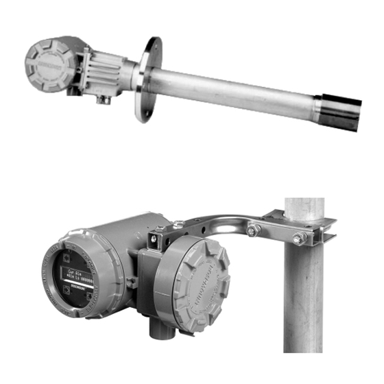
System Configuration Hazardous Area Oxymitter 5000 units are available in three length options, giving the user the flexibility to use an in situ penetration appropriate to the size of the stack or duct. The options on length are 457 mm (18 in.), 0.91 m (3 ft), and 1.83 m (6 ft). -
Page 19: System Features
Sequencer can be used with each Hazardous Area Oxymitter 5000 to provide automatic calibration gas sequencing. The sequencer performs autocalibrations based on the CALIBRATION RECOMMENDED signal from the Hazardous Area Oxymitter 5000, a timed interval set up in fieldbus, or whenever a calibration request is initiated. System Features 1. - Page 20 Instruction Manual IM-106-350C, Rev 2.2 Hazardous Area Oxymitter 5000 July 2008 Figure 1-3. Membrane Keypad HEATER T/C HEATER DIAGNOSTIC 02 CELL ALARMS CALIBRATION CALIBRATION RECOMMENDED 02 CELL mV + 02 CELL mv - TEST HEATER T/C + POINTS HEATER T/C -...
-
Page 21: Handling The Oxymitter
It is important that printed circuit boards and integrated circuits are handled only when adequate antistatic precautions have been taken to prevent possible equipment damage. The Hazardous Area Oxymitter 5000 is designed for industrial applications. Treat each component of the system with care to avoid physical damage. Some probe components are made from ceramics, which are susceptible to shock when mishandled. - Page 22 Figure 1-6. A typical system installation with remote electronics is illustrated in Figure 1-7. A source of instrument air is optional at the Hazardous Area Oxymitter 5000 for reference air use. Since the unit can be equipped with an in-place calibration feature, provisions can be made to permanently connect calibration gas bottles to the Hazardous Area Oxymitter 5000.
- Page 23 Instruction Manual IM-106-350C, Rev 2.2 Hazardous Area Oxymitter 5000 July 2008 Figure 1-6. Typical System Installation – Oxymitter 5000 with Integral Electronics STANDARD Gases Duct Stack Oxymitter Adapter 5000 Plate Line Voltage Instrument Air Supply (Reference Air) Logic I/O Pressure...
- Page 24 Instruction Manual IM-106-350C, Rev 2.2 Hazardous Area Oxymitter 5000 July 2008 Figure 1-7. Typical System Installation – Oxymitter 5000 with Remote Electronics STANDARD Gases Duct Stack Oxymitter 5000 Adapter Plate Flowmeter Remote Instrument Electronics Air Supply (Reference Air) Pressure Regulator...
-
Page 25: Imps 4000 (Optional)
Hazardous Area Oxymitter 5000 July 2008 IMPS 4000 (OPTIONAL) If using an IMPS 4000 with a Hazardous Area Oxymitter 5000, the IMPS 4000 sequencer must be installed in a non-hazardous, explosive-free environment. For further IMPS 4000 information, refer to the IMPS 4000 Intelligent Multiprobe Test Gas Sequencer Instruction Manual. -
Page 26: Abrasive Shield Assembly
Instruction Manual IM-106-350C, Rev 2.2 Hazardous Area Oxymitter 5000 July 2008 Figure 1-8. Flame Arrestor Ceramic Diffusion Assembly Figure 1-9. Flame Arrestor Snubber Diffusion Assembly Flame Arrestor Snubber Diffusion Assembly The snubber diffusion assembly, Figure 1-9, is satisfactory for most applications. - Page 27 Instruction Manual IM-106-350C, Rev 2.2 Hazardous Area Oxymitter 5000 July 2008 Figure 1-10. Abrasive Shield Assembly 4.7 (0.187) 91.0 (3.584) 90.3 (3.554) On inside break for smooth rounded edge on both ends of Chamfer. 11.4 (0.45) MIN 4.7 (0.187) 152.4 (6.00)
-
Page 28: Specifications
-40° to 85° C (-40° to 185°F), internal [At temperat ures above 70°C (158°F) inside instrument housing, the infrared keypad will cease to function, but the Oxymitter 5000 will continue to operate properly.] Probe Lengths 457 mm (18 in.), 0,91 m (3 ft), 1,83 m (6 ft) Mounting and Mounting Position Vertical or horizontal;... - Page 29 10 W nominal Maximum 500 W Hazardous Area Oxymitter Certifications Hazardous Area Oxymitter 5000 with Integral Electronics KEMA/ATEX II 2 G EEx d IIB+H2 T6 (Elect Comp) / T2 (Probe) Class I, Division 1, Groups B, C, D T2 Class I, Zone 1, Ex d IIB+H2 T2...
- Page 30 Hazardous Area Oxymitter 5000 July 2008 Table 1-1. Product Matrix OXT5C Oxymitter 5000 Explosion Proof with FOUNDATION fieldbus- In Situ Oxygen Transmitter Explosion Proof Oxygen Transmitter - Instruction Book Code Sensing Probe Type with Flame Arrestor Ceramic Diffusion Element Probe (ANSI 3 in. 150 lb bolt cirlce) Snubber Diffusion Element (ANSI 3 in.
- Page 31 Instruction Manual IM-106-350C, Rev 2.2 Hazardous Area Oxymitter 5000 July 2008 Cont’d Code Operator Interface Membrane Keypad - Fieldbus, Blind Cover Membrane Keypad - Fieldbus, Window Cover Gas Florescent LOI, Fieldbus, English only, Window Cover Code Language English German French...
- Page 32 Instruction Manual IM-106-350C, Rev 2.2 Hazardous Area Oxymitter 5000 July 2008 Table 1-2. Calibration Components Part Number Description 1A99119G01 Two disposable calibration gas bottles - 0.4% and 8% O , balance nitrogen - 550 liters each* 1A99119G02 Two pressure regulators for calibration gas bottles...
- Page 33 Appendix A of this Instruction Manual. Failure to follow safety instructions could result in serious injury or death. The Hazardous Area Oxymitter 5000 and probe abrasive shield are heavy. Use proper lifting and carrying procedures to avoid personal injury.
-
Page 34: Mechanical Installation
MECHANICAL INSTALLATION Selecting Location 1. The location of the Hazardous Area Oxymitter 5000 in the stack or flue is most important for maximum accuracy in the oxygen analyzing process. The Hazardous Area Oxymitter 5000 must be positioned so the gas it measures is representative of the process. Best results are normally obtained if the Hazardous Area Oxymitter 5000 is positioned near the center of the duct (40 to 60% insertion). - Page 35 Instruction Manual IM-106-350C, Rev 2.2 Hazardous Area Oxymitter 5000 July 2008 Figure 2-1. Hazardous Area Oxymitter 5000 Probe Installation...
- Page 36 Instruction Manual IM-106-350C, Rev 2.2 Hazardous Area Oxymitter 5000 July 2008 Figure 2-2. Hazardous Area Oxymitter 5000 Remote Electronics Installation REMOTE ELECTRONICS REMOTE ELECTRONICS WITH MEMBRANE KEYPAD AND BLIND COVER WITH LOI AND WINDOW COVER 62.0 (2.44) Note: All dimensions are in DIA.
- Page 37 Instruction Manual IM-106-350C, Rev 2.2 Hazardous Area Oxymitter 5000 July 2008 Figure 2-3. Hazardous Area Oxymitter 5000 Probe with Abrasive Shield...
- Page 38 Figure 2-4. Hazardous Area Oxymitter 5000 Mounting Plate Dimensions MOUNTING PLATE OUTLINE Table 5. Mounting Plate Dimensions for Table 6. Mounting Plate Dimensions for Hazardous Area Hazardous Area Oxymitter 5000 Oxymitter 5000 with Abrasive Shield Dimensions Dimensions (in.) ANSI (in.) ANSI "A"...
- Page 39 Instruction Manual IM-106-350C, Rev 2.2 Hazardous Area Oxymitter 5000 July 2008 Figure 2-5. Hazardous Area Oxymitter 5000 Mounting Plate Installation INSTALLATION FOR METAL WALL INSTALLATION FOR MASONRY STACK OR DUCT CONSTRUCTION WALL STACK CONSTRUCTION ABRASIVE SHIELD MOUNTING 13 0.50 13 (0.50)
- Page 40 Retighten the setscrews. 5. In vertical installations, ensure the system cable drops vertically from the Hazardous Area Oxymitter 5000 and the conduit is routed below the level of the electronics housing. This drip loop minimizes the possibility that moisture will damage the electronics (Figure 2-7).
- Page 41 Instruction Manual IM-106-350C, Rev 2.2 Hazardous Area Oxymitter 5000 July 2008 Figure 2-6. Orienting the Optional Vee Deflector Gas Flow Direction Deflector Apex Ceramic Diffusion Element Filter Setscrew Deflector Figure 2-7. Installation with Drip Loop and Insulation Removal Fieldbus Digital...
-
Page 42: Remote Electronics Installation
Hazardous Area Oxymitter 5000 July 2008 Remote Electronics For a Hazardous Area Oxymitter 5000 with the remote electronics option, install the probe according to the instructions in “Probe Installation” on Installation page 2-2. Install the remote electronics unit on a wall, stand pipe, or similar structure (Figure 2-2 and Figure 2-8). -
Page 43: Connect Line Voltage
Instruction Manual IM-106-350C, Rev 2.2 Hazardous Area Oxymitter 5000 July 2008 To maintain explosion-proof protection, all cable entry devices and blanking elements for unused apertures must be certified flameproof, suitable for the conditions of use and be properly installed. NOTE To maintain CE compliance, ensure a good connection exists between the mounting flange bolts and earth. - Page 44 Instruction Manual IM-106-350C, Rev 2.2 Hazardous Area Oxymitter 5000 July 2008 Figure 2-9. Electrical Installation - Hazardous Area Oxymitter 5000 with Integral Electronics INTEGRAL ELECTRONICS WITHOUT SPS 4001B Calibration Handshake/ Fieldbus Digital Signal Logic I/O Line Voltage Calibration Logic I/O + Handshake Logic I/O –...
-
Page 45: Electrical Installation With Remote Electronics
Instruction Manual IM-106-350C, Rev 2.2 Hazardous Area Oxymitter 5000 July 2008 ELECTRICAL All wiring must conform to local and national codes. INSTALLATION WITH REMOTE ELECTRONICS Disconnect and lock out power before connecting the unit to the power supply. Install all protective equipment covers and safety ground leads after installation. Failure to install covers and ground leads could result in serious injury or death. -
Page 46: Connect Line Voltage
Instruction Manual IM-106-350C, Rev 2.2 Hazardous Area Oxymitter 5000 July 2008 Connect Line Voltage 1. Remove screw (18, Figure 9-4), cover lock (19), captive washer (20), and left side blind cover (17) from the remote electronics. 2. Connect the line, or L1, wire to the L1 terminal and the neutral, or L2 wire, to the N terminal (Figure 2-10). - Page 47 Instruction Manual IM-106-350C, Rev 2.2 Hazardous Area Oxymitter 5000 July 2008 Figure 2-10. Electrical Installation - Hazardous Area Oxymitter 5000 with Remote Electronics Type K Thermocouple Oxygen Signal Signal Heater Power (Below Cover) PROBE Terminal Block Note: Interconnecting cable is...
-
Page 48: Install Interconnecting Cable
Instruction Manual IM-106-350C, Rev 2.2 Hazardous Area Oxymitter 5000 July 2008 Install Interconnecting NOTE If interconnect cable was not purchased with the Hazardous Area Oxymitter Cable 5000, consult the factory for the proper wire type and gauge. 1. Remove cover (17, Figure 9-4) from the junction box (24). Connect the electronics end of the interconnecting cable (30) to the "FROM PROBE"... -
Page 49: Pneumatic Installation
INSTALLATION After the Hazardous Area Oxymitter 5000 is installed, connect the reference air set to the Hazardous Area Oxymitter 5000. Refer to Figure 2-11. Instrument Air (Reference Air): 68.95 kPa gage (10 psig) minimum, 1551.38 kPa gage (225 psig) maximum at 0.25 l/min (0.5 scfh) maximum; less than 40 parts per million total hydrocarbons. -
Page 50: Calibration Gas
Upon completing installation, make sure that the Hazardous Area Oxymitter 5000 is turned on and operating prior to firing up the combustion process. Damage can result from having a cold Hazardous Area Oxymitter 5000 exposed to the process gases. During outages, and if possible, leave all Hazardous Area Oxymitter 5000 units running to prevent condensation and premature aging from thermal cycling. -
Page 51: Verify Installation
Refer to Appendices C, D, and E for fieldbus information concerning the Hazardous Area Oxymitter 5000. Mechanical Installation Ensure the Hazardous Area Oxymitter 5000 is installed correctly. See Section 2: Installation. Opening the electronics housing in hazardous areas may cause an explosion causing severe injury, or death. -
Page 52: Hazardous Area Oxymitter 5000 Configuration
Located on the microprocessor board, the top board, is a switch that controls the simulate enable status of the Oxymitter 5000 (Figure 3-2). To allow the Oxymitter to be placed in simulation mode, place position two of SW2 in the ON position. - Page 53 Instruction Manual IM-106-350C, Rev 2.2 Hazardous Area Oxymitter 5000 July 2008 Read O Concentration The O range of the Oxymitter is set through the fieldbus interface using the A1 function block. Refer to Appendix D for more information on using the A1 function block.
- Page 54 Instruction Manual IM-106-350C, Rev 2.2 Hazardous Area Oxymitter 5000 July 2008 Figure 3-2. Defaults - Hazardous Area Oxymitter 5000 with Membrane Keypad Simulate Enable Not Used Not Used Not Used Not Used Not Used Not Used Default position (Ex-factory) HEATER T/C...
- Page 55 4001B. *The default condition for a Hazardous Area Oxymitter 5000 without an IMPS 4000 or SPS 4001B. **The default condition for a Hazardous Area Oxymitter 5000 with an IMPS 4000 or SPS 4001B. Table 3-2. Logic I/O Parameters Parameter Parameter...
-
Page 56: Recommended Configuration
Note that calibrations can also be initiated via Foundation fieldbus or from the keypad on the Hazardous Area Oxymitter 5000. 2. IN CALIBRATION. One contact per probe provides notification to the control room that the "calibration recommended"... -
Page 57: Verify Installation
Refer to Appendices C, D, and E for fieldbus information concerning the Hazardous Area Oxymitter 5000. Mechanical Installation Ensure the Hazardous Area Oxymitter 5000 is installed correctly. See Section 2: Installation. Opening the electronics housing in hazardous areas may cause an explosion causing severe injury, or death. -
Page 58: Hazardous Area Oxymitter 5000 Configuration
Located on the microprocessor board, the top board, is a switch that controls the simulate enable status of the Oxymitter 5000 (Figure 4-2). To access this switch, the LOI module must be removed. To allow the Oxymitter to be placed in simulation mode, place position two of SW2 in the ON position. - Page 59 Oxymitter 5000 and remove the LOI module. Attach alligator leads from a multimeter across TP5 and TP6. Install the LOI module and power up the Oxymitter 5000. Allow time for the cell to reach operating temperature. The calibration and process gases can now be monitored.
-
Page 60: Logic I/O
Instruction Manual IM-106-350C, Rev 2.2 Hazardous Area Oxymitter 5000 July 2008 Figure 4-2. Defaults - Hazardous Area Oxymitter 5000 with LOI Simulate Enable Not Used Not Used Not Used Not Used Not Used Not Used Default position (Ex-factory) LOGIC I/O... -
Page 61: Recommended Configuration
4001B. *The default condition for a Hazardous Area Oxymitter 5000 without an IMPS 4000 or SPS 4001B. **The default condition for a Hazardous Area Oxymitter 5000 with an IMPS 4000 or SPS 4001B. Recommended Fieldbus Signal Upon Critical Alarm Configuration Emerson Process Management recommends that the factory default be utilized. - Page 62 Note that calibrations can also be initiated via Foundation fieldbus or from the keypad on the Oxymitter 5000. 2. IN CALIBRATION. One contact per probe provides notification to the control room that the "calibration recommended" diagnostic has initiated an automatic calibration through the SPS 4001B or IMPS 4000.
-
Page 63: Power Up
Instruction Manual IM-106-350C, Rev 2.2 Hazardous Area Oxymitter 5000 July 2008 Section 5 Startup and Operation of Hazardous Area Oxymitter 5000 with Membrane Keypad Power Up ........page 5-1 Operation . -
Page 64: Operation
Ensure reference air, if used, is set to 0.25 l/min (0.5 scfh). OPERATION Overview Ensure the Hazardous Area Oxymitter 5000 is at normal operation. The diagnostic LEDs will display the operating cycle. All other LEDs should be off (See Figure 5-3). - Page 65 Instruction Manual IM-106-350C, Rev 2.2 Hazardous Area Oxymitter 5000 July 2008 Figure 5-2. Calibration Keys Diagnostic LEDs Membrane Keys HEATER T/C HEATER DIAGNOSTIC 02 CELL ALARMS CALIBRATION CALIBRATION RECOMMENDED 02 CELL mV + 02 CELL mv - TEST POINTS HEATER T/C +...
- Page 66 Instruction Manual IM-106-350C, Rev 2.2 Hazardous Area Oxymitter 5000 July 2008 TEST POINTS Test points 1 through 6 allow you to monitor with a multimeter: the heater thermocouple, the O cell millivolt value, and the process O • TP1 and TP2 monitor the oxygen cell millivolt output, which equates to the percentage of oxygen present.
-
Page 67: Power Up
LOI Installation ........page 6-9 Oxymitter 5000 Test Points ......page 6-9... - Page 68 Instruction Manual IM-106-350C, Rev 2.2 Hazardous Area Oxymitter 5000 July 2008 Figure 6-1. Startup Display Ø.ØØ% warm up 367dgC Figure 6-2. Normal Display 2.59% normal...
-
Page 69: Start Up Oxymitter 5000 Calibration
Instruction Manual IM-106-350C, Rev 2.2 Hazardous Area Oxymitter 5000 July 2008 Figure 6-3. LOI Features Touch Confirmation Selection Selection Arrow Arrow Display Window Selection Arrows START UP OXYMITTER Refer to Section 9: Maintenance and Service, for calibration instructions. 5000 CALIBRATION... -
Page 70: Loi Key Designations
LOI MENU TREE This LOI menu for the Oxymitter 5000 is shown in Figure 6-4. This menu tree is specific to the Oxymitter 5000. The menu tree will assist in navigating the LOI. - Page 71 Instruction Manual IM-106-350C, Rev 2.2 Hazardous Area Oxymitter 5000 July 2008 Figure 6-4. Local Operator Interface Menu Tree (Sheet 1 of 2) O2 Temp _____dgC O2 Temp-MAX _____dgC Temperatures Board Temp _____dgC Board Temp-MAX _____dgC O2 Sensor _____mV SENSOR Voltages...
-
Page 72: Hazardous Area Oxymitter 5000 Setup At The Loi
LOI. All other parameters are display only. HAZARDOUS AREA In setting up the Hazardous Area Oxymitter 5000 from the LOI, it is best to start at the SYSTEM/Calibration Setup menu, Figure 6-4. OXYMITTER 5000 SETUP... - Page 73 Instruction Manual IM-106-350C, Rev 2.2 Hazardous Area Oxymitter 5000 July 2008 NOTE Emerson Process Management recommends 0.4% O and 8% O calibration gases. O2 Reset Values - Resets factory default values. O2 Output Tracks - 4 to 20 mA signal can be held at the last value during calibration, or the signal can be left to track the cal gases.
- Page 74 Reset Device - Device can be reset here as opposed to re-powering. Calibration parameters will be lost. SYSTEM/Software This is data regarding the Oxymitter 5000 software version and errors that may have occurred. SENSOR DATA Displays information about the O cell and thermocouple.
-
Page 75: Loi Installation
Instruction Manual IM-106-350C, Rev 2.2 Hazardous Area Oxymitter 5000 July 2008 Board Temp Max - This is the maximum temperature that the electronics has experienced over time. LOI INSTALLATION The LOI connects to the top of the electronic assembly in the electronics housing. - Page 76 Instruction Manual IM-106-350C, Rev 2.2 Hazardous Area Oxymitter 5000 July 2008 Figure 6-6. Test Points 6-10...
-
Page 77: Overview
The Handheld Communicator uses the supplied lead set to connect BLOCK CONNECTIONS to the terminal block, while the Oxymitter 5000 uses the wires connected to the probe as shown in Figure 7-1. To interface the Handheld Communicator with a personal computer load the designated AMS software into the PC. -
Page 78: Off-Line And On-Line Operations
OPERATIONS Off-line operations are those in which the communicator is not connected to the Oxymitter 5000. Off-line operations can include interfacing the Handheld Communicator with a PC (refer to applicable Handheld documentation regarding Model 375/PC applications). In the on-line mode the communicator is connected to a fieldbus terminal block. -
Page 79: Logic I/Oconfigurations
RECOMMENDED will not initiate the calibration cycle with the IMPS 4000 or SPS 4001B. *The default condition for an Oxymitter 5000 without an IMPS 4000 or SPS 4001B. **The default condition for an Oxymitter 5000 with an IMPS 4000 or SPS 4001B. -
Page 80: Fieldbus Menu Tree
Hazardous Area Oxymitter 5000 July 2008 FIELDBUS MENU TREE This section consists of a menu tree for the fieldbus communicator. This menu is specific to Oxymitter 5000 applications. Figure 7-2. Fieldbus Menu Tree PROCESS* O2 Cell Temp: Value O2 T/C mV... -
Page 81: Foundation Fieldbus O
CAL METHOD 1. From the computer running the fieldbus control program run the O Method. Failure to remove the Oxymitter 5000 from automatic control loops prior to performing this procedure may result in dangerous operating conditions. 2. In the first O CAL screen, a "Loop should be removed from automatic... - Page 82 Instruction Manual IM-106-350C, Rev 2.2 Hazardous Area Oxymitter 5000 July 2008...
-
Page 83: Overview
Calibration Passes but Still Reads Incorrectly ..page 8-22 OVERVIEW While the Hazardous Area Oxymitter 5000 electronics provides a significant number of diagnostic alarms to assist in troubleshooting potential problems, it is good to place these alarms in perspective with respect to the instrument's operating principles: When the Zirconium Oxide sensing cell is heated to its setpoint [736°... - Page 84 Instruction Manual IM-106-350C, Rev 2.2 Hazardous Area Oxymitter 5000 July 2008 Figure 8-1. O Sensor mV Reading vs. % O at 736°C (Reference Air, 20.9% O O Sensor Performance at 736 C 0.01 Concentration O (%) EMF(mV) 7.25 16.1 18.4 21.1...
-
Page 85: General
100% effective grounding and the total elimination of ground loops. Electrical Noise The Hazardous Area Oxymitter 5000 has been designed to operate in the type of environment normally found in a boiler room or control room. Noise suppression circuits are employed on all field terminations and main inputs. -
Page 86: Alarm Contacts
Instruction Manual IM-106-350C, Rev 2.2 Hazardous Area Oxymitter 5000 July 2008 Figure 8-2. Diagnostic LEDs Diagnostic LEDs HEATER T/C DIAGNOSTIC HEATER 02 CELL ALARMS CALIBRATION CALIBRATION RECOMMENDED 02 CELL mV + 02 CELL mv - TEST HEATER T/C + POINTS... -
Page 87: Identifying And Correcting Alarm Indications
• One contact per IMPS 4000 for "high calibration gas flowing". IDENTIFYING AND For a Hazardous Area Oxymitter 5000 with a membrane keypad, faults are indicated by four diagnostic, or unit, alarm LEDs. A pattern of repeating blinks CORRECTING ALARM define the problem. - Page 88 Alarms which are not self-clearing (Self-Clearing = NO) will require a reset. Perform the Reset Procedure in Section 3: Configuration of Oxymitter 5000 with Membrane Keypad to continue operation. **The CALIBRATION RECOMMENDED alarm flashes the Calibration Recommended LED on the operator's keypad.
- Page 89 Fault 1, Open Thermocouple Figure 8-3 shows the electronic assembly for a Hazardous Area Oxymitter 5000 with a membrane keypad (upper view) and a Hazardous Area Oxymitter 5000 with an LOI (lower view). The upper view also shows J1 and HEATER T/C HEATER...
- Page 90 Fault 2, Shorted Thermocouple Figure 8-4 shows the electronic assembly for a Hazardous Area Oxymitter 5000 with a membrane keypad (upper view) and a Hazardous Area Oxymitter 5000 with an LOI (lower view). The upper view also shows J1 and HEATER T/C HEATER...
- Page 91 Faulty PC Board Figure 8-5 shows the electronic assembly for a Hazardous Area Oxymitter 5000 with a membrane keypad (upper view) and a Hazardous Area Oxymitter 5000 with an LOI HEATER T/C HEATER DIAGNOSTIC (lower view). The upper view also shows J1 and...
- Page 92 Instruction Manual IM-106-350C, Rev 2.2 Hazardous Area Oxymitter 5000 July 2008 Figure 8-6. Fault 4, A/D Comm Error Fault 4, A/D Comm Error Membrane Keypad When Fault 4 is detected, the HEATER T/C LED flashes four times, pauses for three seconds, and repeats (Figure 8-6).
- Page 93 Figure 8-7. Fault 5, Open Heater Fault 5, Open Heater Figure 8-7 shows the electronic assembly for a Hazardous Area Oxymitter 5000 with a membrane keypad (upper view) and a Hazardous Area Oxymitter 5000 with an LOI (lower view). HEATER T/C DIAGNOSTIC HEATER...
- Page 94 Figure 8-8. Fault 6, High High Heater Temp Fault 6, High High Heater Temp Figure 8-8 shows the electronic assembly for a Hazardous Area Oxymitter 5000 with a membrane keypad (upper view) and a Hazardous Area Oxymitter 5000 with an LOI HEATER T/C (lower view). DIAGNOSTIC HEATER...
- Page 95 Figure 8-9. Fault 7, High Case Temp Fault 7, High Case Temp Figure 8-9 shows the electronic assembly for a Hazardous Area Oxymitter 5000 with a membrane keypad (upper view) and a Hazardous Area Oxymitter 5000 with an LOI HEATER T/C (lower view). DIAGNOSTIC HEATER...
- Page 96 Figure 8-10. Fault 8, Low Heater Temp Fault 8, Low Heater Temp Figure 8-10 shows the electronic assembly for a Hazardous Area Oxymitter 5000 with a membrane keypad (upper view) and a Hazardous Area Oxymitter 5000 with an LOI HEATER T/C (lower view). DIAGNOSTIC HEATER...
- Page 97 Figure 8-11. Fault 9, High Heater Temp Fault 9, High Heater Temp Figure 8-11 shows the electronic assembly for a Hazardous Area Oxymitter 5000 with a membrane keypad (upper view) and a Hazardous Area Oxymitter 5000 with an LOI HEATER T/C (lower view). DIAGNOSTIC HEATER...
- Page 98 Fault 10, High Cell mV Figure 8-12 shows the electronic assembly for a Hazardous Area Oxymitter 5000 with a membrane keypad (upper view) and a Hazardous Area Oxymitter 5000 with an LOI (lower view). The upper view also shows J1 and HEATER T/C HEATER...
- Page 99 Figure 8-13. Fault 11, Bad Cell Fault 11, Bad Cell Figure 8-13 shows the electronic assembly for a Hazardous Area Oxymitter 5000 with a membrane keypad (upper view) and a Hazardous Area Oxymitter 5000 with an LOI (lower view). HEATER T/C HEATER DIAGNOSTIC...
- Page 100 Figure 8-14. Fault 12, EEprom Corrupt Fault 12, EEprom Corrupt Figure 8-14 shows the electronic assembly for a Hazardous Area Oxymitter 5000 with a membrane keypad (upper view) and a Hazardous Area Oxymitter 5000 with an LOI (lower view). HEATER T/C HEATER DIAGNOSTIC...
- Page 101 Figure 8-15. Fault 13, Invalid Slope Fault 13, Invalid Slope Figure 8-15 shows the electronic assembly for a Hazardous Area Oxymitter 5000 with a membrane keypad (upper view) and a Hazardous Area Oxymitter 5000 with an LOI HEATER T/C (lower view). HEATER DIAGNOSTIC...
- Page 102 Figure 8-16. Fault 14, Invalid Constant Fault 14, Invalid Constant Figure 8-16 shows the electronic assembly for a Hazardous Area Oxymitter 5000 with a membrane keypad (upper view) and a Hazardous Area Oxymitter 5000 with an LOI HEATER T/C (lower view). HEATER DIAGNOSTIC...
- Page 103 Figure 8-17. Fault 15, Last Calibration Failed Fault 15, Last Calibration Failed Figure 8-17 shows the electronic assembly for a Hazardous Area Oxymitter 5000 with a membrane keypad (upper view) and a Hazardous Area Oxymitter 5000 with an LOI HEATER T/C (lower view). HEATER DIAGNOSTIC...
-
Page 104: Heater Not Open, But Unable To Reach 736° C Setpoint
Instruction Manual IM-106-350C, Rev 2.2 Hazardous Area Oxymitter 5000 July 2008 HEATER NOT OPEN, The temerature setpoint of 736° C can not be reached because the Oxymitter 5000 has an "autotune" function for establishing heater control parameters. BUT UNABLE TO REACH Probes mounted into processes that operate at above 600°C may have a... - Page 105 Instruction Manual IM-106-350C, Rev 2.2 Hazardous Area Oxymitter 5000 July 2008 2. The sensing cell is bolted to the end of the probe and uses a corrugated metallic seal (item 25, Figure 9-3) to separate the process gases from the ambient reference air. This seal can be used only one time so always replace this seal when a cell is replaced.
- Page 106 Instruction Manual IM-106-350C, Rev 2.2 Hazardous Area Oxymitter 5000 July 2008 Calibration Record Rosemount Analytical In Situ O Probe Probe Serial Number: ______________________________________________________________________ Probe Tag Number: _______________________________________________________________________ Probe Location: __________________________________________________________________________ Date Placed Into Service: __________________________________________________________________ Date Slope Constant Impedance Response...
-
Page 107: Overview
Calibration with LOI ......page 9-6 Hazardous Area Oxymitter 5000 Repair ....page 9-8... -
Page 108: Automatic Calibration
Hazardous Area Oxymitter 5000 to return to the normal process reading after the last calibration gas is removed and the calibration gas line is blocked off. -
Page 109: Semi-Automatic Calibration
Hazardous Area Calibration Oxymitter 5000, an SPS 4001B or IMPS 4000 must be installed to sequence the gases, and the logic I/O must be set to mode 8 or 9 via the FOUNDATION fieldbus computer terminal to allow the sequencer and the Hazardous Area Oxymitter 5000 to communicate. -
Page 110: Manual Calibration With Membrane Keypad
Once a semi-automatic calibration is initiated by any of the methods previously described, the Hazardous Area Oxymitter 5000's CALIBRATION RECOMMENDED alarm signals an IMPS 4000 or SPS 4000 to initiate a calibration. The sequencer sends an "in cal" signal to the control room so that any automatic control loops can be placed in manual. - Page 111 Push the CAL key; the CAL LED will be on solid as the unit purges. (Default purge time is three minutes). When the purge is complete, the CAL LED will turn off and the Hazardous Area Oxymitter 5000 output unlocks from its held value and begins to read the process If the calibration was valid, the DIAGNOSTIC ALARMS LEDs will indicate normal operation.
-
Page 112: Foundation Fieldbus O
CAL METHOD 1. From the computer running the fieldbus control program run the O Method. Failure to remove the Oxymitter 5000 from automatic control loops prior to performing this procedure may result in dangerous operating conditions. 2. In the first O CAL screen, a "Loop should be removed from automatic... - Page 113 LOI displays: Purge xxxxs The default purge time is three minutes. When the gas purge timer times out, the Oxymitter 5000 begins to read the process O Abort Calibration Exits the calibration. After calibration gases are removed, and the purge times out, the instrument goes back to normal operational mode.
-
Page 114: Hazardous Area Oxymitter 5000 Repair
OXYMITTER 5000 REPAIR It is recommended that the Hazardous Area Oxymitter 5000 be removed from the stack for all service activities. The unit should be allowed to cool and be taken to a clean work area. Failure to comply may cause severe burns. -
Page 115: Replacement Of Entire Electronics (With Housing)
Recalibration is required whenever electronic cards or sensing cell is replaced. Replacement of Entire 1. Follow the instructions in "Removal and Replacement of Probe" to remove the Hazardous Area Oxymitter 5000 probe from the stack or Electronics (with duct. Housing) Do not force the probe housing when installing or removing from the integral electrical barrier/feed-through (Figure 9-3). -
Page 116: Electronic Assembly Replacement
Instruction Manual IM-106-350C, Rev 2.2 Hazardous Area Oxymitter 5000 July 2008 Figure 9-3. Hazardous Area Oxymitter 5000 with Integral Electronics - Exploded View Note: The Electronic Assembly, item 2, consists of items 3 through 10, and items 31-34. 1. Blind Cover 1A. - Page 117 Instruction Manual IM-106-350C, Rev 2.2 Hazardous Area Oxymitter 5000 July 2008 Figure 9-4. Hazardous Area Oxymitter 5000 with Remote Electronics - Exploded View REMOTE ELECTRONICS Note: The electronic assembly, item 2, consists of items 3 through 10, and items 31-34.
- Page 118 Instruction Manual IM-106-350C, Rev 2.2 Hazardous Area Oxymitter 5000 July 2008 Electronic Assembly Remove and replace the electronic assembly according to the following procedure. Replacement 1. Remove screw (18, Figure 9-3 or Figure 9-4), cover lock (19), and captive washer (20) securing cover (1). Remove the cover.
- Page 119 Instruction Manual IM-106-350C, Rev 2.2 Hazardous Area Oxymitter 5000 July 2008 Figure 9-6. J8 Connector Power Supply Board 4. See Figure 9-6. Squeeze the sides of the J8 connector, and carefully remove the J8 connector (heater leads) from the power supply board.
-
Page 120: Fuse Replacement
Instruction Manual IM-106-350C, Rev 2.2 Hazardous Area Oxymitter 5000 July 2008 Opening the electronic housing will cause the loss of ALL hazardous permits. Opening the electronics housing in hazardous areas may cause an explosion resulting in loss of property, severe personal injury, or death. It may be required to get a hot work permit from your company safety officer before opening the electronic housing. -
Page 121: Entire Probe Replacement (Excluding Electronics)
(20), cover lock (19), and screw (18). When working on this equipment on the laboratory bench, be aware that the Hazardous Area Oxymitter 5000, probe tube, and flame arrestor hub can be hot [up to 300° C (572°F)] in the region of the probe heater. -
Page 122: Heater Strut Replacement
Hazardous Area Oxymitter 5000 into the stack or duct. When working on this equipment on the laboratory bench, be aware that the Hazardous Area Oxymitter 5000, probe tube, and flame arrestor hub can be hot [up to 300° C (572°F)] in the region of the probe heater. - Page 123 14. Install the entire electronics per "Replacement of Entire Electronics (with Housing)", steps 4 and 5. 15. Follow the instructions in "Probe Installation" in Section 2: Installation to install the Hazardous Area Oxymitter 5000 into the stack or duct. 9-17...
-
Page 124: Cell Replacement
July 2008 When working on this equipment on the laboratory bench, be aware that the Hazardous Area Oxymitter 5000, probe tube, and flame arrestor hub can be hot [up to 300° C (572°F)] in the region of the probe heater. - Page 125 1. Follow the instructions in "Removal and Replacement of Probe" to remove the Hazardous Area Oxymitter 5000 from the stack or duct. The flame arrestor and flame arrestor hub are among the critical components of this type of protection.
- Page 126 13. Follow the instructions in "Probe Installation" in Section 2: Installation to install the Hazardous Area Oxymitter 5000 into the stack or duct. If there is an abrasive shield in the stack, make sure the dust seal gaskets are in place as they enter the 15°...
-
Page 127: Ceramic Diffusion Element Replacement
Replacement Procedure 1. Follow the instructions given in "Removal and Replacement of Probe" to remove the Hazardous Area Oxymitter 5000 from the stack or duct. 2. Loosen setscrews, Figure 9-10, using hex wrench from Probe Disassembly Kit, Table 10-1 and remove vee deflector. Inspect setscrews. -
Page 128: Contact And Thermocouple Assembly Replacement
Instruction Manual IM-106-350C, Rev 2.2 Hazardous Area Oxymitter 5000 July 2008 Do not get cement on ceramic diffusion element except where it touches the hub. Any cement on ceramic diffusion element blocks airflow through element. Wiping wet cement off of the ceramic only forces cement into pores. Also do not get any cement onto the flame arrestor element. - Page 129 180° apart. 10. Follow instructions in "Probe Installation" in Section 2: Installation to install the Hazardous Area Oxymitter 5000 into the stack or duct. If there is an abrasive shield in the stack, make sure the dust seal gaskets are in place as they enter the 15°...
- Page 130 Instruction Manual IM-106-350C, Rev 2.2 Hazardous Area Oxymitter 5000 July 2008 9-24...
-
Page 131: Probe Replacement Parts
Instruction Manual IM-106-350C, Rev 2.2 Hazardous Area Oxymitter 5000 July 2008 Section 10 Replacement Parts Probe Replacement Parts ......page 10-1 Electronics Replacement Parts . - Page 132 Instruction Manual IM-106-350C, Rev 2.2 Hazardous Area Oxymitter 5000 July 2008 Table 10-1. Replacement Parts for Probe (Continued) Figure and Index Number Part Number Description 4849B94G13 DIN High Sulfur/HCI Resistant Cell Only 10-1 4849B94G15 DIN 3’ Cell Replacement Kit, High Sulfur/HCI Resistant*...
- Page 133 Instruction Manual IM-106-350C, Rev 2.2 Hazardous Area Oxymitter 5000 July 2008 Table 10-1. Replacement Parts for Probe (Continued) Figure and Index Number Part Number Description 4507C26G07 Bypass Gas Pickup Tube (3’) 4507C26G08 Bypass Gas Pickup Tube (6’) 4507C26G09 Bypass Gas Pickup Tube (9’)
-
Page 134: Electronics Replacement Parts
Instruction Manual IM-106-350C, Rev 2.2 Hazardous Area Oxymitter 5000 July 2008 ELECTRONICS REPLACEMENT PARTS Table 10-2. Replacement Parts for Electronics Figure and Index Number Part Number Description 8-3, 1, 17 5R10145G01 Cover, Blind 8-3, 1A 08732-0007-0002 Cover, with Window 8-3, 2... -
Page 135: Model 375 Handheld Communicator
FOUNDATION fieldbus digital signal. By attaching the handheld communicator and Oxymitter 5000 to a terminal block a technician can diagnose problems, configure and calibrate the Oxymitter 5000 as if he or she were standing in front of the instrument. -
Page 136: Asset Management Solutions (Ams)
For more information, call Emerson Process Management at 1-800-433-6076. BY-PASS PACKAGES Figure 11-2. By-Pass Mounting The specially designed Rosemount Analytical By-Pass Package for oxygen analyzers has proven to withstand the high temperatures in process heaters while providing the same advantages offered by the in situ sensor. Inconel or... -
Page 137: Imps 4000 Intelligent Multiprobe Test Gas Sequencer
SPS 4001B provides a remote contact input to initiate a calibration from a remote location and relay outputs to alert when a calibration is in progress, when a Hazardous Area Oxymitter 5000 is out of calibration, calibration gases are on, or calibration gas pressure is low. -
Page 138: Sps 4001B Single Probe Autocalibration Sequencer
Probe Autocalibration Sequencer to provide the capability to perform automatic or on-demand Oxymitter 5000 calibrations. The SPS 4001B system must be installed in a remote, safe area if the Hazardous Area Oxymitter 5000 probe is installed in a hazardous area. -
Page 139: O 2 Calibration Gas
Rosemount Analytical's O Calibration Gas and Service Kits have been carefully designed to provide a more convenient and fully portable means of testing, calibrating, and servicing Rosemount Analytical's oxygen analyzers. These lightweight, disposable gas cylinders eliminate the need to rent gas bottles. - Page 140 Instruction Manual IM-106-350C, Rev 2.2 Hazardous Area Oxymitter 5000 July 2008 11-6...
- Page 141 Instruction Manual IM-106-350C, Rev 2.2 Hazardous Area Oxymitter 5000 July 2008 Appendix A Safety Data Safety Instructions ........page A-2 Safety Data Sheet for Ceramic Fiber Products .
-
Page 142: Safety Instructions
Instruction Manual IM-106-350C, Rev 2.2 Hazardous Area Oxymitter 5000 July 2008 IMPORTANT SAFETY INSTRUCTIONS SAFETY INSTRUCTIONS FOR THE WIRING AND INSTALLATION OF THIS APPARATUS The following safety instructions apply specifically to all EU member states. They should be strictly adhered to in order to assure compliance with the Low Voltage Directive. - Page 143 Instruction Manual IM-106-350C, Rev 2.2 Hazardous Area Oxymitter 5000 July 2008 DŮLEŽITÉ Bezpečnostní pokyny pro zapojení a instalaci zařízení Následující bezpečnostní pokyny se speciálně vztahují na všechny členské státy EU. Pokyny by měly být přísně dodržovány, aby se zajistilo splnění Směrnice o nízkém napětí. Pokud nejsou pokyny nahrazeny místními či národními normami, měly by je dodržovat i...
- Page 144 Instruction Manual IM-106-350C, Rev 2.2 Hazardous Area Oxymitter 5000 July 2008 VIGTIGT Sikkerhedsinstruktion for tilslutning og installering af dette udstyr. Følgende sikkerhedsinstruktioner gælder specifikt i alle EU-medlemslande. Instruktionerne skal nøje følges for overholdelse af Lavsspændingsdirektivet og bør også følges i ikke EU-lande medmindre andet er specificeret af lokale eller nationale standarder.
- Page 145 Instruction Manual IM-106-350C, Rev 2.2 Hazardous Area Oxymitter 5000 July 2008 BELANGRIJK Veiligheidsvoorschriften voor de aansluiting en installatie van dit toestel. De hierna volgende veiligheidsvoorschriften zijn vooral bedoeld voor de EU lidstaten. Hier moet aan gehouden worden om de onderworpenheid aan de Laag Spannings Richtlijn (Low Voltage Directive) te verzekeren.
- Page 146 Instruction Manual IM-106-350C, Rev 2.2 Hazardous Area Oxymitter 5000 July 2008 BELANGRIJK Veiligheidsinstructies voor de bedrading en installatie van dit apparaat. Voor alle EU lidstaten zijn de volgende veiligheidsinstructies van toepassing. Om aan de geldende richtlijnen voor laagspanning te voldoen dient men zich hieraan strikt te houden. Ook niet EU lidstaten dienen zich aan het volgende te houden, tenzij de lokale wetgeving anders voorschrijft.
- Page 147 Instruction Manual IM-106-350C, Rev 2.2 Hazardous Area Oxymitter 5000 July 2008 WICHTIG Sicherheitshinweise für den Anschluß und die Installation dieser Geräte. Die folgenden Sicherheitshinweise sind in allen Mitgliederstaaten der europäischen Gemeinschaft gültig. Sie müssen strickt eingehalten werden, um der Niederspannungsrichtlinie zu genügen.
- Page 148 Instruction Manual IM-106-350C, Rev 2.2 Hazardous Area Oxymitter 5000 July 2008 ΣΗΜΑΝΤΙΚΟ Οδηγιεσ ασφαλειασ για την καλωδιωση και εγκατασταση τησ συσκευησ Οι ακόλουθες οδηγίες ασφαλείας εφαρµόζονται ειδικά για όλες τις χώρες µέλη της Ευρωπαϊκής Κοινότητας. Θα πρέπει να ακολουθούνται αυστηρά...
- Page 149 Instruction Manual IM-106-350C, Rev 2.2 Hazardous Area Oxymitter 5000 July 2008 OLULINE TEAVE Juhtmestiku ja seadme paigaldamisega seotud ohutusjuhised Alljärgnevad ohutusjuhised rakenduvad eriti kõigi Euroopa Liidu liikmesriikide suhtes. Antud juhiseid tuleb täpselt järgida, et kindlustada vastavus madalpinge direktiiviga. Euroopa Liitu mittekuuluvad riigid peavad samuti alljärgnevaid juhiseid järgima, va juhul, kui on olemas...
- Page 150 Instruction Manual IM-106-350C, Rev 2.2 Hazardous Area Oxymitter 5000 July 2008 TÄRKEÄÄ Turvallisuusohje, jota on noudatettava tämän laitteen asentamisessa ja kaapeloinnissa. Seuraavat ohjeet pätevät erityisesti EU:n jäsenvaltioissa. Niitä täytyy ehdottomasti noudattaa jotta täytettäisiin EU:n matalajännitedirektiivin (Low Voltage Directive) yhteensopivuus. Myös EU:hun kuulumattomien valtioiden tulee nou-dattaa tätä...
- Page 151 Instruction Manual IM-106-350C, Rev 2.2 Hazardous Area Oxymitter 5000 July 2008 IMPORTANT Consignes de sécurité concernant le raccordement et l'installation de cet appareil. Les consignes de sécurité ci-dessous s'adressent particulièrement à tous les états membres de la communauté européenne. Elles doivent être strictement appliquées afin de satisfaire aux directives concernant...
- Page 152 Instruction Manual IM-106-350C, Rev 2.2 Hazardous Area Oxymitter 5000 July 2008 FONTOS Biztonsági elıírások a készülék vezetékeléséhez és üzembeállításához A következı biztonsági elıírások kifejezetten vonatkoznak az összes EU-tagállamra. Ezeket szigorúan be kell tartani a Kisfeszültségő irányelvnek való megfelelés biztosításához. A nem EU-tagállamok szintén tartsák be a következıket, kivéve ha a helyi és nemzeti...
- Page 153 Instruction Manual IM-106-350C, Rev 2.2 Hazardous Area Oxymitter 5000 July 2008 IMPORTANTE Norme di sicurezza per il cablaggio e l'installazione dello strumento. Le seguenti norme di sicurezza si applicano specificatamente agli stati membri dell'Unione Europea, la cui stretta osservanza è richiesta per garantire conformità...
- Page 154 Instruction Manual IM-106-350C, Rev 2.2 Hazardous Area Oxymitter 5000 July 2008 SVARBU š io prietaiso laidų prijungimo ir instaliacijos saugos instrukcijos Toliau išvardinti saugumo reikalavimai taikomi konkrečiai visoms ES šalims nar÷ms. Jų turi būti griežtai paisoma, kad būtų užtikrintai laikomasi Žemos įtampos direktyvos. Ne ES nar÷s taip pat turi laikytis toliau pateikiamų...
- Page 155 Instruction Manual IM-106-350C, Rev 2.2 Hazardous Area Oxymitter 5000 July 2008 SVARĪGI Droš ības norādījumi š īs iekārtas pievienoš anai un uzstādīš anai Turpmākie drošības norādījumi attiecas uz visām ES dalībvalstīm. Tie ir stingri jāievēro, lai nodrošinātu atbilstību Zemsprieguma direktīvai.
- Page 156 Instruction Manual IM-106-350C, Rev 2.2 Hazardous Area Oxymitter 5000 July 2008 IMPORTANTI STRUZZJONIJIET TAS-SIGURTÀ GĦALL-WIRING U L-INSTALLAZZJONI TAT-TAGĦMIR L-istruzzjonijiet tas-sigurtà japplikaw speċifikament għall-Istati Membri ta' l-UE. Dawn għandhom jiġu osservati b'mod strett biex tkun żgurata l- konformità mad-Direttiva dwar il-Vultaġġ Baxx. Stati li mhumiex membri ta' l-UE għandhom ukoll ikunu konformi ma' dan li ġej ħlief jekk dawn ikunu...
- Page 157 Instruction Manual IM-106-350C, Rev 2.2 Hazardous Area Oxymitter 5000 July 2008 VIKTIG Sikkerhetsinstruks for tilkobling og installasjon av dette utstyret. Følgende sikkerhetsinstruksjoner gjelder spesifikt alle EU medlemsland og land med i EØS-avtalen. Instruksjonene skal følges nøye slik at installasjonen blir i henhold til lavspenningsdirektivet. Den bør også...
- Page 158 Instruction Manual IM-106-350C, Rev 2.2 Hazardous Area Oxymitter 5000 July 2008 WAśNE! Zalecenia dotyczące bezpieczeństwa w zakresie podłączania i instalacji tego urządzenia Następujące zalecenia dotyczą zwłaszcza stosowania urządzenia we wszystkich krajach Unii Europejskiej. NaleŜy się ściśle do nich stosować w celu zapewnienia zgodności z dyrektywą niskonapięciową.
- Page 159 Instruction Manual IM-106-350C, Rev 2.2 Hazardous Area Oxymitter 5000 July 2008 IMPORTANTE Instruções de segurança para ligação e instalação deste aparelho. As seguintes instruções de segurança aplicam-se especificamente a todos os estados membros da UE. Devem ser observadas rigidamente por forma a garantir o cumprimento da Directiva sobre Baixa Tensão.
- Page 160 Instruction Manual IM-106-350C, Rev 2.2 Hazardous Area Oxymitter 5000 July 2008 DÔLEŽITÉ Bezpečnostné pokyny pre zapojenie káblov a inš taláciu tohto prístroja Nasledovné bezpečnostné pokyny sa vzt’ahujú konkrétne na všetky členské štáty EÚ. Musia byt’ striktne dodržané, aby sa zaistila zhoda so Smernicou o nízkom napätí.
- Page 161 Instruction Manual IM-106-350C, Rev 2.2 Hazardous Area Oxymitter 5000 July 2008 POMEMBNO Varnostna navodila za povezavo in vgradnjo naprave Naslednja varnostna navodila veljajo za vse države članice EU. Zaradi zagotovitve skladnosti z nizkonapetostno direktivo morate navodila strogo upoštevati. V državah, ki niso članice EU, je treba upoštevati tudi naslednje smernice, razen če jih ne zamenjujejo lokalni ali nacionalnimi...
- Page 162 Instruction Manual IM-106-350C, Rev 2.2 Hazardous Area Oxymitter 5000 July 2008 IMPORTANTE Instrucciones de seguridad para el montaje y cableado de este aparato. Las siguientes instrucciones de seguridad, son de aplicacion especifica a todos los miembros de la UE y se adjuntaran para cumplir la normativa europea de baja tension.
- Page 163 Instruction Manual IM-106-350C, Rev 2.2 Hazardous Area Oxymitter 5000 July 2008 VIKTIGT Säkerhetsföreskrifter för kablage och installation av denna apparat. Följande säkerhetsföreskrifter är tillämpliga för samtliga EU-medlemsländer. De skall följas i varje avseende för att överensstämma med Lågspännings direktivet. Icke EU medlemsländer skall också...
-
Page 164: Safety Data Sheet For Ceramic Fiber Products
Instruction Manual IM-106-350C, Rev 2.2 Hazardous Area Oxymitter 5000 July 2008 SAFETY DATA SHEET JULY 1, 1996 FOR CERAMIC FIBER SECTION I. IDENTIFICATION PRODUCTS PRODUCT NAME Ceramic Fiber Heaters, Molded Insulation Modules and Ceramic Fiber Radiant Heater Panels. CHEMICAL FAMILY Vitreous Aluminosilicate Fibers with Silicon Dioxide. - Page 165 Instruction Manual IM-106-350C, Rev 2.2 Hazardous Area Oxymitter 5000 July 2008 SECTION III. HAZARDOUS INGREDIENTS MATERIAL, QUANTITY, AND THRESHOLD/EXPOSURE LIMIT VALUES Aluminosilicate (vitreous) 99+ % 1 fiber/cc TWA CAS. No. 142844-00-0610 fibers/cc CL Zirconium Silicate0-10% 5 mg/cubic meter (TLV) Black Surface Coating**0 - 1% 5 mg/cubic meter (TLV)
- Page 166 Instruction Manual IM-106-350C, Rev 2.2 Hazardous Area Oxymitter 5000 July 2008 EXPOSURE TO USED CERAMIC FIBER PRODUCT Product which has been in service at elevated temperatures (greater than 1800ºF/982ºC) may undergo partial conversion to cristobalite, a form of crystalline silica which can cause severe respiratory disease (Pneumoconiosis).
- Page 167 Instruction Manual IM-106-350C, Rev 2.2 Hazardous Area Oxymitter 5000 July 2008 The International Agency for Research on Cancer (IARC) reviewed the carcinogenicity data on man-made vitreous fibers (including ceramic fiber, glasswool, rockwool, and slagwool) in 1987. IARC classified ceramic fiber, fibrous glasswool and mineral wool (rockwool and slagwool) as possible human carcinogens (Group 2B).
- Page 168 Instruction Manual IM-106-350C, Rev 2.2 Hazardous Area Oxymitter 5000 July 2008 SECTION VIII. SPECIAL PROTECTION INFORMATION RESPIRATORY PROTECTION Use NIOSH or MSHA approved equipment when airborne exposure limits may be exceeded. NIOSH/MSHA approved breathing equipment may be required for non-routine and emergency use. (See Section IX for suitable equipment).
- Page 169 Instruction Manual IM-106-350C, Rev 2.2 Hazardous Area Oxymitter 5000 July 2008 IARC has recently reviewed the animal, human, and other relevant experimental data on silica in order to critically evaluate and classify the cancer causing potential. Based on its review, IARC classified crystalline silica as a group 2A carcinogen (probable human carcinogen).
- Page 170 Instruction Manual IM-106-350C, Rev 2.2 Hazardous Area Oxymitter 5000 July 2008 GENERAL PRECAUTIONS FOR HANDLING AND STORING HIGH PRESSURE GAS CYLINDERS Edited from selected paragraphs of the Compressed Gas Association's "Handbook of Compressed Gases" published in 1981 Compressed Gas Association...
-
Page 171: Returning Material
If warranty service is requested, the defective unit will be carefully inspected and tested at the factory. If failure was due to conditions listed in the standard Rosemount Analytical warranty, the defective unit will be repaired or replaced at Emerson Process Management's option, and an operating unit will be returned to the customer in accordance with shipping instructions furnished in the cover letter. - Page 172 Instruction Manual IM-106-350C, Rev 2.2 Hazardous Area Oxymitter 5000 July 2008...
-
Page 173: Fieldbus Parameters
Instruction Manual IM-106-350C, Rev 2.2 Hazardous Area Oxymitter 5000 July 2008 Appendix C Fieldbus Parameter Description FIELDBUS PARAMETERS Initial Parameter Parameter Mnemonic Valid Range Value Units Description Number ALARM_POINT_LOW 0.0-40.0 % O2 This is the point at which the Low O alarm will become active. - Page 174 Instruction Manual IM-106-350C, Rev 2.2 Hazardous Area Oxymitter 5000 July 2008 Initial Parameter Parameter Mnemonic Valid Range Value Units Description Number CAL_SLOPE 34.5-57.5 mV/Decade This parameter represents the slope value used in the calculation of converting the sensor voltage to an O2 value. The value of this parameter may be manually entered or calculated during a sensor calibration.
- Page 175 Instruction Manual IM-106-350C, Rev 2.2 Hazardous Area Oxymitter 5000 July 2008 Initial Parameter Parameter Mnemonic Valid Range Value Units Description Number HIGH_CASE_TEMP_RESET 0: No effect Enumerated This parameter is used to request the 1: Reset high parameter CASE_TEMP_MAX be reset to case the current internal case temperature.
-
Page 176: Direct
Instruction Manual IM-106-350C, Rev 2.2 Hazardous Area Oxymitter 5000 July 2008 Initial Parameter Parameter Mnemonic Valid Range Value Units Description Number SENSOR_TYPE Selected from list in Transducer Block Specification, part 2. FF-903, page 40, section 4.3. ST_REV See Function Block Specification, part 1. - Page 177 Instruction Manual IM-106-350C, Rev 2.2 Hazardous Area Oxymitter 5000 July 2008 Table C-2. IO Pin Mode Values Code Value Description No Alarm Unit Alarm Low 02 Alarm Low 02/Unit Alarm Cal Recommended Cal Recommended/Unit Alarm Low 02/Cal Recommended Low 02/Unit/Cal Cal Recommended->Handshake...
- Page 178 The status of channel 1 is affected by the state of the unit alarm, as shown in Table C-5. In all cases, the channel will read what it believes is the correct oxygen value. Self-clearing alarms are reset when the alarm condition goes away. All others require the Oxymitter 5000 to be restarted...
- Page 179 Instruction Manual IM-106-350C, Rev 2.2 Hazardous Area Oxymitter 5000 July 2008 Appendix D Analog Input (AI) Function Block Simulation ........page D-3 Filtering .
- Page 180 Instruction Manual IM-106-350C, Rev 2.2 Hazardous Area Oxymitter 5000 July 2008 Table D-1. Definitions of Analog Input Function Block System Parameters Index Parameter Number Units Description ACK_OPTION None Used to set auto acknowledgment of alarms. ALARM_HYS Percent The amount the alarm value must return within the alarm limit before the associated active alarm condition clears.
- Page 181 Instruction Manual IM-106-350C, Rev 2.2 Hazardous Area Oxymitter 5000 July 2008 Index Parameter Number Units Description LO_PRI None The priority of the LO alarm. LOW_CUT If percentage value of transducer input fails below this, PV = 0. MODE_BLK None The actual, target, permitted, and normal modes of the block.
- Page 182 Instruction Manual IM-106-350C, Rev 2.2 Hazardous Area Oxymitter 5000 July 2008 Figure D-1. Analog Input Function Block Schematic Analog Measurement ALARM_TYPE Access HI_HI_LIM Analog HI_LIM Meas. Alarm LO_LO_LIM Detection LO_LIM OUT_D CHANNEL ALARM_HYS LOW_CUT Status Cutoff Filter Convert Calc. SIMULATE...
- Page 183 Instruction Manual IM-106-350C, Rev 2.2 Hazardous Area Oxymitter 5000 July 2008 SIGNAL CONVERSION You can set the signal conversion type with the Linearization Type (L_TYPE) parameter. You can view the converted signal (in percent of XD_SCALE) through the FIELD_VAL parameter.
-
Page 184: Alarm Detection
Instruction Manual IM-106-350C, Rev 2.2 Hazardous Area Oxymitter 5000 July 2008 Table D-2. BLOCK_ERR Conditions Condition Number Condition Name and Description Other Block Configuration Error: the selected channel carries a measurement that is incompatible with the engineering units selected in XD_SCALE, the L_TYPE parameter is not configured, or CHANNEL = zero. -
Page 185: Status Handling
Instruction Manual IM-106-350C, Rev 2.2 Hazardous Area Oxymitter 5000 July 2008 In order to avoid alarm chattering when the variable is oscillating around the alarm limit, an alarm hysteresis in percent of the PV span can be set using the ALARM_HYS parameter. -
Page 186: Advanced Features
Hazardous Area Oxymitter 5000 July 2008 ADVANCED FEATURES The AI function block provided with Fisher-Rosemount fieldbus devices provides added capability through the addition of the following parameters: ALARM_TYPE – Allows one or more of the process alarm conditions detected by the AI function block to be used in setting its OUT_D parameter. -
Page 187: Application Examples
Instruction Manual IM-106-350C, Rev 2.2 Hazardous Area Oxymitter 5000 July 2008 APPLICATION EXAMPLES Temperature Transmitter Situation A temperature transmitter with a range of –200 to 450° C. Solution Table D-3 lists the appropriate configuration settings, and Figure D-3 illustrates the correct function block configuration. -
Page 188: Pressure Transmitter Used To Measure Level In An Open Tank
Instruction Manual IM-106-350C, Rev 2.2 Hazardous Area Oxymitter 5000 July 2008 Pressure Transmitter Situation #1 used to Measure Level in The level of an open tank is to be measured using a pressure tap at the an Open Tank bottom of the tank. The level measurement will be used to control the level of liquid in the tank. - Page 189 Instruction Manual IM-106-350C, Rev 2.2 Hazardous Area Oxymitter 5000 July 2008 Situation #2 The transmitter in situation #1 is installed below the tank in a position where the liquid column in the impulse line, when the tank is empty, is equivalent to 2.0 psi (Figure D-6).
-
Page 190: Differential Pressure Transmitter To Measure Flow
Instruction Manual IM-106-350C, Rev 2.2 Hazardous Area Oxymitter 5000 July 2008 Differential Pressure Situation Transmitter to Measure The liquid flow in a line is to be measured using the differential pressure Flow across an orifice plate in the line, and the flow measurement will be used in a flow control loop. -
Page 191: Troubleshooting
Instruction Manual IM-106-350C, Rev 2.2 Hazardous Area Oxymitter 5000 July 2008 TROUBLESHOOTING Refer to Table D-7 to troubleshoot any problems that you encounter. Table D-7. Troubleshooting Symptom Possible Cause Corrective Action Mode will not 1. Target mode not set 1. Set target mode to something other than OOS. - Page 192 Instruction Manual IM-106-350C, Rev 2.2 Hazardous Area Oxymitter 5000 July 2008 D-14...
-
Page 193: Setpoint Selection And Limiting
Instruction Manual IM-106-350C, Rev 2.2 Hazardous Area Oxymitter 5000 July 2008 Appendix E PID Function Block Setpoint Selection and Limiting ....page E-6 Filtering . -
Page 194: Bkcal_In
Instruction Manual IM-106-350C, Rev 2.2 Hazardous Area Oxymitter 5000 July 2008 The block supports two forms of the PID equation: Standard and Series. You can choose the appropriate equation using the FORM parameter. The Standard ISA PID equation is the default selection. - Page 195 Instruction Manual IM-106-350C, Rev 2.2 Hazardous Area Oxymitter 5000 July 2008 Index Parameter Number Units Description BLOCK_ALM None The block alarm is used for all configuration, hardware, connection failure, or system problems in the block. The cause of the alert is entered in the subcode field.
- Page 196 Instruction Manual IM-106-350C, Rev 2.2 Hazardous Area Oxymitter 5000 July 2008 Index Parameter Number Units Description LO_LO_PRI None The priority of the LO LO alarm. LO_PRI None The priority of the LO alarm. MATH_FORM None Selects equation form (series or standard).
- Page 197 Instruction Manual IM-106-350C, Rev 2.2 Hazardous Area Oxymitter 5000 July 2008 Index Parameter Number Units Description TRK_SCALE None The high and low scale values, engineering units code, and number of digits to the right of the decimal point associated with the external tracking value (TRK_VAL).
-
Page 198: Feedforward Calculation
Instruction Manual IM-106-350C, Rev 2.2 Hazardous Area Oxymitter 5000 July 2008 SETPOINT SELECTION The setpoint of the PID block is determined by the mode. You can configure the SP_HI_LIM and SP_LO_LIM parameters to limit the setpoint. In Cascade AND LIMITING or RemoteCascade mode, the setpoint is adjusted by another function block or by a host computer, and the output is computed based on the setpoint. -
Page 199: Tracking
Instruction Manual IM-106-350C, Rev 2.2 Hazardous Area Oxymitter 5000 July 2008 OUTPUT SELECTION Output selection is determined by the mode and the setpoint. In Automatic, Cascade, or RemoteCascade mode, the output is computed by the PID AND LIMITING control equation. In Manual and RemoteOutput mode, the output may be entered manually (see also ”Setpoint Selection and Limiting”). -
Page 200: Reset Limiting
Instruction Manual IM-106-350C, Rev 2.2 Hazardous Area Oxymitter 5000 July 2008 NOTE Track Enable, Track in Manual, SP-PV Track in Man, SP-PV Track in LO or IMan, Use PV for BKCAL_OUT, and Direct Acting are the only control options supported by the PID function block. Unsupported options are not grayed out;... -
Page 201: Alarm Detection
Instruction Manual IM-106-350C, Rev 2.2 Hazardous Area Oxymitter 5000 July 2008 Local Override (LO)—The track function is active. OUT is set by TRK_VAL. The BLOCK_ERR parameter shows Local override. Initialization Manual (IMan)—The output path is not complete (for example, the cascade-to-slave path might not be open). In IMan mode, OUT tracks BKCAL_IN. -
Page 202: Status Handling
Instruction Manual IM-106-350C, Rev 2.2 Hazardous Area Oxymitter 5000 July 2008 STATUS HANDLING If the input status on the PID block is Bad, the mode of the block reverts to Manual. In addition, you can select the Target to Manual if Bad IN status option to direct the target mode to revert to manual. -
Page 203: Application Examples
Instruction Manual IM-106-350C, Rev 2.2 Hazardous Area Oxymitter 5000 July 2008 • Local Override is a non-target mode that instructs the block to revert to Local Override when the tracking or fail-safe control options are activated. • Out of Service mode disables the block for maintenance. -
Page 204: Feedforward Control
Instruction Manual IM-106-350C, Rev 2.2 Hazardous Area Oxymitter 5000 July 2008 Figure E-4. PID Function Block Diagram for Steam Heater Control Example Outlet Temperature Input BKCAL_OUT BKCAL_IN Function Function Function CAS_IN Block Block Block TT101 TC101 TCV101 Feedforward Control Situation In the previous example, control problems can arise because of a time delay caused by thermal inertia between the two flow streams (TT100 and TT101). -
Page 205: Cascade Control With Master And Slave Loops
Instruction Manual IM-106-350C, Rev 2.2 Hazardous Area Oxymitter 5000 July 2008 Figure E-6. PID Function Block Diagram for Feedfoward Control Outlet Temperature Input BKCAL_IN BKCAL_OUT OUTOUT CAS_IN Function Function Function Block FF_VAL Block Block TT101 TC101 TCV101 Inlet Temperature Input... -
Page 206: Cascade Control With Override
Instruction Manual IM-106-350C, Rev 2.2 Hazardous Area Oxymitter 5000 July 2008 Solution If the flow is controlled, steam pressure variations will be compensated before they significantly affect the heat exchanger temperature. The output from the master temperature loop is used as the setpoint for the slave steam flow loop. - Page 207 Instruction Manual IM-106-350C, Rev 2.2 Hazardous Area Oxymitter 5000 July 2008 When the cascade between the slave PID block and the Control Selector block is open, the open cascade status is passed to the Control Selector block and through to the PID blocks supplying input to it. The Control Selector block and the upstream (master) PID blocks have an actual mode of IMan.
-
Page 208: Troubleshooting
Instruction Manual IM-106-350C, Rev 2.2 Hazardous Area Oxymitter 5000 July 2008 TROUBLESHOOTING Refer to Table E-3 to troubleshoot any problems that you encounter. Table E-3. Troubleshooting Symptom Possible Causes Corrective Action Mode will not 1. Target mode not set 1. Set target mode to something other than OOS. - Page 209 Instruction Manual IM-106-350C, Rev 2.2 Hazardous Area Oxymitter 5000 July 2008 Symptom Possible Causes Corrective Action Mode sheds 1. Remote Cascade Value 1. Host system is not writing RCAS_IN with a from RCAS to quality and status of “good cascade” within shed AUTO time (see 2 below).
-
Page 210: Hazardous Area Oxymitter
Instruction Manual IM-106-350C, Rev 2.2 Hazardous Area Oxymitter 5000 July 2008 E-18... - Page 211 Instruction Manual IM-106-350C, Rev 2.2 Hazardous Area Oxymitter 5000 July 2008 Index . . . 1-12 ..1-11 11-3 ... . .5-2...
- Page 212 Instruction Manual IM-106-350C, Rev 2.2 Hazardous Area Oxymitter 5000 July 2008 Index-2...
- Page 213 Equipment supplied by Rosemount Analytical Inc. but not manufactured by it will be subject to the same warranty as is extended to Rosemount Analytical by the original manufacturer. At the time of installation it is important that the required services are supplied to the system and that the electronic controller is set up at least to the point where it is controlling the sensor heater.
- Page 214 Part no.____________ Serial no.____________ Order no.____________ Rosemount Analytical and the Rosemount Analytical logotype are registered trademarks of Rosemount Analytical Inc. HART is a registered trademark of the HART Communications Foundation. All other marks are the property of their respective owners.
Need help?
Do you have a question about the Oxymitter 5000 and is the answer not in the manual?
Questions and answers