Table of Contents
Advertisement
Quick Links
WE DO FUTURE
Ver. 1.2 [62]
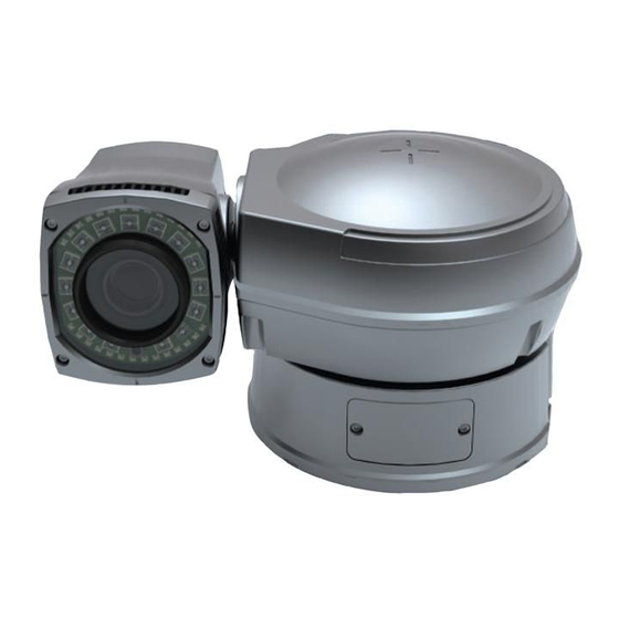
IR PTZ CAMERA
The World s First 360 Endless PAN/ TILT Motion
Auto LED Brightness Control by Distance Range
Auto LED Pulse Control by Distance Range
PAN/ TILT Torque Compensation (Step-Out Prevention)
Contents
CONTENTS------------------------------------------------------------------------------------------------------------------------
COMPONENTS--------------------------------------------------------------------------------------------------------------------
WARNINGS & CAUTIONS--------------------------------------------------------------------------------------------------------
GENERAL FEATURES--------------------------------------------------------------------------------------------------------------
User Manual
2
2
3
6
Advertisement
Table of Contents

Related Manuals for Ganz ZC-PT336N-IR


Summary of Contents for Ganz ZC-PT336N-IR
- Page 1 WE DO FUTURE User Manual Ver. 1.2 [62] IR PTZ CAMERA The World s First 360 Endless PAN/ TILT Motion Auto LED Brightness Control by Distance Range Auto LED Pulse Control by Distance Range PAN/ TILT Torque Compensation (Step-Out Prevention) Contents CONTENTS------------------------------------------------------------------------------------------------------------------------ COMPONENTS--------------------------------------------------------------------------------------------------------------------...
-
Page 2: Table Of Contents
PART NAMES---------------------------------------------------------------------------------------------------------------------- A. Basic Parts------------------------------------------------------------------------------------------------------------------- B. Connection Method--------------------------------------------------------------------------------------------------------- INSTALLATION-------------------------------------------------------------------------------------------------------------------- A. Ceiling Mount Bracket------------------------------------------------------------------------------------------------------- B. Pole Stand------------------------------------------------------------------------------------------------------------------- C. Wall Mount Bracket--------------------------------------------------------------------------------------------------------- QUICK OPERATING KEYS--------------------------------------------------------------------------------------------------------- DIAGNOSTIC---------------------------------------------------------------------------------------------------------------------- OSD MENU SETTING------------------------------------------------------------------------------------------------------------- A. OSD Menu Table------------------------------------------------------------------------------------------------------------ B. Dome Set-------------------------------------------------------------------------------------------------------------------- C. Camera Set------------------------------------------------------------------------------------------------------------------ D. Preset Set-------------------------------------------------------------------------------------------------------------------- E. -
Page 3: General Features
This symbol is intended to alert the user to the presence of un-insulated dangerous voltage within the product s enclosure that may be of sufficient magnitude to constitute a risk of electric shock to persons. This symbol is intended to alert the user to the presence of un-insulated dangerous voltage within the product s... -
Page 4: Part Names
in), illumination level of LED is automatically readjusted to get the maximum to have enough light for clear image display and reduction of energy consumption. LED 28EA, 12 LED 15EA) PAN / TILT TORQUE COMPENSATION • Pan / Tilt Torque vibration sensor keeps the Pan / Tilt Motor securely in place during strong winds. -
Page 5: Connection Method
Part Names B. Connection Method... -
Page 6: Installation
ⓐ Explanation Color Black Video Cable ⓑ Explanation Color YELLOW AUX 1-A BROWN AUX 1-B AUX 2-A WHITE AUX 2-B WHITE VIRMILION(ORANGE) ALARM 1 (AWG#20) VILOET ALARM 2 ⓒ Explanation PINK ALARM 3 SKY BLUE ALARM 4 Color BLACK AC 24 BLUE RS-485 D+ WHITE... - Page 7 A-1. When you install IR PTZ Camera on the ceiling, make 4 holes at the edge with Ø13 in diameter and 37mm in depth. If you want to connect the cables from the inside of the ceiling, also make a ole for the cables with about Ø30~50 in diameter in the center of 4 edges. (FIG.1) A-2.
-
Page 8: Pole Stand
A-5. Install 4 pieces of Anchor bolt in the holes at the edge and tight enough with Nuts. (FIG.4) A-6. Connect the cables referring to the page 8. (FIG.5) Installation B. Pole Stand COMPONENTS 1. POLE STAND 1EA 6. SCREW M4 x 16 5EA 2. - Page 9 B-2. Pass the cables of the camera through the inside of Pole Stand and connect the Camera to the Pole Stand with pieces of M4*16 screws. (FIG.7) B-3. Connect the Safety Wire of the camera to the bracket. In order to avoid getting entangled in the camera, fasten the Safety wire to the bracket with Cable Tie.
-
Page 10: Wall Mount Bracket
B-5. Adjust the Camera and Pole Stand to M10 x 45 Bolt and Flat Washer, Spring Washer. And then tight enough with Nuts. (FIG.10) Installation C. Wall Mount Bracket COMPONENTS 1. WALL MOUNT BRACKET 1EA 4. SPRING WASHER Ø4 5EA 2. - Page 11 as height. C-2. Connect the Camera to Wall Mount Bracket with 4 pieces of M4 x 16 screws and Spring Washer. (FIG.12) Installation C-3. Connect the Safety wire of the Camera to the Bracket. In order to avoid getting entangled in the Camera, fasten the Safety wire to the bracket with Cable tie.
-
Page 12: Quick Operating Keys
C-6. Connect the cables referring to the page 8. (FIG.14) Quick Operating Keys The IR Camera supports Pelco D/P Protocols The default setting of the IR Camera is Pelco D/P(Auto Detection) with 2400bps (Baud rate). [PELCO D/P PROTOCOLS] The comprehensive feature set of the camera is available from Pelco Compatible controllers via quick operation keys as defined below. -
Page 13: Diagnostic
71 ~ 78 + PRESET Status cursor to the right 81 ~ 88 + PRESET Status cursor to the left Quick Operating Keys • 65 + Preset Preset Status is displayed, to remove this screen, Press Focus Near button. • 92 + Preset This feature freezes the current live image during tour, auto scan or pattern operation. -
Page 14: Osd Menu Setting
A. PAN Origin Test Zero point of Pan is Located during the Panning test. B. Tilt Origin Test Zero point of Tilt is Located during the Tilt Test C. TX Connection Test Wait for 60 seconds for TX Connection Test. During 60 seconds, the camera is must received a signal by any control equipment as DVR or controller. - Page 15 OSD Menu Setting To enter OSD Menu, press the button 95+Preset then OSD Main Menu is displayed.
-
Page 16: Dome Set
• Use the joystick up down to move the position and left right to make selection. B. Dome Setup To enter dome setup, use the joystick right to move when cursor on dome setup. B-1. DOME SET - CAMERA ID To set camera name, and select a title of up to 16 characters using left or right direction keys or joystick. - Page 17 he default setting is 150˚/sec. B-4. DOME SET - ZOOM SPEED Move joystick right or left direction is selectable from SLOW ~ FAST. The default setting is FAST. B-5. DOME SET - ALARM You must enable the alarms for them to operate. The default setting is disabled. This function can be recalled by pushing 97+preset button.
- Page 18 B-7-2. DOME SET - [NEXT PAGE] -SYSTEM LOCK All stored dome settings can be password protected to prevent unauthorized changes. In order to enter [PASSWORD] page, the system lock status must firstly be set as ON. The default setting is OFF.
- Page 19 B-7-4. DOME SET - [NEXT PAGE] - [OSD DISPLAY] The camera ID setting defines whether the camera OSD display is displayed or switched off. B-7-5. DOME SET - [NEXT PAGE] - [SYSTEM STATUS] This page shows the information of this camera. - Protocol and baud rate are shown due to the dip switch setting - Firmware version and upgraded date will change if upgraded.
- Page 20 Press FOCUS NEAR button when the cursor is at YES in order to clear memorized data. Then each item such as tour, preset, and sector will flicker for about 2 ~ 3 seconds. After this process, the menu is returned to the previous page. •...
-
Page 21: Camera Set
OSD Menu Setting C. Camera Set C-1. CAMERA SET - FLICKERLESS The flickerless feature has options of 50Hz and 60Hz. The default setting is OFF (NTSC : 60Hz / PAL : 50Hz). The flickerless mode only needs to be set when there is a mismatch between the power frequency and camera sync rate. -
Page 22: Preset Set
White balance functions has 4 modes and may need to be changed depending on the situation. • AWB Mode : 3,200ºK to 6,500ºK (Default) • Indoor : up to 3,200ºK • Outdoor : up to 5,800ºK C-6. CAMERA SET - BLC (Back Light Compensation) From simple ON / OFF setting to user friendly BLC status indication [BLC] status with control of controller by "FOCUS FAR KEY"("... -
Page 23: Auto Scan Set
Use the joystick or pan left / right keys to select the number. D-2. PRESET - PRESET ID To create preset titles use the joystick or pan left / light keys to navigate the menu. The ZOOM TELE button moves to the next character from left to right and ZOOM WIDE button moves to the next character from right to left. -
Page 24: Tour Set
E-4. AUTO SCAN - ENDLESS Auto Scan can be set to endless rotation by enabling the endless option. The default setting is OFF. E-5. AUTO SCAN ‒ SPEED The scan speed can be programmed from 05 /S up to 35 /S. The default setting is 10 /S. -
Page 25: Privacy Set
F-7. TOUR SET - SAVE To save the memorized data and escape this page, move the joystick right or press the pan right key when cursor is at SAVE. F-8. TOUR SET - EXIT To escape this page, move joystick to the right direction. OSD Menu Setting G. -
Page 26: Pattern Set
G-4. PRIVACY SET - SAVE. After setting the privacy masking zone, to save the data, move the joystick right or pan right key when the cursor is on SAVE. After saving the data, the cursor moves to PRIVACY NO.2 automatically to prepare for the next privacy masking zone. -
Page 27: Alarm Set
OSD Menu Setting I. Alarm Set 4 Alarm inputs are available and each alarm is activating to presets, group tours or patterns. I-1. ALARM SET - ALARM NO. Up to 4 alarms are selectable by using joystick right or pressing the pan right key when the cursor is on ALARM NO. -
Page 28: Sector Set
Use the joystick or pan keys to select any preset number, Group tour No. I-4. ALARM SET - AUX ACT You can select one of BLK (No AUX triggering) / AUX1 (triggering AUX1) / AUX2 (triggering AUX2) and default value is BLK. If ALARM triggers AUX, AUX will be off after 5 seconds. -
Page 29: Dip Switching Setting
K. Exit To escape OSD Main Menu, move joystick to the right or left direction then this camera is ready to operate. Dip Switch Setting A. ID Setting The camera has camera ID to be controlled by controller or DVR. After opening, set ID using DIP SW1. - Page 30 Dip Switch Setting...
- Page 31 Dip Switch Setting...
- Page 32 Dip Switch Setting...
- Page 33 Dip Switch Setting...
- Page 34 Dip Switch Setting...
-
Page 35: 485 Termination
Dip Switch Setting B. 485 Termenation The 8th of DIP SW2 is used for 100Ω termination. Set ON DIP SW2-1st of only the last looped camera from the controller. -
Page 36: Protocol
C. Protocal The 4th, 5th of DIP SW2 above are used for protocol setting. • Factory default : Pelco-D or Pelco-P (Auto detection) D. Baud Rate Setting DIP SW2 - 4th, 5th DIP SW2 - 4th DIP SW2 - 5th BAUD RATE Pelco-D or Pelco-P Not used... -
Page 37: Specification
Specification... -
Page 38: Dimensions
Dimensions...
Need help?
Do you have a question about the ZC-PT336N-IR and is the answer not in the manual?
Questions and answers