
Related Manuals for Advantech EKI-1526


Summary of Contents for Advantech EKI-1526
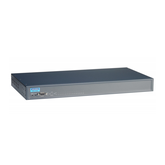
- Page 1 User Manual EKI-1526/I/TI EKI-1528/I/TI 8/16 port RS-232/422/485 Serial Device Server (Rackmount)
- Page 2 No part of this manual may be reproduced, copied, translated or transmitted in any form or by any means without the prior written permission of Advantech Co., Ltd. Information provided in this manual is intended to be accurate and reliable. How- ever, Advantech Co., Ltd.
-
Page 3: Declaration Of Conformity
This product has passed the CE test for environmental specifications when shielded cables are used for external wiring. We recommend the use of shielded cables. This kind of cable is available from Advantech. Please contact your local supplier for ordering information. -
Page 4: Document Feedback
If any item does not accord with the table, please contact your dealer immediately. One 8 or 16-port serial device server EKI-1500 driver utility and documentation CD Rack mount kits, including two L-shape metal plates and 12 screws EKI-1526(TI) | 1528(TI) User Manual... -
Page 5: Safety Instructions
SHOULD BE IN A CONTROLLED ENVIRONMENT. CAUTION: DANGER OF EXPLOSION IF BATTERY IS INCORRECTLY REPLACED. REPLACE ONLY WITH THE SAME OR EQUIVALENT TYPE RECOMMENDED BY THE MANUFACTURER, DISCARD USED BATTERIES ACCORDING TO THE MANUFACTURER'S INSTRUCTIONS. EKI-1526(TI) | 1528(TI) User Manual... - Page 6 Technical Support and Assistance Visit the Advantech web site at www.advantech.com/support where you can find the latest information about the product. Contact your distributor, sales representative, or Advantech's customer service center for technical support if you need additional assistance.
-
Page 7: About This Manual
This user manual is intended to guide professional installers in installing and config- uring the Serial Device Server. It includes technical specifications, software utility introduction, as well as procedures for the use of the software utility to self-manage the devices. EKI-1526(TI) | 1528(TI) User Manual... -
Page 8: Table Of Contents
USDG TCP Client Mode ............. 37 4.3.2 USDG Data TCP Server mode ........... 38 4.3.3 USDG UDP Server/Client mode ..........39 USDG Control mode ................39 4.4.1 Hangup Character............... 40 4.4.2 Guard Time ................. 40 RFC2217 Mode..................41 EKI-1526(TI) | 1528(TI) User Manual viii... - Page 9 Input the IP address..............74 7.2.3 Connection Success ..............74 Serial Console..................75 7.3.1 Connecting the cable ..............75 7.3.2 Select the COM port ..............75 7.3.3 COM Port Settings..............76 7.3.4 Connection Success ..............77 Command List..................77 EKI-1526(TI) | 1528(TI) User Manual...
- Page 10 7.4.12 service..................81 7.4.13 mrfc2217 ..................81 7.4.14 apply ................... 81 7.4.15 exit ....................81 7.4.16 help ..................... 81 7.4.17 reboot..................81 Chapter TCP and UDP Port Numbers.....82 List of Known TCP and UDP Port Numbers..........83 EKI-1526(TI) | 1528(TI) User Manual...
- Page 11 Rear View ........................7 Figure 2.7 System LED Panel ......................8 Figure 2.8 System LED Panel ......................8 Figure 2.9 EKI-1526/EKI-1526I Dimensions................... 9 Figure 2.10 EKI-1528/EKI-1528I Dimensions................. 10 Figure 2.11 EKI-1526T/EKI-1526TI Dimensions ................11 Figure 2.12 EKI-1528T/EKI-1528TI Dimensions ................12 Figure 2.13...
- Page 12 Figure 5.12 Accessing the Web Page through the EKI Device Configuration Utility ...... 49 Figure 6.1 Accessing the Web Page via Configuration Utility ............52 Figure 6.2 System ........................53 Figure 6.3 Ethernet Configuration ....................54 Figure 6.4 Port Configuration > Basic................... 55 Figure 6.5 Port Configuration >...
-
Page 13: Chapter 1 Overview
Chapter Overview... -
Page 14: Introduction
Ethernet network. The EKI-1526(TI) | 1528(TI) offer multiple ways to configure through Windows utility, Web Browser, serial console or Telnet console, these meth- ods make it easy manage many EKI-1526(TI) | 1528(TI) or serial devices on your network. Device Features ... -
Page 15: Device Specifications
Protection Built-in 15 KV ESD for all signals Power Power 5.6W Consumption Power Input EKI-1528(I)/EKI-1526(I): 100 ~ 240 V , 50 ~ 60 Hz EKI-1528T(I)/EKI-1526T(I): 12 ~ 48 V , Termi- nal Block EKI-1526(TI) | 1528(TI) User Manual... - Page 16 TCP/UDP client (event handling) mode Pair connection (peer to peer) mode RFC2217 mode Configuration Windows utility, Telnet console, Web Browser, serial console Management SNMP MIB-II Regulatory CE, FCC Part 15 Subpart B (Class A) Approvals EKI-1526(TI) | 1528(TI) User Manual...
-
Page 17: Chapter 2 Getting Started
Chapter Getting Started... -
Page 18: Hardware Overview
Hardware Overview 2.1.1 Front View The following view shows the EKI-1526/EKI-1526I/EKI-1526T/EKI-1526TI. EKI-1526I Link/Active Reset Serial Status Console Speed Figure 2.1 Front View No. Item Description Reset button Button allows for system soft reset (3 sec.). Serial port DB9 pinout, console port (female). -
Page 19: Figure 2.4 Rear View
Power button Turn the device off and on. Terminal block Connect cabling for power wiring. Serial port DB9 pinout, supports RS-232/422/485. ETH port RJ45 ports x 2. Ground terminal Screw terminal used to ground chassis. EKI-1526(TI) | 1528(TI) User Manual... -
Page 20: Led Indicators
2.1.3 LED Indicators The following view shows the EKI-1526/EKI-1526T/EKI-1526I/EKI-1526TI. Link/Active LAN 1 Serial Status Speed Figure 2.7 System LED Panel No. LED Name LED Color Status Description GREEN Power is on Power is off or power error condition exists Link/Active GREEN... -
Page 21: Dimensions
No. LED Name LED Color Status Description AMBER Data being transmitted No data being transmitted 2.1.4 Dimensions The following view shows the EKI-1526/EKI-1526I. 8.65 [0.34] 438 [17.24] Figure 2.9 EKI-1526/EKI-1526I Dimensions EKI-1526(TI) | 1528(TI) User Manual... -
Page 22: Figure 2.10 Eki-1528/Eki-1528I Dimensions
The following view shows the EKI-1528/EKI-1528I. 8.65 [0.34] 438 [17.24] Figure 2.10 EKI-1528/EKI-1528I Dimensions EKI-1526(TI) | 1528(TI) User Manual... -
Page 23: Figure 2.11 Eki-1526T/Eki-1526Ti Dimensions
The following view shows the EKI-1526T/EKI-1526TI. 8.65 [0.34] 438 [17.24] Figure 2.11 EKI-1526T/EKI-1526TI Dimensions EKI-1526(TI) | 1528(TI) User Manual... -
Page 24: Figure 2.12 Eki-1528T/Eki-1528Ti Dimensions
The following view shows the EKI-1528T/EKI-1528TI. 8.65 [0.34] 438 [17.24] Figure 2.12 EKI-1528T/EKI-1528TI Dimensions EKI-1526(TI) | 1528(TI) User Manual... -
Page 25: Connecting Hardware
Align the switch with the posts on the rack cabinet. Secure the switch with screws. Figure 2.14 Installing the Switch 2.2.2 Serial Connection EKI-1526(TI) | 1528(TI) Series provides 8/16 ports DB9 (male) connectors. RS-232/422/485 pin assignments as below: Figure 2.15 DB9 Pin Assignment RS-232 RS-422... -
Page 26: Power Connection
Caution! Disconnect the power cord before installation or cable wiring. The following is only available for EKI-1528/EKI-1528I/EKI-1526/EKI-1526I. Connect the EKI-1528/EKI-1528I or EKI-1526/1526I AC power line with its AC con- nector. If the power is properly supplied, you can turn on the power switch and the PWR LED will light green. -
Page 27: Chapter 3 Utility Configuration
Chapter Utility Configuration... -
Page 28: Configuration Utility Overview
Configuration Utility Overview Advantech EKI series serial device servers provide an easy-to-use utility to configure your serial device server through an Ethernet connection. For secure administration, it can also restrict the access rights for configuration to only one host PC. With this secure function enabled, other PCs will not have permission for configuration. -
Page 29: Figure 3.1 Installshield Wizard 1 Of 4
Once the InstallShield Wizard screen displays, click Next to proceed with the installation. Figure 3.1 InstallShield Wizard 1 of 4 The Software License Agreement displays, press I Agree to continue or Cancel to stop the installation. Figure 3.2 InstallShield Wizard 2 of 4 EKI-1526(TI) | 1528(TI) User Manual... -
Page 30: Figure 3.3 Installshield Wizard 3 Of 4
Figure 3.3 InstallShield Wizard 3 of 4 Once the installation of the package is finished a Configuration Utility Setup screen displays. Click Finish to conclude the process and exit the InstallShield Wizard. Figure 3.4 InstallShield Wizard 4 of 4 EKI-1526(TI) | 1528(TI) User Manual... -
Page 31: Menu Bar
Menu Bar You can open the Advantech EKI Device Configuration Utility from the Windows Start Menu by clicking Start > All Programs > EKI Device Configuration Utility > Advantech EKI Device Configuration Utility. The Configuration Utility displays as follows. For the purposes of this manual, the user interface is separated into six sections. -
Page 32: Quick Tool Bar
Quick Tool Bar The Advantech EKI Device Configuration Utility makes use of a Quick Tool Bar menu to allow quick access to the management functions. See the following figure for fur- ther information. Figure 3.6 Quick Tool Bar Overview Icon... -
Page 33: Utility Settings
NOTE: A restart is required for the settings to take effect. Click OK to save and exit the Utility Settings menu. Cancel Click Cancel to discard the changes. Apply Click Apply to save the main form settings. EKI-1526(TI) | 1528(TI) User Manual... -
Page 34: Figure 3.8 View > Settings > Device Manager
Check the check box to enable or disable answer automatically for unsigned hardware unsigned hardware installation. installation Click OK to save and exit the utility setting. Cancel Click Cancel to discard the changes. Apply Click Apply to save the utility setting. EKI-1526(TI) | 1528(TI) User Manual... -
Page 35: Discovering Your Device Server
3.4.2.1 Auto Searching Advantech EKI Serial Device Server Configuration Utility 1.67 or higher will automati- cally search all the EKI-15xx series serial device servers on the network and show them on the Serial Device Server List Area of the utility. The utility provides an auto- search function to show your device (s) by simply executing the configuration utility program from the Start Menu. -
Page 36: Figure 3.10 Selecting A Group
IP. Figure 3.10 Selecting a Group Click on the “+” before the device name, and the utility will expand the interfaces on this device server. Figure 3.11 Selecting a Device EKI-1526(TI) | 1528(TI) User Manual... -
Page 37: Network Settings
BOOTP / AutoIP: mode to automatically assign an IP address through the con- figuration server DHCP/BOOTP/AutoIP: mode to automatically assign an IP address using a Bootstrap Protocol or DHCP server. The server is set with the following default IP configuration: 10.0.0.1 (Eth1) 10.0.0.2 (Eth2) EKI-1526(TI) | 1528(TI) User Manual... -
Page 38: Figure 3.13 Network Settings Overview
“Apply” button in order to make these settings effective on the Serial Device Server. Click Reboot to reboot the serial device server. Any configuration changes you have made since the last time you saved will be lost. EKI-1526(TI) | 1528(TI) User Manual... -
Page 39: Figure 3.14 Reset Device
To reset the device: Right-click a desired device to display the settings menu. Select Reset Device. Figure 3.14 Reset Device EKI-1526(TI) | 1528(TI) User Manual... -
Page 40: Administrator Settings
Select Locate from the menu. Figure 3.15 Locate the Serial Device Server The unit’s Status LED will turn solid amber, and the buzzer will make a beep sound until you click Stop Locate. EKI-1526(TI) | 1528(TI) User Manual... -
Page 41: Securing The Serial Device Server
Right-click a desired device to display the settings menu. Select Lock Device. Figure 3.16 Lock the Serial Device Server Enter a password. Retype the password entry to confirm the profile password. Figure 3.17 Enter a Password EKI-1526(TI) | 1528(TI) User Manual... -
Page 42: Figure 3.18 Reset Device
Right-click a desired device to display the settings menu. Select Reset Device to restart the serial device server and store your setting password into the mem- ory. Figure 3.18 Reset Device EKI-1526(TI) | 1528(TI) User Manual... -
Page 43: Restore To Factory Default Settings
Power off the serial device server within ten seconds. After reconnecting the power, all settings will be reset to the factory default. If the power supply remains connected for more than ten seconds, the serial device server will not be changed. EKI-1526(TI) | 1528(TI) User Manual... -
Page 44: Resetting The Device
EKI devices. 3.5.6 Auto Mapping See “Auto Mapping” on page 43 for further details. 3.5.7 Manual Mapping See “Manual Mapping” on page 45 for further details. EKI-1526(TI) | 1528(TI) User Manual... -
Page 45: Update Firmware
3.5.8 Update Firmware Advantech continually upgrades its firmware to keep up with the ever-expanding world of computing. You can use the update firmware function in the utility to carry out the upgrade procedure. Please access Advantech’s website: http://www.advan- tech.com to download the latest version of the firmware. Before updating the firm- ware, make sure that your host’s network domain is as same as the serial device... -
Page 46: Chapter 4 Selecting An Operating Mode
Chapter Selecting An Operating Mode... -
Page 47: Overview
PC. The Advantech redirector can create up to 255 virtual COM ports. Application on the host can open virtual COM port to access the serial device servers at the same time. -
Page 48: Normal Mode
Ethernet and the outputs of serial port are mixed. When the EKI-1526(TI) | 1528(TI) Series receives data from serial port, the data will also be transmitted to the connected hosts simultaneously. -
Page 49: Usdg Data Mode
USDG Data Mode The EKI-1526(TI) | 1528(TI) Series can function either as Data server or Data client. Both operations support TCP and UDP protocols. The Series allows you to treat your serial devices as if they were networking devices. You can issue commands or trans- mit data from serial devices, connected to a EKI-1526(TI) | 1528(TI) Series device, to any devices that are connected to the Internet. -
Page 50: Usdg Data Tcp Server Mode
EKI serial device server from a single or multiple hosts. However a multi-host connection simultaneously transmits the data from a sin- gle serial port. EKI-1526I 12 13 14 15 Figure 4.5 USDG TCP Server Mode Figure 4.6 USDG Data Mode EKI-1526(TI) | 1528(TI) User Manual... -
Page 51: Usdg Udp Server/Client Mode
The default TCP/UDP port of the EKI-1526(TI) | 1528(TI) Port1 is 5300, Port2 is 5301, etc. Users can adjust them according to preference or application. Each port has its own data listen port to accept the connection requests of other network device. -
Page 52: Hangup Character
Commands are executed correctly <LF><CR> CONNECT Connect to other device <LF><CR> <LF><CR> RING ddd.ddd.ddd Detect the connection request from other device, which <LF>< CR> IP address is ddd.ddd.ddd.ddd. <LF><CR> DISCONNECT Disconnect from other device <LF><CR> EKI-1526(TI) | 1528(TI) User Manual... -
Page 53: Rfc2217 Mode
RFC2217 defines general COM port control options based on the Telnet protocol. Third party drivers supporting RFC2217 are widely available on the Internet and can be used to implement virtual COM mapping to the serial port of your device. EKI-1526(TI) | 1528(TI) User Manual... -
Page 54: Setting Up Virtual Com Redirector
Chapter Setting Up Virtual COM Redirector... -
Page 55: Setting Com Redirector
Setting COM Redirector Advantech COM port mapping software is a serial COM port redirector that creates virtual COM ports and provides access to serial devices connected to an Advantech serial device servers. Your serial device applications can communicate with serial devices connected to the Advantech serial device servers without software changes. -
Page 56: Figure 5.2 Selecting Auto Mapping
Once the mapping function is initialized, a successful mapping process results in the virtual mapping of the designated physical serial port and VCOM PC port. See the following figure. Figure 5.4 Viewing VCOM Mapping Results EKI-1526(TI) | 1528(TI) User Manual... -
Page 57: Manual Mapping
Manual Mapping On your desktop, navigate to Start > All Programs > EKI Device Configura- tion Utility and click Advantech EKI Device Configuration Utility to open the utility. Under Serial Device Servers, locate your server and click the icon to expand the listing. -
Page 58: Configuration Wizard
Configuration Wizard On your desktop, navigate to Start > All Programs > EKI Device Configura- tion Utility and click Advantech EKI Device Configuration Utility to open the utility. Under Serial Device Servers, locate your server and click the icon to expand the listing. -
Page 59: Confirming Virtual Com Settings
Confirming Virtual COM Settings On your desktop, navigate to Start > All Programs > EKI Device Configura- tion Utility and click Advantech EKI Device Configuration Utility to open the utility. Locate Serial Ports menu in the menu pane and click on the Expand icon next to Virtual COM Ports to view a list of the mapped ports. -
Page 60: Figure 5.10 System Port Vcom Mapping Configuration
Figure 5.11 Verifying VCOM Mapping Configuration If the settings do not correspond, the VCOM mapping is not correct. See “Virtual COM Port Mapping” on page 43 to re-map the VCOM ports. EKI-1526(TI) | 1528(TI) User Manual... -
Page 61: Removing Vcom Ports
Removing VCOM Ports On your desktop, navigate to Start > All Programs > EKI Device Configura- tion Utility and click Advantech EKI Device Configuration Utility to open the utility. Under Serial Ports, click the expand icon on Virtual COM Ports to view the con- figured port list. -
Page 62: Importing Vcom Mapping
To import VCOM mapping: On your desktop, navigate to Start > All Programs > EKI Device Configura- tion Utility and click Advantech EKI Device Configuration Utility to open the utility. Under Serial Device Servers, locate your server and click the icon to expand the listing. -
Page 63: Web Configuration
Chapter Web Configuration... -
Page 64: Overview
Overview EKI-1526(TI) | 1528(TI) serial device servers can be configured through a web inter- face. By using a standard web browser, the same procedure as with the Windows configuration utility can be used. In the browser’s address field, enter the IP Address of your EKI-1526(TI) | 1528(TI) serial device server.s The default IP setting is... -
Page 65: Accessing The Web Page Via Web Browser
Click Enabled or Disabled to set remote access through the Telnet Service function. VCOM Ignore Device SNMP Click Enabled or Disabled to define the SNMP daemon. Local Time Click Modify to set local date and time of the system. EKI-1526(TI) | 1528(TI) User Manual... -
Page 66: Ethernet Configuration
10.0.0.1 (Eth1) & (0.0.0.2 (Eth2). Subnet Mask Enter a value to specify the IP subnet mask for the interface. The default is 255.0.0.0. Default Gateway Enter a value to specify the default gateway for the interface. EKI-1526(TI) | 1528(TI) User Manual... -
Page 67: Port Configuration
Parity Click the drop-down menu to select the parity: None, Odd, Even, Mark or Space. Data Bits Click the drop-down menu to select the data bits: 5, 6, 7, or 8. EKI-1526(TI) | 1528(TI) User Manual... -
Page 68: Operation
Host Idle Timeout (s) Enter a value to define the host idle timeout period. Response Timeout Enter a value to define the response timeout period. (ms) Frame Break (ms) Enter a value to specify the frame break time. EKI-1526(TI) | 1528(TI) User Manual... - Page 69 “Guard Time” to define the idle time. Guard Time (ms) Enter a value to identify the guard time. RFC2217 Mode Listen Port Enter a value to identify the channel for remote initiating connections. EKI-1526(TI) | 1528(TI) User Manual...
-
Page 70: Advanced
Click the option to disable the serial port character timeout detection. Timeout Detection Disable Multiple Con- Click the option to disable the multi-access function. Then only one nection TCP connection is allowed on this serial port. EKI-1526(TI) | 1528(TI) User Manual... -
Page 71: Monitor
The Monitor function provides a method to monitor the serial device server’s status (operation mode, baud rate, data bits, stop bits, parity and RTS/XON/DTR). Monitoring information is divided into three main message types: Setting/Statistic/ Connected IP. EKI-1526(TI) | 1528(TI) User Manual... -
Page 72: Setting
Display the current RTS/CTS status of the selected port. XON/XOFF Display the current XON/OFF status of the selected port. DTR/DSR Display the current DTR/DSR status of the selected port. Save Click Save to save the values and update the screen. EKI-1526(TI) | 1528(TI) User Manual... -
Page 73: Statistic
Display the current DTR status of the selected port. Display the current DSR status of the selected port. Display the current DCD status of the selected port. Save Click Save to save the values and update the screen. EKI-1526(TI) | 1528(TI) User Manual... -
Page 74: Connected Ip
The displayed attributes are not configurable in this menu, and are for information purposes only. Item Description Connected IP Displays the IP designation for the device. IP Address Displays the current connected IP address of the selected port. EKI-1526(TI) | 1528(TI) User Manual... -
Page 75: Alert
From Email address This is the e-mail address from which automatic e-mail warnings will be sent. Email addresses 1-4 This is the e-mail address or addresses to which the automatic e-mail warnings will be sent. SNMP Trap Server EKI-1526(TI) | 1528(TI) User Manual... -
Page 76: Event
(Mail, SNMP, or log file) to record or send event messages. System event notification is available for cold start, warm start, authentication failure, IP address/Password change, serial DCD/DSR port change and Ethernet link down information. EKI-1526(TI) | 1528(TI) User Manual... -
Page 77: Figure 6.11 Alarm > Event
Figure 6.11 Alarm > Event The following table describes the items in the previous figure. Item Description System Event Cold Start Click the option to select a warning type when the device server’s power is cut off and reconnected. EKI-1526(TI) | 1528(TI) User Manual... -
Page 78: Syslogd
Figure 6.12 Syslogd > Syslogd Setting The following table describes the items in the previous figure. Item Description Syslogd Click Enabled or Disabled to set the logging service status. Save Click Save to save the values and update the screen. EKI-1526(TI) | 1528(TI) User Manual... -
Page 79: Syslogd Message
6.8.2 Syslogd Message After enabling the syslogd function, users can check the history in the syslogd mes- sage page. To access this page, click Syslogd > Syslogd Message. Figure 6.13 Syslogd > Syslogd Message EKI-1526(TI) | 1528(TI) User Manual... -
Page 80: Tools
The value ranges from 1 to 5. The count entered is not retained across a power cycle. Run ping Display the ping reply format. Save Click Save to save the values and update the screen. EKI-1526(TI) | 1528(TI) User Manual... -
Page 81: Reboot
Click Save to save the values and update the screen. 6.10.2 Change Password The Change Password function allows you to easily update your current password from a single menu. To access this page, click Management > Change Password. Figure 6.16 Management > Change Password EKI-1526(TI) | 1528(TI) User Manual... -
Page 82: Secure Access Ip
Click Save to save the values and update the screen. 6.10.4 Export Device Settings Export the server configuration settings to a .conf file. To access this page, click Management > Export. Click Export to export the serial device server settings. EKI-1526(TI) | 1528(TI) User Manual... -
Page 83: Import Device Settings
To access this page, click Management > Import. Figure 6.18 System The following table describes the items in the previous figure. Item Description Choose File Click Choose File to select the configuration file. Submit Click Submit to backup the settings. EKI-1526(TI) | 1528(TI) User Manual... -
Page 84: Telnet
Chapter Telnet... -
Page 85: Overview
Telnet Console 7.2.1 Create a new connection You can create a new Telnet connection and assign a connection name for the con- sole configuration. Figure 7.1 Creating a Telnet Connection EKI-1526(TI) | 1528(TI) User Manual... -
Page 86: Input The Ip Address
Input the IP address Confirm that the Telnet console configuration works ok. Be sure that your host PC Ethernet network IP domain is as same as the EKI-1526(TI) | 1528(TI) device server, and the Telnet TCP port number is “23”. -
Page 87: Serial Console
7.3.1 Connecting the cable You can connect to the EKI-1526(TI) | 1528(TI) serial device server’s console port with a RS-232 DB9 M-type communication cable, with the other end connecting to the host’s serial port. Make sure the connection is OK and then run the Hyper Termi- nal Program on your host. -
Page 88: Com Port Settings
7.3.3 COM Port Settings To connect the EKI-1526(TI) | 1528(TI) device server for console configuration, the port setting should match the EKI-1526(TI) | 1528(TI) device sever default settings. Figure 7.6 COM Port Settings Console configuration default Settings: Baud rate: 38400 ... -
Page 89: Connection Success
Write settings and reboot the system immediately. 7.4.1 system Usage: system Show current device status and informations. Usage: system name [Maximum length 31 bytes] Set current device name. Usage: system desc [Maximum length 127 bytes] Set current device description. EKI-1526(TI) | 1528(TI) User Manual... -
Page 90: Port
Set port Writed size of FIFO, null for disable. Usage: portadv [nn|all] rts [] Set port RTS status. – value 0 :None Setting. – value 1 :Setting power on. – value 2 :Setting accept on. – value 4 :Setting transmission on. EKI-1526(TI) | 1528(TI) User Manual... -
Page 91: Mvcom
Usage: mdata [nn|all] respto [] framebk [] Set response timeout(ms) and frame break(ms). Usage: mdata [nn|all] bysize [] bytime [] bychar [NULL|] bychartimeout [ON|OFF] Set datapackage as size(bytes) or time(ms) or character(HEX) and character- timeout. – value 0 : None Setting. EKI-1526(TI) | 1528(TI) User Manual... -
Page 92: Net
Usage: alarm event mail [cstart] [wstart] [auth] [ip] [passwd] [eth1] [eth2] Set current mail event configuration. Usage: alarm event trap [cstart] [wstart] [auth] [eth1] [eth2] Set current trap event configuration. Usage: alarm port [1|2|..] dcd [none|mail|trap|all] dsr [none|mail|trap|all] Set current port alarm configuration. EKI-1526(TI) | 1528(TI) User Manual... -
Page 93: Monitor
Save the settings to flash and reboot right now. 7.4.15 exit Usage: exit Terminate shell session 7.4.16 help Usage: help [cmd] Display help information of command cmd 7.4.17 reboot Usage: reboot Write settings and reboot the system immediately. EKI-1526(TI) | 1528(TI) User Manual... -
Page 94: Chapter 8 Tcp And Udp Port Numbers
Chapter TCP and UDP Port Numbers... -
Page 95: List Of Known Tcp And Udp Port Numbers
(TCP) Telnet (TCP) SMTP (Mail Client) (TCP/UDP) (UDP) BOOTP Server/DHCP (UDP) BOOTP Client/DHCP (TCP) Web Interface/HTTP (TCP) (TCP) SNMP (TCP/UDP) SNMP Trap (TCP) HTTPS (TCP) Modbus/TCP (Default) (TCP) Syslog (TCP/UDP) DHCPv6 Client (TCP/UDP) DHCPv6 Server EKI-1526(TI) | 1528(TI) User Manual... - Page 96 No part of this publication may be reproduced in any form or by any means, electronic, photocopying, recording or otherwise, without prior written permis- sion of the publisher. All brand and product names are trademarks or registered trademarks of their respective companies. © Advantech Co., Ltd. 2016...
Need help?
Do you have a question about the EKI-1526 and is the answer not in the manual?
Questions and answers