Table of Contents
Advertisement
Quick Links
Advertisement
Table of Contents

Related Manuals for Advantech EKI-1511L


Summary of Contents for Advantech EKI-1511L
- Page 1 User Manual EKI-1511L 1-Port RS-232 Serial Device Server...
- Page 2 No part of this manual may be reproduced, copied, translated or transmitted in any form or by any means without the prior written permission of Advantech Co., Ltd. Information provided in this manual is intended to be accurate and reliable.
- Page 3 Technical Support and Assistance Visit the Advantech web site at www.advantech.com/support where you can find the latest information about the product. Contact your distributor, sales representative, or Advantech's customer service center for technical support if you need additional assistance.
- Page 4 Before setting up the system, check that the items listed below are included and in good condition. If any item does not accord with the table, please contact your dealer immediately. 1 x Serial Device Server 1 x DIN-Rail Mounting Bracket and Screws EKI-1511L User Manual...
- Page 5 The sound pressure level at the operator's position according to IEC 704-1:1982 is no more than 70 dB (A). DISCLAIMER: This set of instructions is given according to IEC 704-1. Advantech disclaims all responsibility for the accuracy of any statements contained herein. EKI-1511L User Manual...
- Page 6 Always disconnect the power from the device before servicing it. Before plugging a cable into any port, discharge the voltage stored on the cable by touching the electrical contacts to the ground surface. EKI-1511L User Manual...
-
Page 7: Table Of Contents
USDG TCP Client Mode ............. 34 4.3.2 USDG Data TCP Server mode ........... 35 4.3.3 USDG UDP Server/Client mode ..........35 USDG Control Mode ................37 4.4.1 Hangup Character............... 37 4.4.2 Guard Time ................. 37 RFC2217 Mode..................38 EKI-1511L User Manual... - Page 8 Create a new connection ............67 7.2.2 Input the IP address..............68 7.2.3 Connection Success ..............68 Command List..................69 7.3.1 system ..................69 7.3.2 port....................69 7.3.3 portadv..................70 7.3.4 mvcom ..................70 7.3.5 mctrl .................... 70 7.3.6 mdata..................71 EKI-1511L User Manual viii...
- Page 9 7.3.12 service..................73 7.3.13 mrfc2217 ..................73 7.3.14 apply ................... 73 7.3.15 exit ....................73 7.3.16 help ..................... 73 7.3.17 reboot..................73 Chapter TCP and UDP Port Numbers.....74 List of Known TCP and UDP Port Numbers..........75 EKI-1511L User Manual...
- Page 10 Manual Mapping of a Virtual COM Port............... 43 Figure 5.8 Selecting the Configuration Wizard ................43 Figure 5.9 Serial Port Listing on EKI-1511L Device ..............44 Figure 5.10 System Port VCOM Mapping Configuration..............45 Figure 5.11 Verifying VCOM Mapping Configuration ..............45 Figure 5.12...
- Page 11 Management > Change Password ................64 Figure 6.18 Management > Secure access IP................64 Figure 6.19 Management > Import ....................65 Figure 7.1 Creating a Telnet Connection..................67 Figure 7.2 Creating a Telnet Connection..................68 Figure 7.3 Telnet Connection Console ..................68 EKI-1511L User Manual...
-
Page 12: Chapter 1 Introduction
Chapter Introduction... -
Page 13: Overview
Overview The EKI-1511L are designed to connect RS-232 serial devices such as PLC, meters, sensors, and bar code readers to an IP-based Ethernet LAN. They allow nearly any device with serial ports to connect and share an Ethernet network, while also providing various operations such as COM port redirection (Virtual COM port), TCP server, TCP client, and UDP mode. -
Page 14: Chapter 2 Getting Started
Chapter Getting Started... -
Page 15: Specifications
Power Input 9 ~ 36V Software Driver Support 32-bit/64-bit Windows 2000/XP/Vista/7/8/8.1/10, Windows Server 2003/2008/2012, and Linux Utility Advantech EKI Device Configuration Utility Operation Modes COM port redirection mode (Virtual COM) TCP/UDP server (polling) mode TCP/UDP client (event handling) mode ... -
Page 16: Hardware
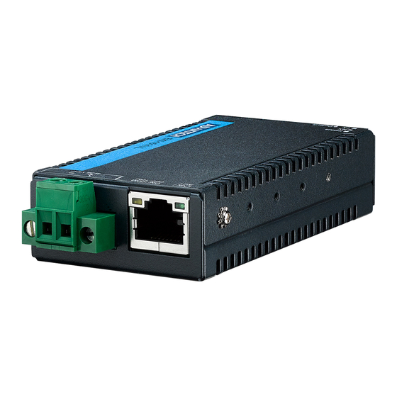
Figure 2.1 Front View No. Item Description Terminal block Connect cabling for power wiring Serial port DB9 pin-out, supports RS-232 System LED panel See “LED Indicators” on page 8 for further details. Ground terminal Screw terminal used to ground chassis EKI-1511L User Manual... -
Page 17: Rear View
Screw holes (2) used in the installation of a DIN mounting bracket or wall mounting 2.2.3 Top View Figure 2.3 Top View No. Item Description ETH port RJ45 ports x 1 Terminal block Connect cabling for power wiring EKI-1511L User Manual... -
Page 18: Bottom View
See “LED Indicators” on page 8 for further details Left View Figure 2.5 Left View No. Item Description Ground terminal Screw terminal used to ground chassis M2 screw holes Screw holes (4) for DIN brackets or wall mounting EKI-1511L User Manual... -
Page 19: Led Indicators
Data being received No data being received Tx (Serial) Green Data being transmitted No data being transmitted 2.2.6 Dimensions 46.00 [1.81] 21.20 [0.83] 23.50 [0.93] 46.00 [1.81] 13.40 [0.53] 2-M2 Draw Screw 4-M2 Draw screw Figure 2.7 Dimensions EKI-1511L User Manual... -
Page 20: Connecting Hardware
Warning! Do not install the DIN rail under or in front of the spring mechanism on the DIN rail clip to prevent damage to the DIN rail clip or the DIN rail. Make sure the DIN rail is inserted behind the spring mechanism. EKI-1511L User Manual... -
Page 21: Figure 2.9 Installing The Din-Rail Mounting Kit
See the following figure for an illustration of a completed DIN installation proce- dure. Figure 2.10 Correctly Installed DIN Rail Kit Grasp the bottom of the switch and slightly rotate it upwards. If there is resistance, the switch is correctly installed. Otherwise, re-attempt the installation process from the beginning. EKI-1511L User Manual... -
Page 22: Figure 2.11 Removing The Din-Rail
Push down on the top of the DIN rail clip release tab with your finger. As the clip releases, lift the bottom of the switch, as shown in the following illustration. Figure 2.11 Removing the DIN-Rail EKI-1511L User Manual... -
Page 23: Wall-Mounting
Use the wall mount plates as a guide to mark the locations of the screw holes. Drill four holes over the four marked locations on the wall, keeping in mind that the holes must accommodate wall sinks in addition to the screws. Insert the wall sinks into the walls. EKI-1511L User Manual... -
Page 24: Figure 2.13 Securing Wall Mounting Screws
Install the wall mount plate on the screws and slide in the direction to lock it over the keyhole, see the following figure. Figure 2.14 Wall Mount Installation Once the device is installed on the wall, tighten the screws to secure the device. EKI-1511L User Manual... -
Page 25: Serial Connection
Tighten the terminal screws to prevent the DC wires coming loose. Switch on the DC power supply. If the EKI-1511L is working properly, the blue power LED will light up, indicating that the EKI-1511L is receiving power. The EKI-1511L supports dual 9 to 36 V power inputs and power-fail relay output. -
Page 26: Chapter 3 Utility Configuration
Chapter Utility Configuration... -
Page 27: Installing The Configuration Utility
Microsoft.NET Framework version 2.0 or greater is required for this application. Insert the Advantech EKI Device Configuration Utility CD-ROM into the CD- ROM drive (whereas E:\ is the drive name of your CD-ROM) on the host PC. Use Windows explorer or the Windows Run command to execute the setup program. -
Page 28: Figure 3.2 Installshield Wizard 2 Of 4
The Software License Agreement displays, press I Agree to continue or Cancel to stop the installation. Figure 3.2 InstallShield Wizard 2 of 4 The InstallShield continues and a status screen displays. The default installation path is C:\Program Files\EKI Device Configuration Utility. Figure 3.3 InstallShield Wizard 3 of 4 EKI-1511L User Manual... -
Page 29: Figure 3.4 Installshield Wizard 4 Of 4
Once the installation of the package is finished a Configuration Utility Setup screen displays. Click Finish to conclude the process and exit the InstallShield Wizard. Figure 3.4 InstallShield Wizard 4 of 4 EKI-1511L User Manual... -
Page 30: Starting The Configuration Utility
Starting the Configuration Utility Advantech EKI-1511L device servers provide an easy-to-use utility to configure your serial device server through an Ethernet connection. For secure administration, it can also restrict the access rights for configuration to only one host PC. With this secure function enabled, other PCs will not have permission for configuration. -
Page 31: Discovering Your Device Server
Auto Searching Advantech Serial Device Server Configuration Utility will automatically search all the EKI-1511L device servers on the network and show them on the Serial Device Server List Area of the utility. The utility provides an auto-search function to show your device (s) by simply executing the configuration utility program from the Start Menu. -
Page 32: Figure 3.7 Selecting A Group
Click on the “+” before the device name, and the utility will expand the interfaces on this device server. Figure 3.8 Selecting a Device Click on each item to enter the configuration page to change the setting. The configuration will be introduced on following sections. Figure 3.9 Viewing Basic Settings EKI-1511L User Manual... -
Page 33: Network Settings
The server is set with the following default IP configuration: 10.0.0.1 (Eth1) The EKI-1511L includes a software utility option, which you can install on your system, for configuration through computer-based software. The EKI-1511L also includes a web interface option for configuration through a standard web browser. -
Page 34: Figure 3.11 Network Settings Overview
DHCP server to give IP within DHCP time out. The default value is 30 seconds. Note! When you have finished the configuration of these settings for each cat- egory, please press the “Apply” button in order to make these settings effective on the Serial Device Server. EKI-1511L User Manual... -
Page 35: Administrator Settings
From the device list frame, locate the desired device and right-click on it to dis- play the settings menu. Select Locate from the menu. Figure 3.12 Locate the Serial Device Server The unit’s Status LED lights solid blue until you click Stop Locate. EKI-1511L User Manual... -
Page 36: Securing The Serial Device Server
To lock the serial device server: Right-click a desired device to display the settings menu. Select Lock Device. Figure 3.13 Lock the Serial Device Server Enter a password. Retype the password entry to confirm the profile password. Figure 3.14 Enter a Password EKI-1511L User Manual... -
Page 37: Figure 3.15 Reset Device
Enter the password as entered in the Lock Device procedure. Figure 3.16 Unlock the Serial Device Server If you forgot the password, you must restore the setting of the serial device server to the factory defaults, which will be introduced in the next section. EKI-1511L User Manual... -
Page 38: Restore To Factory Default Settings
Power off the serial device server within ten seconds. After reconnecting the power, all settings will be reset to the factory default. If the power supply remains connected for more than ten seconds, the serial device server will not be changed. EKI-1511L User Manual... -
Page 39: Resetting The Device
Right-click a desired device to display the settings menu. Select Reset Device. Figure 3.18 Reset Device The device resets. Once the process is complete, the serial device server displays under the Serial Device Server listing once again. EKI-1511L User Manual... -
Page 40: Add To Favorite
The Add to Favorite function allows to easily map available devices to Favorite’s. By bookmarking specific devices, you can create quickly accessible shortcuts for existing critical devices from the vast pool of locally or remotely networked EKI-1511L devices. Figure 3.19 Add to Favorite 3.4.6... -
Page 41: Update Firmware
Note! Be sure that the host PC Ethernet network domain is as same as the EKI-1511L serial device server or the host PC can establish the TCP connection with the serial device server while doing the updating firm- ware process. -
Page 42: Chapter 4 Selecting An Operating Mode
Chapter Selecting An Operating Mode... -
Page 43: Overview
PC. The Advantech redirector can create up to 255 virtual COM ports. Application to the host can open a virtual COM port to access the serial device servers at the same time. -
Page 44: Normal Mode
Ethernet and the outputs of serial port are mixed. When the EKI-1511L receives data from serial port, the data will also be transmitted to the connected hosts simultaneously. -
Page 45: Usdg Data Mode
USDG Data Mode The EKI-1511L can function as either a Data TCP server or a Data TCP client. Both operations support TCP and UDP protocol. The EKI-1511L allows you to treat your serial devices as if they were networking devices. You can issue commands or transmit data from serial devices, connected to a EKI-1511L device, to any devices that are connected to the Internet. -
Page 46: Usdg Data Tcp Server Mode
4.3.2 USDG Data TCP Server mode In TCP server mode, the TCP connection is initiated from the host to the EKI-1511L device server. This operation mode supports a maximum of five simultaneous connections for each serial port on an EKI-1511L device server from a single or multiple hosts. - Page 47 The default TCP/UDP port of the EKI-1511L Port1 is 5300. Users can adjust them according to preference or application. Each port has its own data listen port to accept the connection requests of other network device.
-
Page 48: Usdg Control Mode
USDG Control Mode In controlling mode, the EKI-1511L device server presents a modem interface to the attached serial device: it accepts AT-style modem commands to connect / disconnect to other networking device. If you want a serial device running application program to connect/disconnect to different devices on request, this function is available through the USDG Control mode. -
Page 49: Rfc2217 Mode
EKI-1511L devices to a local COM port on a host computer. RFC2217 defines general COM port control options based on the Telnet protocol. Third party drivers supporting RFC2217 are widely available on the Internet and can be used to implement virtual COM mapping to the serial port of your device. -
Page 50: Setting Up Virtual Com Port
Chapter Setting up Virtual COM Port... -
Page 51: Setting Com Port Redirector
Setting COM Port Redirector Advantech COM port mapping software is a serial COM port redirector that creates virtual COM ports and provides access to serial devices connected to an Advantech serial device servers. Your serial device applications can communicate with serial devices connected to the Advantech serial device servers without software changes. -
Page 52: Figure 5.2 Selecting Auto Mapping
The selected address displays the Device Port and (EKI-1511L device server physical serial port) and the system port which will be the VCOM port for the PC. System Port Selected Options Device Port Figure 5.2 Selecting Auto Mapping From the network address list, select the address options to map. -
Page 53: Manual Mapping
Figure 5.5 Selecting Manual Mapping The Manual Mapping Virtual COM Port window displays. With the EKI-1511L, there is only a single port. It is not necessary to select from the Serial Port field. In the Host > COM Port drop-down menu, select the target COM port to map. -
Page 54: Configuration Wizard
Configuration Wizard On your desktop, navigate to Start > All Programs > EKI Device Configura- tion Utility and click Advantech EKI Device Configuration Utility to open the utility. Under Serial Device Servers, locate your server and click the icon to expand the listing. -
Page 55: Confirming Virtual Com Settings
Locate the radio button correlating to the target port to modify and click on it to select it. Verify the Device Port (EKI-1511L device physical serial port) and System Port (virtual COM port for PC) settings before continuing. Click Finish to complete the process. A Wizard complete! screen displays indicating the completion of a successful procedure. -
Page 56: Figure 5.10 System Port Vcom Mapping Configuration
The newly mapped VCOM port is listed under the same mapped settings used in the previous steps. The settings correspond to the VCOM port configuration on the EKI-1511L device, see the following figure. Figure 5.11 Verifying VCOM Mapping Configuration If the settings do not correspond, the VCOM mapping is not correct. See “Virtual COM Port Mapping”... -
Page 57: Removing Vcom Ports
Removing VCOM Ports On your desktop, navigate to Start > All Programs > EKI Device Configura- tion Utility and click Advantech EKI Device Configuration Utility to open the utility. Under Serial Ports, click the expand icon on Virtual COM Ports to view the configured port list. -
Page 58: Exporting And Importing Vcom Mapping
File menu. Running a Diagnostic Test The loopback test allows you to determine if the EKI-1511L device server is config- ured correctly to identify any failed nodes in the network. The test allows you to send a signal from the server and return (looped back) it back to the server. -
Page 59: Web Interface
Chapter Web Interface... -
Page 60: Overview
Windows configuration utility can be used. In the browser’s address field, enter the IP Address of your EKI-1511L serial device server. The default IP setting is 10.0.0.1, but you should use the IP which you have previously assigned for this device. -
Page 61: Accessing The Web Page Via Web Browser
Save Click Save to save the values and update the screen. Ethernet Configuration Choose Eth 1 in the Ethernet Configuration page. Enter the corresponding values for your network environment. Remember press Save after fill in all values. EKI-1511L User Manual... -
Page 62: Figure 6.3 Ethernet Configuration
Displays the current IP address 3 of the device. Save Click Save to save the values and update the screen. Note! All new configurations will take effect after rebooting. To reboot the device, click Tools > Reboot. EKI-1511L User Manual... -
Page 63: Port Configuration
Click the drop-down menu to select the flow control mode: None, XOn/XOff, RTS/CTS Save Click Save to save the values and update the screen. 6.5.2 Operation The Operation menu allows for the configuration of the mode type and related attributes for port configuration. EKI-1511L User Manual... -
Page 64: Figure 6.5 Port Configuration > Operation
Click the drop-down menu to select port data buffering type: None or RAM. When Data Full Click the drop-down menu to select process mode when data full: Stop. Save Click Save to save the values and update the screen. EKI-1511L User Manual... -
Page 65: Advanced
Click Save to save the values and update the screen. Monitor The EKI-1511L device server allows monitoring of the serial ports’ status. The serial port’s operation mode and status is available for display. The IP address of the host PC which is communicating with serial port is also displayed. -
Page 66: Setting
Display the current stop bits of the selected port. Parity Display the current parity of the selected port. RTS/CTS Display the current RTS/CTS status of the selected port. XON/XOFF Display the current XON/OFF status of the selected port. EKI-1511L User Manual... -
Page 67: Statistic
Display the current total Tx count of the selected port. Total Rx Count Display the current total Rx count of the selected port. Display the current RTS status of the selected port. Display the current CTS status of the selected port. EKI-1511L User Manual... -
Page 68: Connected Ip
Figure 6.9 Monitor > Connected IP The following table describes the items in the previous figure. Item Description Connected IP Displays the IP designation for the device. IP Address Displays the current connected IP address of the selected port. EKI-1511L User Manual... -
Page 69: Auto Warning (Alarm)
SNMP message. The Simple Network Management Protocol (SNMP) is used by the serial device server to collect detailed information about the serial device server. To access this page, click Alarm > Setting. Figure 6.10 Alarm > Setting EKI-1511L User Manual... - Page 70 Write Community Enter the write-only, private, community string. Contact Enter the individual designated the contact point for this event. Location Enter the designated location/department of the setting. Save Click Save to save the values and update the screen. EKI-1511L User Manual...
-
Page 71: Event
Click Save to save the values and update the screen. Syslogd The EKI-1511L device server provides the functionality to allow network devices to send event messages to a logging server, also known as a Syslog server, by way of the Syslogd function. The Syslog protocol is supported by a wide range of devices and can be used to log different types of events. -
Page 72: Syslogd Message
Click Save to save the values and update the screen. 6.8.2 Syslogd Message After enabling the syslogd function, users can check the history in the syslogd message page. To access this page, click Syslogd > Syslogd Message. Figure 6.13 Syslogd > Syslogd Message EKI-1511L User Manual... -
Page 73: Tools
Tools The EKI-1511L device server provides tools for access to ping and reset functions. 6.9.1 Ping The Ping page can help users diagnose Ethernet problems. Users can use the ping page to ask the device to ping a specific target to check the Ethernet network status. -
Page 74: Reboot
6.10 Management The EKI-1511L device server allows for easy installation and maintenance and reliable maintenance access from anywhere. With the reliable management tools available, you can streamline staffing and troubleshooting requirements to a centralized system. -
Page 75: Change Password
Click Save to save the values and update the screen. 6.10.4 Export Device Settings Export the server configuration settings to a .conf file. To access this page, click Management > Export. Click Export to export the serial device server settings. EKI-1511L User Manual... -
Page 76: Import Device Settings
To access this page, click Management > Import. Figure 6.19 Management > Import The following table describes the items in the previous figure. Item Description Choose File Click Choose File to select the configuration file. Submit Click Submit to backup the settings. EKI-1511L User Manual... -
Page 77: Telnet/Serial Console Configuration66
Chapter Telnet/Serial Console Configuration... -
Page 78: Overview
You can use terminal software like Hyper Terminal, Telix and other related terminal software. Telnet Console 7.2.1 Create a new connection You can create a new Telnet connection and assign a connection name for the con- sole configuration. Figure 7.1 Creating a Telnet Connection EKI-1511L User Manual... -
Page 79: Input The Ip Address
Input the IP address Confirm that the Telnet console configuration works. Click OK. Be sure that your host PC Ethernet network IP domain is as same as the EKI-1511L device server, and the Telnet TCP port number is “23”. Figure 7.2 Creating a Telnet Connection 7.2.3... -
Page 80: Command List
Acceptable baud: 300, 600, 1200, 1800, 2400, 4800, 7200, 9600, 14400, 19200, 38400, 57600, 115200, and 230400 – parity n: None Parity. – parity e: Even Parity. – parity o: Odd Parity. – parity m: Mark Parity. – parity s: Space Parity. EKI-1511L User Manual... -
Page 81: Portadv
Show port mode and mode informations. Usage: mctrl [nn|all] Set port [nn|all] as control mode. Usage: mctrl [nn|all] idleto [] tcpp [] atp [] guardt [] hangchr [] Set data idle timeout(s) data listen port command listen port guard time(ms) hangup character. EKI-1511L User Manual... -
Page 82: Mdata
Set network timeout. 7.3.8 password Usage: password Display two different Usage. Usage: password new [1-31 characters] Set new password. Usage: password old [**...] new [1-31 characters] Confirm the old password and set new password. 7.3.9 alarm Usage: alarm EKI-1511L User Manual... -
Page 83: Monitor
Monitor COM port statistic data. Usage: monitor port [1|2|..] ip Monitor connected IP. 7.3.11 time Usage: time Show current time informations. Usage: time [YYYYMMDDhhmmss] Set current time configuration. Usage: time ntp [timeserver] Set current time server configuration. EKI-1511L User Manual... -
Page 84: Service
Save the settings to flash and reboot right now. 7.3.15 exit Usage: exit Terminate shell session. 7.3.16 help Usage: help [cmd] Display help information of command cmd. 7.3.17 reboot Usage: reboot Write settings and reboot the system immediately. EKI-1511L User Manual... -
Page 85: Chapter 8 Tcp And Udp Port Numbers
Chapter TCP and UDP Port Numbers... -
Page 86: List Of Known Tcp And Udp Port Numbers
5202 (TDP) VCOM 9999 (TDP) Firmware Download (TDP) (TDP) Telnet (TDP) SMTP (Mail Client) (TCP/UDP) (UDP) BOOTP Server/DHCP (UDP) BOOTP Client/DHCP (TDP) Web Interface/HTTP (TDP) (TDP) SNMP (TCP/UDP) SNMP Trap (TDP) HTTPS (TDP) Modbus/TCP (Default) (TDP) Syslog EKI-1511L User Manual... - Page 87 No part of this publication may be reproduced in any form or by any means, electronic, photocopying, recording or otherwise, without prior written permission of the publisher. All brand and product names are trademarks or registered trademarks of their respective companies. © Advantech Co., Ltd. 2020...
Need help?
Do you have a question about the EKI-1511L and is the answer not in the manual?
Questions and answers