
Related Manuals for Advantech EKI-1351


Summary of Contents for Advantech EKI-1351
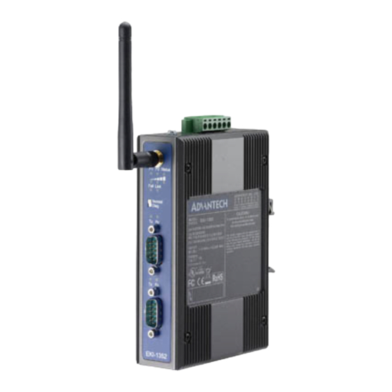
- Page 1 User Manual EKI-1351/1352 1/2-port RS-232/422/485 to 802.11b/g WLAN Serial Device Servers...
- Page 2 No part of this manual may be reproduced, copied, translated or transmitted in any form or by any means without the prior written permission of Advantech Co., Ltd. Information provided in this manual is intended to be accurate and reliable. How- ever, Advantech Co., Ltd.
-
Page 3: Declaration Of Conformity
Consult the dealer or an experienced radio/TV technician for help. Technical Support and Assistance Visit the Advantech web site at www.advantech.com/support where you can find the latest information about the product. Contact your distributor, sales representative, or Advantech's customer service center for technical support if you need additional assistance. - Page 4 The sound pressure level at the operator's position according to IEC 704-1:1982 is no more than 70 dB (A). DISCLAIMER: This set of instructions is given according to IEC 704-1. Advantech disclaims all responsibility for the accuracy of any statements contained herein.
-
Page 5: Table Of Contents
Contents Chapter Overview..........1 Introduction ....................2 Features ....................3 Specifications .................... 3 Package Check List .................. 4 Chapter Getting Started........5 Understanding EKI-1351/1352..............6 2.1.1 Product Description............... 6 Figure 2.1 Wireless LAN Connections......... 6 2.1.2 COM Port Redirector (Virtual COM Port)........7 Figure 2.2 COM Port Redirector .......... - Page 6 Network Settings..................27 3.3.1 Wireless Basics ................29 3.3.2 Wireless Authentication .............. 32 3.3.3 Wireless Advanced ..............34 Serial Settings..................35 3.4.1 Setting Serial Port Parameters ........... 36 3.4.2 Setting Virtual COM Operating Mode Parameters...... 37 3.4.3 Setting TCP/UDP Server/Client Operating Mode Parameters..39 3.4.4 Setting Control Operating Mode Parameters......
-
Page 7: Chapter 1 Overview
Chapter Overview... -
Page 8: Introduction
Introduction Advantech's EKI-1300 series of Industrial Device Servers are a robust, feature-rich, and cost effective way to network-enable equipment in an industrial automation envi- ronment. The EKI-1351/1352 provides one or two serial ports, 802.11b/g wireless LAN interface to connect any RS-232/422/485 devices to wireless LAN. These wire-... -
Page 9: Features
Features Expand up 255 serial ports for one Windows 2000/XP/Vista (x86) host Link any serial device to an IEEE 802.11 b/g network Supports wireless LAN Ad-Hoc and Infrastructure modes Supports high transmission speed up to 921.6 kbps Supports various operation mode: COM port redirection (Virtual COM), TCP server/client, UDP mode, and Pair Connection Supports LED indicators: easy to diagnose Supports integrated Configuration Utility and Port-Mapping Utility: easy to config-... -
Page 10: Package Check List
Software Utility: Advantech Serial Device Server Configuration Utility Driver support: Windows 2000/XP/Vista(x86) Operation Mode: – COM port redirection (Virtual COM) – TCP/UDP server (polling) mode – TCP/UDP client (event handling) mode – Pair connection mode Configuration: Web interface, Windows utility... -
Page 11: Chapter 2 Getting Started
Chapter Getting Started... -
Page 12: Understanding Eki-1351/1352
Understanding EKI-1351/1352 The EKI-1351/1352 is network-based, serial device server for connecting RS-232/422/485 devices, such as CNCs, PLCs, scales, and scanners, directly to a TCP/IP network. Once connected through EKI-1351/1352, serial device will be able to send and receive data on a network like any other network device. It extends tradi- tional COM ports of a PC with access over a TCP/IP network. -
Page 13: Com Port Redirector (Virtual Com Port)
PC. The Advantech redirector can create up to 255 virtual COM ports. Application on the host can open virtual COM port to access the serial device servers at the same time. -
Page 14: Figure 2.3 Multi-Access Mode
2.1.2.2 Multi-Access Mode (Shared COM port mode) Most of serial devices are connected directly and physically to the PC serial ports via a cable. The operation system, ex. Windows XP, provides the COM ports that user’s application can access, and control the serial device through the serial cable. This means that the serial device can be connected to one host and only one application on this host can handle input, output and control operation on this device. -
Page 15: Tcp Server Mode
IP address and TCP port number of the network hosts which the EKI serial device server connect to using Advantech Serial Device Server Configuration Utility. After configuration, when EKI serial device server receives the data from serial port, the device server will employ the connection to hosts which are configured. -
Page 16: Serial Tunneling Mode
Two native serial devices can communicate over an Ethernet network without any intermediate host PC and software programming. Serial Tunneling is very simple to use. You can use Advantech Serial Device Server Configuration Utility to designate one serial port as the tunneling master and another serial device server port as the tunneling slave. -
Page 17: Hardware
Hardware In this section, we will give you an overview of EKI-1351/1352 hardware and installation. 2.2.1 LED Indicators There are LEDs display the power status, network status, and serial communication status located on the front panel of EKI-1351 and EKI-1352, each of them has its own specific meaning as below. -
Page 18: Dimensions (Units: Mm)
2.2.2 Dimensions (Units: mm) 2.2.2.1 EKI-1351 and EKI-1352 Figure 2.7 Front View of EKI-1351/1352 Figure 2.8 Side View of EKI-1351/1352 EKI-1351/1352 User Manual... -
Page 19: Figure 2.9 Back View Of Eki-1351/1352
Figure 2.9 Back View of EKI-1351/1352 Figure 2.10 Top View of EKI-1351/1352 EKI-1351/1352 User Manual... -
Page 20: Connecting Hardware
Connecting Hardware Next, we will explain how to find a proper location for your EKI-1351/1352, and then explain how to connect to the network, hook up the power cable, and connect to the EKI-1351/1352 serial port. 2.3.1 Choosing the Location Due to its versatility and innovative design, EKI serial device server can be: Fixed to a panel mount Fixed to a DIN-rail. -
Page 21: Din-Rail Mounting
2.3.3 DIN-rail Mounting You can mount the EKI-1351/1352 on a standard DIN rail. The DIN-rail kit is screwed on the serial device server when out of factory. If the DIN-rail kit is not screwed on the serial device server, please screw the DIN-rail kit on the serial device server first. First, hang the EKI-1351/1352 to the DIN-rail with angle of inclination. -
Page 22: Switch Settings
2.3.4 Switch Settings Normal Mode (Normal) In normal use, you should move the switch to Normal Mode (Normal), and use the configuration utility to configure EKI-1351/1352 for different BSS --- Infrastructure mode or Ad hoc mode. Diagnostic Mode (Diag.) If your network connection is broken or you forgot your WLAN serial device server settings, or you forgot the WEP key, you can move the switch to Diagnostic Mode (Diag) to rebuild the settings and connection. -
Page 23: Wireless Connection
Note! Please refer to Appendix A “Quick Start” if setting or resetting the wireless connection 2.3.5 Wireless Connection EKI-1351 and EKI-1352 operate in the 802.11b/g WLAN environment, which is created by an access point working with 802.11b/g protocols. Locate your access point and connect to the Ethernet network first. -
Page 24: Serial Connection
Note! Be sure Microsoft .NET Framework on host PC is greater than version 2.0. Insert the Advantech IEDG SERIES DRIVER UTILITY CD-ROM into the CD- ROM drive (e.g. D:\) on the host PC. Use Windows Explorer or the Windows Run command to execute the Configuration Utility setup program. - Page 25 Carefully read the Software License Agreement, and press “Yes” to continue the process. The setup program will specify a default installation path: C:\Program Files\Advantech eAutomation\Serial Device Server Configuration Utility\, press “Install” button to continue the process. EKI-1351/1352 User Manual...
- Page 26 After setup program has copied all program files to your computer, press “Finish” button for completing the installation process. EKI-1351/1352 User Manual...
-
Page 27: Chapter 3 Configuration
Chapter Configuration... -
Page 28: Configuration Utility Overview
Advantech Serial Device Server Configuration Utility is an excellent device server management tool. You can connect and configure the local and remote Advantech serial device servers easily. Moreover, Virtual COM port will be enabled in the same utility. Using this utility, you can:... -
Page 29: Discovering Serial Device Servers
Device Server List Area of the utility. The utility provides an auto-search function to show your device(s) by simply executing the configuration utility program from the Start Menu as follows: Start Menu --> All Program --> Advantech eAutomation --> Serial Device Server Configuration Utility From here all device on the same network domain will be searched and display on Device Server List Area. - Page 30 Click on the “+” before the device name, and the utility will expand the interfaces on this device server. Click on each item, you will entry the configuration page to change the setting. The configuration will be introduced on following sections. EKI-1351/1352 User Manual...
- Page 31 EKI-1351/1352 User Manual...
-
Page 32: Clear Device List And Search Again
3.2.2 Clear Device List and Search Again You can click the button on the “Quick Tool Area”; utility will clear all list device servers in the Device Server List Area and re-search again. Don’t use this function frequently. The warning message will be pop-up when you double click this button. -
Page 33: Network Settings
Network Settings This section explains how to configure the EKI-1351/1352 series network using this utility so that it can communicate over a network with serial devices. Click on the “+” before the model name (e.g. EKI-1352), and the utility will expand the tree structure to show the individual device name. - Page 34 IP address, Subnet Mask, Default Gateway: You can choose from four possible IP Configuration modes --- Static or DHCP. Static IP User defined IP address, Subnet Mask, and Default Gateway. DHCP + Auto-IP DHCP Server assigned IP address, Subnet Mask, Default Gateway, and DNS. Note! When you have finished the configuration of these settings for each cat- egory, please press the “Apply”...
-
Page 35: Wireless Basics
3.3.1 Wireless Basics 3.3.1.1 Wireless Basic Information Firmware Version: Here is the firmware version of the wireless module embed- ded in the EKI-1531 and EKI-1352. The wireless module firmware might affect the wireless connection. Write down the version number and provide to our cus- tomer service if you have wireless connection problems. - Page 36 3.3.1.3 Wireless Basic Settings Region: Set the region. Each region has its default channel range. When you choose a specific region, the optional channel range and numbers in the below drop-down menu will be changed automatically. Mode: There are two kinds of basic service set (BSS) in this drop-down menu. 802.11b/g Infrastructure mode : For infrastructure BSS usage, you should set up the SSID of the specific access point (AP).
- Page 37 Data Rate: The data transmission rate is determined by the device and access point. If there is a restriction for the device or AP, a fixed data rate has to be cho- sen. Otherwise, we suggest the “Automatic” choice. SSID: You can input the AP SSID here. If you doesn’t know which access point is the most appropriate one, just set ”ANY”...
-
Page 38: Wireless Authentication
3.3.2 Wireless Authentication EKI-1351 and EKI-1352 now support WEP (Wired Equivalent Privacy) encryption operation mode. WEP is a kind of standard to encrypt the data frame. We will enhance other encryption mode in future. Authentication Type: There are three kinds of types in this drop-down menu. Open System: No encryption for network communication. - Page 39 Alphanumeric Hexadecimal 64 bits Up to 5 random characters Up to 10 random hexadecimal on the keyboard characters (0 ~ 9, a ~ f) 128bits Up to 13 random characters Up to 26 random hexadecimal on the keyboard characters (0 ~ 9, a ~ f) Key Index: This lists the supported encryption keys that you can choose from Key Value: You can set up the key value in this index.
-
Page 40: Wireless Advanced
3.3.3 Wireless Advanced The tab identifies several parameters that are related to the 802.11b/g wireless net- work. We strongly suggested the default settings are not changed unless necessary. If you want to recovery to factory value, you click the “Reset to factory default value”. Parameters Default Value Range... -
Page 41: Serial Settings
3.3.3.2 RTS Threshold RTS Threshold is the frame size above that an RTS/CTS handshake will be per- formed before attempting to transmit. RTS/CTS ask for permission to transmit to reduce collisions, but add considerable overhead. Disabling RTS/CTS can reduce overhead and latency in WLANs where all stations are close together, but can increase collisions and degrade performance in WLANs where stations are far apart and unable to sense each other to avoid collisions. -
Page 42: Setting Serial Port Parameters
3.4.1 Setting Serial Port Parameters Description: You can give a more detailed description on the function of the port for easier management and maintenance. Descriptions have a limit of 128 char- acters. Type: The EKI-1351/1352 offers three kinds of serial protocols, RS-232, RS-422 and RS-485. -
Page 43: Setting Virtual Com Operating Mode Parameters
3.4.2 Setting Virtual COM Operating Mode Parameters The Advantech serial device servers extend traditional COM ports of a PC to Ether- net access. Through Ethernet networking, users can control and monitor remote serial devices and equipment over LAN or WAN. Advantech serial device servers come with a COM port redirector (Virtual COM driver) that transmits all serial signals intact. - Page 44 Host Idle Timeout (10~255 seconds): The "Host Idle Timeout" setting monitors the connection between the host and the device. If the "Host Idle Timeout" set- ting time is reached, the device server will release the resources allocated to the port mapping. This prevents a stalled host from affecting the connectived device.
-
Page 45: Setting Tcp/Udp Server/Client Operating Mode Parameters
Round-Robin mode: Enabling “Response Timeout” parameter, the EKI-1351/ 1352 will operate in “Round-Robin mode”. Each serial port supports up to five simultaneous connections, so multiple hosts can transmit/receive data to/from the same serial port simultaneously. Every host can transmit data to the same serial port simultaneously, but EKI serial device server will process the data communication in order. - Page 46 Mode: There are two kinds of operation modes: Data Mode and Control Mode. To use TCP server operating mode correctly, you have to select Data Mode. Data Listen Port: The TCP (UDP) port number represents the source port num- ber, and the number is used to identify the channel for remote initiating connec- tions.
-
Page 47: Setting Control Operating Mode Parameters
Protocol: TCP and UDP. Enable Time sharing: This function is the same with the Multi-Access function. Please refer to the virtual COM operating mode setting. Peers to Receiving Data: You can set maximum 4 network devices which you want to connect. You need to fill out the IP Address and Port of network devices which you want to connect. -
Page 48: Table 3.1: At Commands List
Please refer to the TCP/UDP server operating mode to setup the Data Listen Port, Command Listen Port, and Data Idle Timeout. Hangup Character: The default character is “+”. After you have connected to another serial device via EKI-1351/1352, you may need to disconnect. Then you can use the command "+++"... -
Page 49: Advanced Setting
3.4.5 Advanced Setting The EKI-1351/1352 serial device server provides the advanced settings for some special applications which need critical time requirements. In normal applications, these settings are recommended not to be set to avoid the unusual action happened. Delay Time (ms) When you enable the delay time, the serial port will postpone the received data for the time interval you set, and then send the received data to the TCP/IP network. -
Page 50: Security Configuration
Security Configuration 3.5.1 Accessible Function Allow any IP to access. If this function is enabled, any PC can access data from this serial device server. Specified IP which can access If you want to restrict access to certain PCs, you can list their IP addresses in this area. -
Page 51: Port Monitor
3.5.2 Port Monitor Advantech Serial Device Server Configuration Utility provides an excellent function to monitor the serial port status. Users can check the status of the serial ports. Refresh Update port status manually when you click “Refresh” button. Auto Refresh You can set up the scanning period you want to auto refresh the port status. -
Page 52: Import/Export Serial Port Setting
3.6.1 Import/Export Serial Port Setting You can save or recover the configuration of serial port via .sps file format. 3.6.2 Locate Serial Device Once you use this function, the device sever you chose to locate, its “Status” LED will be lit until you click “Stop Locate” option. EKI-1351/1352 User Manual... -
Page 53: Lock Device
3.6.3 Lock Device The configuration utility provides Lock Device function (password protection), when you use this function you need to fill in a set of password. Then, other host computers will no longer to configure this device server. Notice that you need to "Reset Device" in order to store password into the device server. -
Page 54: Upgrading The Firmware
3.6.5 Upgrading the Firmware Advantech continually upgrades its firmware to keep up with the ever-expanding world of computing. You can use the update firmware function in the utility to carry out the updating procedure. Please access Advantech’s Website at http:// www.advantech.com to download the latest version of the firmware. - Page 55 Select the firmware you want to update. After downloading the firmware completely, click on the “OK” button. The serial device server will restart automatically. EKI-1351/1352 User Manual...
- Page 56 EKI-1351/1352 User Manual...
-
Page 57: Setting Com Redirector
Chapter Setting COM Redirector... -
Page 58: Setting Com Redirector(Virtual Com Port)
Setting COM Redirector(Virtual COM port) Advantech COM port mapping software is a serial COM port redirector that creates virtual COM ports and provides access to serial devices connected to Advantech serial device servers. Your serial device applications can communicate with serial devices connected to Advantech serial device servers without software changes. - Page 59 The COM ports in the “Virtual Com Ports” list are now available for use by Windows applications. EKI-1351/1352 User Manual...
-
Page 60: Manual Mapping
4.1.2 Manual Mapping Right click the serial device name on the sub-tree of Device Server List area and select the “Manual Mapping” function. ADAM series, EDG series, and EKI wireless series have only one IP address. You can select the serial port on the device server and the host COM that you want to set. Press <Map it>... - Page 61 Advantech serial device server. The function "Auto Reconnect" is for this purpose, if the Advantech serial server loses the connection to its host, the COM redirector will try to re-establish the connection while the host’s AP access the virtual COM port.
-
Page 62: Manual Direct Mapping Virtual Com Port
4.1.3 Manual Direct Mapping Virtual COM Port Click the button on the Quick Took area, you can add a target by selecting the Device Type and inputting the IP address without physically connecting the serial device server to the network. 4.1.4 Remove the Virtual COM Port If you want to remove the virtual COM port, you can remove them one by one or... -
Page 63: Running Diagnostic Test
Running Diagnostic Test The purpose of this test is to make sure the communication from host PC to EKI- 1351/1352 is OK. If there is still an error, you can check the communication from the EKI-1351/1352 to the devices. If the test is selected, an external test will be done to check that the connection signals for each port are working properly. - Page 64 Select which COM port you want to run diagnostic test, and then press “Test” button to process the testing. Signal Test RTS -> CTS check the RTS and CTS signal between two ports DTR -> RI check the DTR and RI signal between two ports DTR ->...
-
Page 65: Web-Based Configuration
Chapter Web-Based Configuration... -
Page 66: Overview
Overview EKI-1351/1352 serial device server can be configured through a web interface. By using a standard web browser, the same procedure as with the Windows configura- tion utility can be used. In the browser’s address field, enter the IP Address of your EKI-1351/1352 serial device server. - Page 67 By Internet Browser EKI-1351/1352 User Manual...
-
Page 68: System
System You can change the Device Name and Device Description on this page. Network Configuration Click the Net Configuration, there are Net Mode, IP Address, Subnet Mask, and Default Gateway. Enter the corresponding values for your network environment. Remember press “Save” after fill in all values. EKI-1351/1352 User Manual... -
Page 69: Port Configuration
Note! All new configurations will take effect after rebooting. The reboot func- tion is located on the main menu of the Web Configuration. Port Configuration There are Basic, Operation Mode, and Advanced Setting in the serial port configuration. For more detailed information for setting, please refer to chapter 3.4 and chapter 3.5. -
Page 70: Change Password
Change Password You can change the serial device server password on here: If you have set a password via the configuration utility or Telnet or serial console, when you access the web configuration, you need to key in the password. Do not need to enter the username in the dialog. -
Page 71: Reboot
Reboot The configuration will take effect after clicking “Save” button. But all configurations will save to flash memory after this reboot step. Press the “Reboot” button and the system will give a reset response. It will take a few seconds to reconnect with the new values. - Page 72 EKI-1351/1352 User Manual...
-
Page 73: Appendix A Quick Start
Appendix Quick Start... -
Page 74: Diagnostic Ad Hoc Mode
There are two ways to complete the wireless connection between an access point and EKI-1351/1352; via Diagnostic Ad hoc Mode or Diagnostic Infrastructure Mode. We recommend you use Ad hoc if your host PC is equipped with a wireless module. Diagnostic Ad hoc Mode (With wireless module) Set the switch of EKI-1351/1352 to Diagnostic Mode, then power on. -
Page 75: Diagnostic Infrastructure Mode
Reset the Ethernet Basic settings and Wireless Basic settings as needed. (About these settings, please refer to section 3.3.1 and 3.3.2 of the manual) Power off EKI-1351/1352, adjust the switch to Normal Mode, and then reboot it to finish the wireless connection. Now you can configure and set up port mapping though the access point. - Page 76 No part of this publication may be reproduced in any form or by any means, electronic, photocopying, recording or otherwise, without prior written permis- sion of the publisher. All brand and product names are trademarks or registered trademarks of their respective companies. © Advantech Co., Ltd. 2008...
Need help?
Do you have a question about the EKI-1351 and is the answer not in the manual?
Questions and answers