Advantech EKI-1522 User Manual
1/2/4-port rs-232/422/485 serial device servers
Hide thumbs
Also See for EKI-1522:
- User manual (92 pages) ,
- User manual (30 pages) ,
- User manual (94 pages)
Table of Contents
Advertisement
Quick Links
Advertisement
Table of Contents

Subscribe to Our Youtube Channel
Related Manuals for Advantech EKI-1522


Summary of Contents for Advantech EKI-1522
- Page 1 User Manual EKI-1521/1522/1524 1/2/4-port RS-232/422/485 Serial Device Servers...
- Page 2 No part of this manual may be reproduced, copied, translated or transmitted in any form or by any means without the prior written permission of Advantech Co., Ltd. Information provided in this manual is intended to be accurate and reliable. How- ever, Advantech Co., Ltd.
- Page 3 This product has passed the CE test for environmental specifications when shielded cables are used for external wiring. We recommend the use of shielded cables. This kind of cable is available from Advantech. Please contact your local supplier for ordering information.
- Page 4 The sound pressure level at the operator's position according to IEC 704-1:1982 is no more than 70 dB (A). DISCLAIMER: This set of instructions is given according to IEC 704-1. Advantech disclaims all responsibility for the accuracy of any statements contained herein.
-
Page 5: Table Of Contents
Contents Chapter Overview..........1 Introduction ....................2 Features ....................3 Specifications .................... 3 Package Check List .................. 4 Chapter Getting Started........5 Understanding EKI-1521/1522/1524............6 2.1.1 Product Description............... 6 Figure 2.1 Dual Ethernet Connections......... 6 2.1.2 COM Port Redirector (Virtual COM Port)........7 Figure 2.2 COM Port Redirector .......... - Page 6 Network Settings..................27 Serial Settings..................28 Operation Mode Settings ................ 32 3.5.1 Virtual COM Mode ..............32 3.5.2 Data Mode (USDG Mode) ............33 3.5.3 Control Mode (USDG Mode) ............36 Table 3.1: AT Command List............. 37 Accessible IP Settings ................38 Auto Warning Settings ................
-
Page 7: Chapter 1 Overview
Chapter Overview... -
Page 8: Introduction
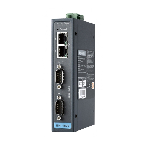
Introduction Advantech's EKI-1500 series of Industrial Device Servers are a robust, feature-rich, and cost effective way to network-enable equipment in an industrial automation envi- ronment. The EKI-1521/1522/1524 provides one, two, or four serial ports, two switched Ethernet ports, a wide range of power inputs, and a compact slim design, making them an ideal solution for connecting multiple asynchronous RS-232/422/485 serial devices to an Ethernet network. -
Page 9: Features
Serial Interface Interface: RS-232/422/485, software selectable No. of Ports: – EKI-1521: 1 – EKI-1522: 2 – EKI-1524: 4 Port Connector: DB9 male Baud Rate: 50 bps to 921.6 Kbps Parity: None, Even, Odd, Space, Mark Data bits: 5, 6, 7, 8 Stop bits: 1, 1.5, 2... -
Page 10: Package Check List
Software Utility: Advantech Serial Device Server Configuration Utility Driver support: Windows 2000/XP/Vista (x86) Operation Mode: – COM port redirection (Virtual COM) – TCP/UDP server (polling) mode – TCP/UDP client (event handling) mode – Pair connection mode Configuration: Web interface, Windows utility, Telnet console... -
Page 11: Chapter 2 Getting Started
Chapter Getting Started... -
Page 12: Understanding Eki-1521/1522/1524
Understanding EKI-1521/1522/1524 The EKI-1521/1522/1524 are network-based, serial device servers for connecting RS-232/422/485 devices, such as CNCs, PLCs, scales, and scanners, directly to a TCP/IP network. Once connected through EKI-1521/1522/1524, the serial device will be able to send and receive data on a network like any other network device. It extends traditional COM ports of a PC with access over a TCP/IP network. -
Page 13: Com Port Redirector (Virtual Com Port)
PC. The Advantech redirector can create up to 255 virtual COM ports. Application on the host can open virtual COM port to access the serial device servers at the same time. - Page 14 2.1.2.2 Multi-Access Mode (Shared COM port mode) Most of serial devices are connected directly and physically to the PC serial ports via a cable. The operation system, ex. Windows XP, provides the COM ports that user’s application can access, and control the serial device through the serial cable. This means that the serial device can be connected to one host and only one application on this host can handle input, output and control operation on this device.
-
Page 15: Tcp Server Mode
IP address and TCP port number of the network hosts which the EKI serial device server connect to using Advantech Serial Device Server Configuration Utility. After configuration, when EKI serial device server receives the data from serial port, the device server will employ the connection to hosts which are configured. -
Page 16: Serial Tunneling Mode
Two native serial devices can communicate over an Ethernet network without any intermediate host PC and software programming. Serial Tunneling is very simple to use. You can use Advantech Serial Device Server Configuration Utility to designate one serial port as the tunneling master and another serial device server port as the tunneling slave. -
Page 17: Hardware
LED Indicators There are LEDs display the power status, network status, and serial communication status located on the front panel of EKI-1521, EKI-1522, and EKI-1524, each of them has its own specific meaning as below table. Table 2.1: EKI-1521/1522/1524 LED Indicators... -
Page 18: Dimensions (Units: Mm)
2.2.2 Dimensions (Units: mm) 2.2.2.1 EKI-1521 and EKI-1522 Figure 2.7 Front View of EKI-1521/1522 Figure 2.8 Side View of EKI-1521/1522 EKI-1521/1522/1524 User Manual... - Page 19 Figure 2.9 Back View of EKI-1521/1522 Figure 2.10 Top View of EKI-1521/1522 EKI-1521/1522/1524 User Manual...
- Page 20 2.2.2.2 EKI-1524 Figure 2.11 Front View of EKI-1524 Figure 2.12 Side View of EKI-1524 EKI-1521/1522/1524 User Manual...
-
Page 21: Connecting Hardware
Figure 2.13 Back View of EKI-1524 Figure 2.14 Top View of EKI-1524 Connecting Hardware Next, we will explain how to find a proper location for your EKI-1521/1522/1524, and then explain how to connect to the network, hook up the power cable, and connect to the EKI-1521/1522/1524 serial port. - Page 22 2.3.1.1 Panel/Wall Mounting The EKI-1521/1522/1524 can be attached to a wall using the included metal brack- ets. Each bracket comes with four screws; and then you can install the device firmly via the components, please see the figure as below. Figure 2.15 Combine the Metal Mounting Kit 2.3.1.2 DIN Rail Mounting...
-
Page 23: Network Connection
Then, let the device down straight to slide over the rail smoothly. Figure 2.17 DIN-rail Step 2 2.3.2 Network Connection EKI-1521/1522/1524 has 2x RJ-45 that support connection to 10 Mbps Ethernet, or 100 Mbps Fast Ethernet, and half or full duplex operation. EKI-1521/1522/1524 can be connected to other hubs or switches through a twisted-pair straight through the cable or a crossover cable up to 100m long. -
Page 24: Serial Connection
DATA- DATA+ Installing the Configuration Utility The following section will show you how to install the Advantech serial device server configuration utility, a tool to set up and monitor the EKI-1500 serial device servers. Note! Be sure the Microsoft .NET Framework on your host PC is greater than version 2.0. - Page 25 Carefully read the Software License Agreement, and press "Yes" to continue. The Setup program will specify a default installation path: C:\Program Files\Advantech eAutomation\Serial Device Server Configuration Utility\ After setup has copied all program files to your computer, click the <Finish> but- ton to finish the installation.
- Page 26 EKI-1521/1522/1524 User Manual...
-
Page 27: Chapter 3 Configuration
Chapter Configuration... -
Page 28: Configuration Utility Overview
PC. With this secure func- tion enabled, other PCs will not have permission for configuration. After the installa- tion program on the Advantech IEDG Series Driver Utility CD-ROM is finished, the serial device servers will be ready for use and configure. -
Page 29: Discovering Serial Device Servers
3.2.1 Auto Searching Advantech Serial Device Server Configuration Utility will automatically search all the EKI-1000, ADAM-4570 and EDG-4500 series device servers on the network and show them on the Serial Device Server List Area of the utility. The utility provides an auto-search function to show your device(s) by simply executing the configuration utility program from the Start Menu. - Page 30 Select the device in this sub-tree. The first tab on the “Configuration Area” shows the summary of “Basic Information” included device type, version, and name, “Ethernet Information”, and “Serial Port Information”. In the serial port information frame, it dis- plays the operation mode, status and connected host IP. Click on the “+”...
-
Page 31: Clear Device List And Search Again
3.2.2 Clear Device List and Search Again You can click the button on the Quick Tool Bar. The utility will clear all list device servers in the Serial Device Server List Area and re-search again. Don’t use this function frequently. The warning message will be pop-up when you double click this button. -
Page 32: Manual Appending
3.2.3 Manual Appending Using “Add IP address to Favorite” or “Search a Range of IP addresses” function, you are able to add one device or group of devices to “Favorites”. These devices can locate on local network domain or other network domain. EKI-1521/1522/1524 User Manual... -
Page 33: Network Settings
Network Settings This section explains how to configure the EKI-1500 series network using this utility so that it can communicate over a network with serial devices. Click on the “+” before the model name (e.g. EKI-1524), and the utility will expand the tree structure to show the individual device name. -
Page 34: Serial Settings
DHCP + Auto-IP DHCP Server assigned IP address, Subnet Mask, Default Gateway, and DNS. BOOTP + Auto-IP BOOTP Server assigned IP address. DHCP + BOOTP + Auto-IP DHCP Server assigned IP address, Subnet Mask, Default Gateway, and DNS, or BOOTP Server assigned IP address. (If the DHCP Server does not respond) DNS Setting In order to use DNS feature, you need to set the IP address of the DNS server to be able to access the host with the domain name. - Page 35 Description: You can give a more detailed description on the function of the port for easier man- agement and maintenance. Descriptions have a limit of 128 characters. Type The EKI-1500 serial device server offers three kinds of serial interfaces, RS-232, RS- 485 and RS-422.
- Page 36 Data Bits: The EKI-1500 serial device server provides four options: 5, 6, 7 and 8. Stop Bits: The EKI-1500 serial device server provides three options: 1, 1.5 and 2. Flow Control: The EKI-1500 serial device server provides four options: None, XOn/XOff, RTS/CTS, and DTR/DSR.
- Page 37 Delay Time (ms) When you enable the delay time, the serial port will postpone the received data for the time interval you set, and then send the received data to the TCP/IP network. Ignore Purge Some application program will purge the serial port while it is the first time opens this serial port.
-
Page 38: Operation Mode Settings
Operation Mode Settings 3.5.1 Virtual COM Mode The EKI-1500 serial device server extends traditional COM ports of a PC to Ethernet access. Through Ethernet networking, users can control and monitor remote serial devices and equipments over LAN or WAN. The EKI-1500 series comes with a COM port redirector (Virtual COM driver) that transmits all serial signals intact. -
Page 39: Data Mode (Usdg Mode)
There are two operating mode of Multi-access function. One is Normal mode; another is Round-Robin mode. Normal mode Disabling “Response Timeout” parameter, the EKI-1500 series will operate in “normal mode”. When multiple hosts open the serial port simultaneously, the EKI-1500 series only offers control ability for the first connected host and provides data communica- tion function for others. - Page 40 You might select “USDG Mode” as the following figure to change the mode of the port to TCP server/client or UDP mode. Protocol The EKI-1500 series provides TCP/IP and UDP two protocols. In settings, you can choose either TCP mode or UDP mode according to your application. Data Listen Port The TCP/UDP port number represents the source port number, and the number is used to identify the channel for remote initiating connections.
- Page 41 Data Idle Timeout The default is 60 seconds. If you want to keep connection continually, you can disable the Data Idle Timeout. Data idle Time is the time period in which the device waits for data. If the EKI-1500 series does not receive data over an established idle time, the EKI-1500 series will disconnect temporarily.
-
Page 42: Control Mode (Usdg Mode)
Peer Number Set the number of network device which you want to connect. You can set maximum sixteen network devices which you want to connect. You need to fill out the IP Address and Port of network devices which you want to connect. 3.5.3 Control Mode (USDG Mode) In controlling mode, the EKI-1500 series presents a modem interface to the attached... - Page 43 The default value is 1000 ms. Example: <Guard Time> + <Guard Time> + <Guard Time> + The following commands are available for EKI-1500 series. Table 3.1: AT Command List Command Function ATDT<IP address> <TCP port> “Forms a TCP connection to the specified host. <CR>...
-
Page 44: Accessible Ip Settings
Accessible IP Settings Accessible IP setting allows you to add or remove the blocking host IP addresses to prevent unauthorized access. If you want to restrict access to certain PCs, you can list their IP addresses in this area. The maximum is 32 PCs. Auto Warning Settings 3.7.1 Email Alert... -
Page 45: Snmp Trap
3.7.2 SNMP Trap You need to set the proper IP address of SNMP Trap Server. And choose the Trap Version; there are “SNMP v1” and “SNMP v2c” options. 3.7.3 System Event Cold Start This refers to starting the system from power off. When performing a cold start, the EKI-1500 series will send an e-mail, or send a SNMP trap after success rebooting. -
Page 46: Serial Port Event
Warm Start This refers to restarting the system without turning the power off. When performing a warm start, the EKI-1500 series will send an e-mail, or send a SNMP trap after restarting the system. Authentication failure The user types a wrong password from Console or Administrator. When authentica- tion failure Occurs, the EKI-1500 series will send an e-mail, or send a SNMP trap. -
Page 47: Port Monitor
DCD Change The DCD (Data Carrier Detect) signal has changed, also indicating that the modem connection status has changed. For example, a DCD change to high also means “Connected” between local modem and remote modem. If the DCD signal changes to low, it also means that the connection line is down. -
Page 48: Administrator Settings
Administrator Settings The configuration utility provides several administrator settings for easy management and configuration. Right click the mouse on the device name in the sub-tree of Serial Device Sever List Area, and select these administrator settings. 3.9.1 Import/Export Device Setting The utility allows importing or exporting the serial device server’s setting via the “.conf”... -
Page 49: Import/Export Serial Port Setting
3.9.2 Import/Export Serial Port Setting The utility allows importing or exporting the serial port setting including “Basic Set- ting” and “Operation Setting” via “.sps” file format. 3.9.3 Locate the Serial Device Server If there are many serial device severs need your management, you may need to identify which unit is correct to configuration on utility. - Page 50 Click “Unlock Device” to unlock the serial device sever, and you need to fill in the password you have set up before. If you forgot the password, the only way to solve this problem is to restore the setting of the serial device server to the factory default which will be introduced next section.
-
Page 51: Restore To Factory Default Settings
3.9.5 Restore to Factory Default Settings The configuration utility provides this function to let you can restore the serial device server to factory default settings. The confirm message will be pop-up while clicking “Restore to Factory Default Settings”. If you really want to restore the serial device sever to factory default settings, please click “Yes”... -
Page 52: Update Firmware
3.9.6 Update Firmware Advantech continually upgrades its firmware to keep up with the ever-expending world of computing. You can use the update firmware function in the utility to carry out the upgrade procedure. Please access Advantech’s website: http://www.advan- tech.com to download the latest version of the firmware. Before update the firmware, make sure that your host’s Network domain is as same as the serial device server or... - Page 53 Wait for few seconds to process the updating firmware. After downloading the firm- ware completely, click on the “OK” button. The serial device server will restart auto- matically. Note! Be sure that the host PC Ethernet network domain is as same as the EKI-1500 serial device server or the host PC can establish the TCP con- nection with the serial device server while doing the updating firmware process.
- Page 54 EKI-1521/1522/1524 User Manual...
-
Page 55: Chapter 4 Setting Com Redirector
Chapter Setting COM Redirector... -
Page 56: Setting Com Redirector (Virtual Com Port)
Setting COM Redirector (Virtual COM port) Advantech COM port mapping software is a serial COM port redirector that creates virtual COM ports and provides access to serial devices connected to Advantech serial device servers. Your serial device applications can communicate with serial devices connected to Advantech serial device servers without software changes. - Page 57 The COM ports in the “Virtual Com Ports” listing are now available for use by Win- dows applications. EKI-1521/1522/1524 User Manual...
-
Page 58: Manual Mapping
4.1.2 Manual Mapping Right click the serial device name on the sub-tree of Device Server List area and select the “Manual Mapping” function. ADAM series, EDG series, and EKI wireless series have only one IP address. Select the serial port on the device server and the host COM that you want to set. Press <Map it>... - Page 59 Advantech serial device server. The function "Auto Reconnect" is for this purpose, if the Advantech serial server loses the connection to its host, the COM redirector will try to re-establish the connection while the host’s AP access the virtual COM port.
-
Page 60: Manual Direct Mapping Virtual Com Port
4.1.3 Manual Direct Mapping Virtual COM Port Click the button on the Quick Took area, you can add a target by selecting the Device Type and inputting the IP address without physically connecting the serial device server to the network. 4.1.4 Remove the Virtual COM Port If you want to remove the virtual COM port, you can remove them one by one or... -
Page 61: Running Diagnostic Test
Running Diagnostic Test The purpose of this test is to make sure the communication from host PC to EKI- 1521/1522/1524 is OK. If there is still an error, you can check the communication from the EKI-1521/1522/1524 to the devices. If the test is selected, an external test will be done to check that the connection signals for each port are working properly. - Page 62 Select which COM port you want to run a diagnostic test, and then press “Test” button to process the testing. Signal Test RTS -> CTS check the RTS and CTS signal between two ports DTR -> RI check the DTR and RI signal between two ports DTR ->...
-
Page 63: Chapter 5 Web-Based Configuration
Chapter Web-Based Configuration... -
Page 64: Overview
Overview EKI-1500 serial device server can be configured through a web interface. By using a standard web browser, the same procedure as with the Windows configuration utility can be used. In the browser’s address field, enter the IP Address of your EKI-1500 serial device server. - Page 65 By Windows Internet Explorer EKI-1521/1522/1524 User Manual...
-
Page 66: System
System You can change the Device Name and Device Description on this page. You can also enable or disable the Web, Telnet, and SNMP functions. Moreover, you can set the Timezone related setting. Network Configuration Click the Net Configuration and chose either Net 1 or Net 2, there are Net Mode, IP Address, Subnet Mask, Default Gateway and DNS. -
Page 67: Port Configuration
Note! All new configurations will take effect after rebooting. The reboot func- tion is located on the main menu of the Web Configuration. Port Configuration There are Basic, Operation Mode, and Advanced Setting in the serial port configuration. For more detailed information for setting, please refer to chapter 3.4 and chapter 3.5. -
Page 68: Monitor
Monitor You can monitor the serial ports settings, statistic, and the connected IP address by click on Monitor function on the main menu. EKI-1521/1522/1524 User Manual... -
Page 69: Auto Warning (Alarm)
Auto Warning (Alarm) You can set the e-mail server and SNMP Trap server in the Setting page, and set the event type in the Event page. For more detailed information for Auto Warning function, please refer to chapter 3.7. EKI-1521/1522/1524 User Manual... -
Page 70: Change Password
Note! All new configurations will take effect after rebooting. The reboot func- tion is located on the main menu of the Web Configuration. Change Password You can change the serial device server password on here: EKI-1521/1522/1524 User Manual... - Page 71 If you have set a password via the configuration utility or Telnet or serial console, when you access the web configuration, you need to key in the password. Do not need to enter the username in the dialog. If you want to disable the password protection, just change the password to the default “None”...
-
Page 72: Import/Export Device Settings
Import/Export Device Settings You can Import or Export the serial device server all setting as the “.conf” file format. EKI-1521/1522/1524 User Manual... -
Page 73: Reboot
5.10 Reboot The configuration will take effect after clicking “Save” button. But all configurations will save to flash memory after this reboot step. Press the “Reboot” button and the system will give a reset response. It will take a few seconds to reconnect with the new values. - Page 74 EKI-1521/1522/1524 User Manual...
-
Page 75: Chapter 6 Telnet Configuration
Chapter Telnet Configuration... -
Page 76: Overview
Overview The purpose of the Console Configuration is to help you manage your device in con- sole mode. One of the main functions of the console mode is to change the web con- figuration login password. You can use terminal software like Hyper Terminal, Telix and other related terminal software. -
Page 77: Command List
Connecting Success After connection the serial device server in Telnet console mode, you can see the welcome message in the Hyper Terminal Windows. Command List Table 6.1: Console Command List Command Function Description system Show or configure the system information port Show or configure the serial ports information portadv... - Page 78 Help You might type the “help” command or press <Tab> twice to show the supported command list. [Usage] help [Function] Display help information of command list You might use “help” command to show the usage of all commands. [Usage] help [command] [Function] Show the usage of command EKI-1521/1522/1524 User Manual...
- Page 79 System [Usage] system [Function] Show firmware version, device name and description [Usage] system [Function] Show current device status and information [Usage] system name XXXX [Function] Set current device name [XXXX: maximum length 31 bytes] [Usage] system desc XXXX [Function] Set current device description [XXXX: maximum length 127 bytes] Port “Port”...
- Page 80 [Usage] port nn or port all [Function] Show the “nn”th port or all ports information [Usage] port nn desc XXXX [Function] Set the “nn”th port’s description [XXXX: maximum length 127 bytes] EKI-1521/1522/1524 User Manual...
- Page 81 [Usage] port nn||all type 232|422|485 flow 0|1|2|3 [Function] Set serial ports’ type and flow control Flow 0: None Flow 1: XOn/XOff Flow2: RTS/CTS Flow3: DTR/DSR [Usage] port nn|all baud XXXX parity n|e|o|m|s data 5|6|7|8 stop 1|1.5|2 [Function] Set the serial ports’ baud rate, parity, data bits, and stop bits. Acceptable baud rate: 50, 75, 110, 150, 300, 600, 1200, 1800, 2400, 4800, 7200, 9600, 14400, 19200, 38400, 57600, 115200, 230400, 460800, and 921600 Parity n: None...
- Page 82 [Usage] mvcom [Function] Show all serial ports mode and related information [Usage] mvcom nn|all [Function] Set the “nn”th or all serial ports as the Virtual COM mode [Usage] mvcom nn|all idleto XX [Function] Set the “nn”th or all serial ports host idle timeout (S) [Usage] mvcom nn|all respto XX framebk XX [Function] Set the “nn”th or all serial ports response timeout and frame break mctrl...
- Page 83 mdata Show and setup the Data mode [Usage] mdata [Function] Show all serial ports mode and related information [Usage] mdata nn|all [Function] Set the “nn”th or all serial ports as the Data mode [Usage] mdata nn|all protocol TCP|UDP [Function] Set the “nn”th or all serial ports’ transmit protocol as TCP or UDP [Usage] mdata nn|all idleto XX lsport XXXX atport XXXX [Function] Set the “nn”th or all serial ports data idle timeout, listen port, and AT com- mand port...
- Page 84 Show and setup the Ethernet port configuration [Usage] net 1|2 [Function] Show the first or second Ethernet port status and information [Usage] net 1|2 mode static|dhcp|boot|all [Function] Set the network operating mode [Usage] net 1|2 ip XX.XX.XX.XX netmask XX.XX.XX.XX gw XX.XX.XX.XX [Function] Set IP address, subnet mask, and default gateway [Usage] net 1|2 dns auto|specific [Usage] net 1|2 dns1 XX.XX.XX.XX...
- Page 85 password [Usage] password new XXXX [Function] Set new password [XXXX: maximum 31 characters] [Usage] password old XXXX new XXXX [Function] Confirm the old password and set a new password apply [Usage] apply [Function] Save the settings to the flash memory and reboot the system immediately exit [Usage] exit [Function] Terminate the shell session...
- Page 86 monitor Show the serial ports settings, statistic, and connected IP address [Usage] monitor port 1|2|…|16 setting [Function] Monitor the serial ports settings [Usage] monitor port 1|2|…|16 statistic [Function] Monitor the serial ports statistic [Usage] monitor port 1|2…|16 ip [Function] Monitor the serial ports connected IP address EKI-1521/1522/1524 User Manual...
- Page 87 alarm Show or configure the auto warning function For more detailed setting for auto warning, please refer to chapter 3.7 time Show or configure the time information EKI-1521/1522/1524 User Manual...
- Page 88 [Usage] time [Function] Show the current time information [Usage] time YYYYMMDDhhmmss [Function] Modify the current time information [Usage] time timezone -12|…|0|1|…|12 [Function] Set the current timezone configuration [Usage] time daylight on|off begin MMDD end MMDD [Function] Set the current time daylight saving configuration [Usage] time ntp XXXX [Function] Set the NTP timeserver [XXXX: time server] service...
-
Page 89: Appendix A Pin Assignments
Appendix Pin Assignments... -
Page 90: Pin Assignments
Pin Assignments A.1.1 RS-232 Pin Assignments Pin # Description A.1.2 RS-422/485 Pin Assignments A.1.2.1 1. RS-422 Pin #. Description A.1.2.2 2. RS-485 Pin # Description Data- Data+ EKI-1521/1522/1524 User Manual... - Page 91 EKI-1521/1522/1524 User Manual...
- Page 92 No part of this publication may be reproduced in any form or by any means, electronic, photocopying, recording or otherwise, without prior written permis- sion of the publisher. All brand and product names are trademarks or registered trademarks of their respective companies. © Advantech Co., Ltd. 2007...
Need help?
Do you have a question about the EKI-1522 and is the answer not in the manual?
Questions and answers