Table of Contents
Advertisement
Quick Links
Advertisement
Table of Contents

Related Manuals for Advantech EKI-1528


Summary of Contents for Advantech EKI-1528
- Page 1 User Manual EKI-1528/1526 8/16-port RS-232/422/485 Serial Device Server...
- Page 2 No part of this manual may be reproduced, copied, translated or transmitted in any form or by any means without the prior written permission of Advantech Co., Ltd. Information provided in this manual is intended to be accurate and reliable. How- ever, Advantech Co., Ltd.
-
Page 3: Declaration Of Conformity
This product has passed the CE test for environmental specifications when shielded cables are used for external wiring. We recommend the use of shielded cables. This kind of cable is available from Advantech. Please contact your local supplier for ordering information. -
Page 4: Safety Instructions
The sound pressure level at the operator's position according to IEC 704-1:1982 is no more than 70 dB (A). DISCLAIMER: This set of instructions is given according to IEC 704-1. Advantech disclaims all responsibility for the accuracy of any statements contained herein. -
Page 5: Table Of Contents
2.3.2 Connecting EKI-1528/1526’s Power ........... 14 2.3.3 Connecting to the Serial Devices..........14 Table 2.2: EKI-1528/1526 Serial Port Pin Assignments .... 14 2.3.4 Connecting to a Host or the Network .......... 14 2.3.5 Connecting to the Serial Console Port........14 Installing the Configuration Utility............ - Page 6 Overview ....................68 Telnet Console..................68 Serial Console..................69 Command List..................71 Table 6.1: Console Command List ..........71 Appendix A Assignments....... 83 Pin Assignments ..................84 A.1.1 RS-232 Pin Assignments............84 A.1.2 RJ-45 Cable PIN Assignments ........... 84 EKI-1528/1526 User Manual...
-
Page 7: Chapter 1 Introduction
Chapter Introduction... -
Page 8: Overview
Overview This manual provides the necessary information to use the EKI-1528 and EKI-1526. The Advantech EKI-1500 series of serial device servers consist of fast and cost- effective device servers between serial RS-232/422/485 and Ethernet interfaces. The two Ethernet ports allow the EKI-1528/1526 to establish two separate Ethernet connections to two Ethernet domains or switches in the same domain. -
Page 9: Product Specifications
RS-485: Data+, Data-, GND Protection: 15 KV ESD protection for all signals 1.3.3 Software Features Driver Support: Windows 2000/XP/Vista(x86) Utility Software: Advantech Serial Device Server Configuration Utility Operation Modes: – COM port redirection mode (Virtual COM) – TCP/UDP server (polling) mode –... -
Page 10: General
1702002600: Power Cable US Plug 1.8m 1702002605: Power Cable EU Plug 1.8m 1702031801: Power Cable UK Plug 1.8m 1702031836: Power Cable China/Australia Plug 1.8m Note! If anything is missing or damaged, contact your distributor or sales rep- resentative immediately. EKI-1528/1526 User Manual... -
Page 11: Chapter 2 Getting Started
Chapter Getting Started... -
Page 12: Understanding The Eki-1528/1526
LAN or over the WAN. Since the EKI-1528/1526 is connected through a TCP/IP network, you might need to know some basic facts about networking in order to get the server hooked up correctly. -
Page 13: Com Port Redirector (Virtual Com)
PC. The Advantech redirector can create up to 255 virtual COM ports. Application on the host can open virtual COM port to access the serial device servers at the same time. -
Page 14: Tcp Server (Data Mode)
1500 serial device server. This operation mode supports a max. of 5 simultaneous connections for each serial port on the EKI-1500 serial device server from one host or several hosts, however multi-hosts collect the data from one serial port at the same time. EKI-1528/1526 User Manual... -
Page 15: Tcp Client (Data Mode)
EKI-1500 serial device servers to one host or sev- eral hosts. You should configure the IP address and TCP port number of the network hosts which the EKI-1500 serial device server connect to using Advantech Serial Device Server Configuration Utility. After configuration, when EKI-1500 serial device server receives the data from serial port, the device server will employ the connection to hosts which are configured. -
Page 16: Udp Mode (Data Mode)
EKI-1500 serial device server con- necting or disconnecting to remote networking devices. Thus intelligent serial devices such as stand-alone PLC will send /receive data to/from devices one by one via Ethernet. EKI-1528/1526 User Manual... -
Page 17: Hardware
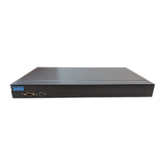
Hardware In this section, it will give you an overview of the EKI-1528/1526 hardware and installation. 2.2.1 Panel Layout EKI-1526: Front View EKI-1526: Rear View EKI-1528: Front View EKI-1528: Rear View Reboot Button Press the reboot button to reboot the EKI-1528/1526. -
Page 18: Led Indicators
LED Indicators There are LEDs display the power status, system status, dual Ethernet networks sta- tus, and serial communication status on the front panel of the EKI-1528/1526. Each of them has its own specific meaning as below table. Table 2.1: EKI-1528/1526 LED Indicators... -
Page 19: Connecting Hardware
Connecting Hardware This section introduces how to connect the EKI-1528 or EKI-1526 to serial devices for first time. 2.3.1 Rack Mount EKI-1528/1526 User Manual... -
Page 20: Connecting Eki-1528/1526'S Power
2.3.2 Connecting EKI-1528/1526’s Power Connect the EKI-1528 or EKI-1526 AC power line with its AC connector. If the power is properly supplied, you can turn on the power switch and the PWR LED will show a green color. 2.3.3 Connecting to the Serial Devices The EKI-1528/1526 provides 8 or 16 RJ45 connectors. -
Page 21: Installing The Configuration Utility
Installing the Configuration Utility The following section will show you how to install the Advantech serial device server configuration utility, a tool to set up and monitor the EKI-1500 serial device servers. Note! Be sure the Microsoft .NET Framework on your host PC is greater than version 2.0. - Page 22 The Setup program will specify a default installation path: C:\Program Files\Advantech eAutomation\Serial Device Server Configuration Utility\ After setup has copied all program files to your computer, click the <Finish> but- ton to finish the installation. EKI-1528/1526 User Manual...
-
Page 23: Chapter 3 Configuration
Chapter Configuration... -
Page 24: Configuration Utility Overview
PC. With this secure func- tion enabled, other PCs will not have permission for configuration. After the installa- tion program on the Advantech IEDG Series Driver Utility CD-ROM is finished, the serial device servers will be ready for use and configure. -
Page 25: Discovering Serial Device Servers
3.2.1 Auto Searching Advantech Serial Device Server Configuration Utility will automatically search all the EKI-1000, ADAM-4570 and EDG-4500 series device servers on the network and show them on the Serial Device Server List Area of the utility. The utility provides an auto-search function to show your device(s) by simply executing the configuration utility program from the Start Menu. - Page 26 Click on the “+” before the device name, and the utility will expand the interfaces on this device server. Click on each item, you will entry the configuration page to change the setting. The configuration will be introduced on following sections. EKI-1528/1526 User Manual...
-
Page 27: Clear Device List And Search Again
Serial Device Server List Area and re-search again. Don’t use this function frequently. The warning message will be pop-up when you double click this button. You can click the button on the “Quick Tool Bar”. The utility will search serial device server on local LAN. EKI-1528/1526 User Manual... -
Page 28: Manual Appending
Using “Add IP address to Favorite” or “Search a Range of IP addresses” function, you are able to add one device or group of devices to “Favorites”. These devices can locate on local network domain or other network domain. EKI-1528/1526 User Manual... -
Page 29: Network Settings
Network Settings This section explains how to configure the EKI-1528/1526 network using this utility so that it can communicate over a network with serial devices. Click on the “+” before the model name (e.g. EKI-1526), and the utility will expand the tree structure to show the individual device name. -
Page 30: Serial Settings
Serial Device Server. (Will reboot your Serial Device Server immediately) Serial Settings This section explains how to configure the EKI-1528/1526 serial communication parameters using this utility. There are various operation modes that are suitable for different application. - Page 31 The EKI-1500 serial device server supports baud rate from 50 to 921.6Kbps. While setting the baud rate, please note that the value should conform to the current trans- mission speeds of connected devices. Parity: The EKI-1500 serial device server provides five options: None, Odd, Even, Space, and Mark. EKI-1528/1526 User Manual...
- Page 32 Advanced Settings: The EKI-1500 serial device server provides the advanced settings for some special applications which need critical time requirements. In normal applications, these set- tings are recommended not to be set to avoid the unusual action happened. EKI-1528/1526 User Manual...
- Page 33 Enable this option will disable the multi-access function, thus the only one TCP con- nection is allowed on this serial port. Note! These settings are just for some special application cases. We recom- mend do not enable the advanced settings in normal usage. EKI-1528/1526 User Manual...
-
Page 34: Operation Mode Settings
The EKI-1500 serial device server extends traditional COM ports of a PC to Ethernet access. Through Ethernet networking, users can control and monitor remote serial devices and equipments over LAN or WAN. The EKI-1528/1526 comes with a COM port redirector (Virtual COM driver) that transmits all serial signals intact. This means that your existing COM-based software can be preserved, without modifying to fulfill the needs. -
Page 35: Data Mode (Usdg Mode)
Ethernet and the outputs of serial port are mixed. When the EKI-1528/1526 receives data from serial port, the data will also be transmitted to the connected hosts simultaneously. - Page 36 The default TCP/UDP port of the EKI-1528/1526 is 5300. The example initial 5300 is System Port, and 5301 is Data Port. But users can adjust them by one's preference or appli- cation.
- Page 37 Data Idle Timeout. Data idle Time is the time period in which the device waits for data. If the EKI-1528/1526 does not receive data over an established idle time, the EKI-1528/1526 will disconnect temporarily. When the data comes to the EKI-1528/1526, it will reconnect automatically.
-
Page 38: Control Mode (Usdg Mode)
The default character is “+”. After you have connected to another serial device via EKI-1528/1526, you may need to disconnect. Then you can use the command "+++" to disconnect. To do this leaves your keyboard idle (don't press any keys) for at least several seconds, then press "+"... -
Page 39: Table 3.1: At Command List
The default value is 1000 ms. Example: <Guard Time> + <Guard Time> + <Guard Time> + The following commands are available for EKI-1528/1526. Table 3.1: AT Command List Command Function ATDT<IP address> <TCP port> “Forms a TCP connection to the specified host. -
Page 40: Accessible Ip Settings
IP addresses in this area. The maximum is 32 PCs. Auto Warning Settings 3.7.1 Email Alert Consult your ISP or Network Administrator for the proper SMTP mail server settings. The auto warning functions may not work properly without proper settings. EKI-1528/1526 User Manual... -
Page 41: Snmp Trap
Version; there are “SNMP v1” and “SNMP v2c” options. 3.7.3 System Event Cold Start This refers to starting the system from power off. When performing a cold start, the EKI-1528/1526 will send an e-mail, or send a SNMP trap after success rebooting. EKI-1528/1526 User Manual... -
Page 42: Serial Port Event
Warm Start This refers to restarting the system without turning the power off. When performing a warm start, the EKI-1528/1526 will send an e-mail, or send a SNMP trap after restart- ing the system. Authentication failure The user types a wrong password from Console or Administrator. When authentica- tion failure Occurs, the EKI-1528/1526 will send an e-mail, or send a SNMP trap. -
Page 43: Port Monitor
For example, a DSR change to high also means that the DCE is powered ON. If the DSR signal changes to low, it also means that the DCE is powered off. When the DSR signal changes, the EKI-1528/1526 will send an e-mail, or send a SNMP trap. -
Page 44: Administrator Settings
Right click the mouse on the device name in the sub-tree of Serial Device Sever List Area, and select these administrator settings. 3.9.1 Import/Export Device Setting The utility allows importing or exporting the serial device server’s setting via the “.conf” file format. EKI-1528/1526 User Manual... -
Page 45: Import/Export Serial Port Setting
The configuration utility provides the “Lock Device” function to make it more confiden- tial. You need to set up a password while the first time clicking “Lock Device”. Be sure to click “Reset Device” to restart the serial device server and store your setting pass- word into the memory. EKI-1528/1526 User Manual... - Page 46 “None” (leave the new password and confirm new password columns blank) to disable this function or other password you want to change. Be sure to click “Reset Device” to restart the serial device sever and store the new password into the memory. EKI-1528/1526 User Manual...
-
Page 47: Restore To Factory Default Settings
Then, please power off the serial device server within ten seconds, after reconnect- ing the power back, the all setting will be reset to the factory default. If the power remains more than ten seconds, the serial device server will not have any changes. EKI-1528/1526 User Manual... -
Page 48: Update Firmware
3.9.6 Update Firmware Advantech continually upgrades its firmware to keep up with the ever-expending world of computing. You can use the update firmware function in the utility to carry out the upgrade procedure. Please access Advantech’s website: http://www.advan- tech.com to download the latest version of the firmware. Before update the firmware, make sure that your host’s Network domain is as same as the serial device server or... - Page 49 Be sure that the host PC Ethernet network domain is as same as the EKI-1500 serial device server or the host PC can establish the TCP con- nection with the serial device server while doing the updating firmware process. EKI-1528/1526 User Manual...
- Page 50 EKI-1528/1526 User Manual...
-
Page 51: Setting Com Redirector
Chapter Setting COM Redirector... -
Page 52: Setting Com Redirector(Virtual Com Port)
Setting COM Redirector(Virtual COM port) Advantech COM port mapping software is a serial COM port redirector that creates virtual COM ports and provides access to serial devices connected to Advantech serial device servers. Your serial device applications can communicate with serial devices connected to Advantech serial device servers without software changes. - Page 53 The COM ports in the “Virtual Com Ports” listing are now available for use by Win- dows applications. EKI-1528/1526 User Manual...
-
Page 54: Manual Mapping
Right click the serial device name on the sub-tree of Device Server List area and select the “Manual Mapping” function. Select the serial port on the serial device server and the host COM that you want to map. Press <Map it> to establish the virtual COM port on the host. EKI-1528/1526 User Manual... - Page 55 Advantech serial device server. The function "Auto Reconnect" is for this purpose, if the Advantech serial server loses the connection to its host, the COM redirector will try to re-establish the connection while the host’s AP access the virtual COM port.
-
Page 56: Manual Direct Mapping Virtual Com Port
Remove the Virtual COM Port If you want to remove the virtual COM port, you can remove them one by one or group remove ports. Individual Remove Right click on COM port you have mapped before and select “Remove This Port”. EKI-1528/1526 User Manual... -
Page 57: Running Diagnostic Test
RS-232 mode. The test is divided into two parts: Signal test and Communication Parameters test. Note! Before you do this diagnostic test, you must complete the process of vir- tual COM port mapping (which is described in chapter 4.1). EKI-1528/1526 User Manual... - Page 58 Click “Simple Serial Test” on the Tools menu, Select which COM port you want to run diagnostic test, and then press “Test” button to process the testing. EKI-1528/1526 User Manual...
- Page 59 Data bit: 5, 6, 7, 8 Stop bit: 1, 1.5, 2 Parity: Odd, Even, None, Space, Mark When the test is finish, it will show the test result, the click “Exit” button to return to the utility window. EKI-1528/1526 User Manual...
- Page 60 EKI-1528/1526 User Manual...
-
Page 61: Web-Based Configuration
Chapter Web-Based Configuration... -
Page 62: Overview
Before using the web-based configuration, make sure your host PC Ethernet network IP domain is as same as the serial device server, or it can establish the TCP connection with the serial device server. Accessing the Web Page By configuration utility EKI-1528/1526 User Manual... - Page 63 By Windows Internet Explorer EKI-1528/1526 User Manual...
-
Page 64: System
Click the Net Configuration and chose either Net 1 or Net 2, there are Net Mode, IP Address, Subnet Mask, Default Gateway and DNS. Enter the corresponding values for your network environment. Remember press “Save” after fill in all values. EKI-1528/1526 User Manual... -
Page 65: Port Configuration
Web Configuration. Port Configuration There are Basic, Operation Mode, and Advanced Setting in the serial port configuration. For more detailed information for setting, please refer to chapter 3.4 and chapter 3.5. EKI-1528/1526 User Manual... -
Page 66: Monitor
Monitor You can monitor the serial ports settings, statistic, and the connected IP address by click on Monitor function on the main menu. EKI-1528/1526 User Manual... -
Page 67: Auto Warning (Alarm)
Auto Warning (Alarm) You can set the e-mail server and SNMP Trap server in the Setting page, and set the event type in the Event page. For more detailed information for Auto Warning function, please refer to chapter 3.7. EKI-1528/1526 User Manual... -
Page 68: Change Password
Note! All new configurations will take effect after rebooting. The reboot func- tion is located on the main menu of the Web Configuration. Change Password You can change the serial device server password on here: EKI-1528/1526 User Manual... - Page 69 If you want to disable the password protection, just change the password to the default “None” (leave the new password column blank), Be sure to press the “Save” button and reboot the serial device server to make the change effective. EKI-1528/1526 User Manual...
-
Page 70: Import/Export Device Settings
Import/Export Device Settings You can Import or Export the serial device server all setting as the “.conf” file format. EKI-1528/1526 User Manual... -
Page 71: Reboot
The configuration will take effect after clicking “Save” button. But all configurations will save to flash memory after this reboot step. Press the “Reboot” button and the system will give a reset response. It will take a few seconds to reconnect with the new values. EKI-1528/1526 User Manual... - Page 72 EKI-1528/1526 User Manual...
- Page 73 Chapter Telnet/Serial Console Configuration...
-
Page 74: Overview
Input the IP address Confirm that the Telnet console configuration works ok. Be sure that your host PC Ethernet network IP domain is as same as the EKI-1500 serial device server, and the Telnet TCP port number is “23”. EKI-1528/1526 User Manual... -
Page 75: Serial Console
Make sure the connection is OK and then run the Hyper Terminal Program on your host. Create a new connection You can create a new connection and assign a connection name for the console con- figuration. EKI-1528/1526 User Manual... - Page 76 To connect the EKI-1500 serial device server for console configuration, the port set- ting should match the EKI-1500 serial device sever default settings. Console Configuration Default Settings Baud rate: 38400 Data bits: 8 Parity: None Stop bits: 1 Flow control: None EKI-1528/1526 User Manual...
-
Page 77: Command List
Monitor the serial ports status alarm Show or configure the auto warning functions including mail alarm and SNMP alarm time Show or configure the time information service Enable or disable the web, Telnet and SNMP functions EKI-1528/1526 User Manual... - Page 78 You might type the “help” command or press <Tab> twice to show the supported command list. [Usage] help [Function] Display help information of command list You might use “help” command to show the usage of all commands. [Usage] help [command] [Function] Show the usage of command EKI-1528/1526 User Manual...
- Page 79 [Function] Set current device name [XXXX: maximum length 31 bytes] [Usage] system desc XXXX [Function] Set current device description [XXXX: maximum length 127 bytes] Port “Port” is the command to show all serial ports information and configure the serial ports settings. EKI-1528/1526 User Manual...
- Page 80 [Usage] port nn or port all [Function] Show the “nn”th port or all ports information [Usage] port nn desc XXXX [Function] Set the “nn”th port’s description [XXXX: maximum length 127 bytes] EKI-1528/1526 User Manual...
- Page 81 Parity e: Even Parity o: Odd Parity m: Mark Parity s: Space [Usage] port nn|all mode vcom|ctrl|data [Function] Set the serial ports as virtual COM mode, control mode, or data mode mvcom Show and setup the VCOM mode EKI-1528/1526 User Manual...
- Page 82 [Function] Set the “nn”th or all serial ports as the Control mode [Usage] mctrl nn|all idleto XX guardt XX hangchr XX [Function] Set the “nn”th or all serial ports data idle timeout, guard time and hang character EKI-1528/1526 User Manual...
- Page 83 [Usage] mdata nn|all respto XX framebk XX [Function] Set the “nn”th or all serial ports response timeout and frame break [Usage] mdata nn|all peernum 1|2|3|4|5|6|7|8|9|10|11|12|13|14|15|16 peer XX.XX.XX.XX:ppp [Function] Set the peer IP address and port for receive data EKI-1528/1526 User Manual...
- Page 84 [Usage] net 1|2 ip XX.XX.XX.XX netmask XX.XX.XX.XX gw XX.XX.XX.XX [Function] Set IP address, subnet mask, and default gateway [Usage] net 1|2 dns auto|specific [Usage] net 1|2 dns1 XX.XX.XX.XX [Usage] net 1|2 dns2 XX.XX.XX.XX [Function] Set the DNS function EKI-1528/1526 User Manual...
- Page 85 [Function] Save the settings to the flash memory and reboot the system immediately exit [Usage] exit [Function] Terminate the shell session import/export [Usage] import [Function] Import the serial device server settings’ file [Usage] export [Function] Export the serial device server settings’ file EKI-1528/1526 User Manual...
- Page 86 [Function] Monitor the serial ports settings [Usage] monitor port 1|2|…|16 statistic [Function] Monitor the serial ports statistic [Usage] monitor port 1|2…|16 ip [Function] Monitor the serial ports connected IP address alarm Show or configure the auto warning function EKI-1528/1526 User Manual...
- Page 87 For more detailed setting for auto warning, please refer to chapter 3.7 time Show or configure the time information EKI-1528/1526 User Manual...
- Page 88 Enable or disable some extra service [Usage] service web enable|disable [Function] Enable or disable the web-based configuration [Usage] service telnet enable|disable [Function] Enable or disable the telnet console [Usage] service SNMP enable|disable [Function] Enable or disable the SNMP function EKI-1528/1526 User Manual...
-
Page 89: Appendix A Pin Assignments
Appendix Pin Assignments... -
Page 90: Pin Assignments
Pin Assignments A.1.1 RS-232 Pin Assignments A.1.2 RJ-45 Cable PIN Assignments A.1.2.1 1. RS-422 Pin No. Description A.1.2.2 2. RS-485 Pin No. Description Data- Data+ EKI-1528/1526 User Manual... - Page 91 EKI-1528/1526 User Manual...
- Page 92 No part of this publication may be reproduced in any form or by any means, electronic, photocopying, recording or otherwise, without prior written permis- sion of the publisher. All brand and product names are trademarks or registered trademarks of their respective companies. © Advantech Co., Ltd. 2008...
Need help?
Do you have a question about the EKI-1528 and is the answer not in the manual?
Questions and answers