Table of Contents
Advertisement
Quick Links
Advertisement
Table of Contents

Subscribe to Our Youtube Channel
Related Manuals for Advantech EKI-1500 Series


Summary of Contents for Advantech EKI-1500 Series
- Page 1 User Manual EKI-1500 Series 1/2/4-port RS-232/422/485 Serial Device Servers...
- Page 2 No part of this manual may be reproduced, copied, translated or transmitted in any form or by any means without the prior written permission of Advantech Co., Ltd. Information provided in this manual is intended to be accurate and reliable. How- ever, Advantech Co., Ltd.
-
Page 3: Declaration Of Conformity
This product has passed the CE test for environmental specifications when shielded cables are used for external wiring. We recommend the use of shielded cables. This kind of cable is available from Advantech. Please contact your local supplier for ordering information. -
Page 4: Document Feedback
1 x EKI-1521 or EKI-1522 or EKI-1524 serial device server 1 x Terminal Block 1 x Document and software CD 2 x Wall/panel mount kit 1 x RS-232 loopback DB9 tester EKI-1500 Series User Manual... -
Page 5: Safety Instructions
STORAGE TEMPERATURE MAY GO BELOW -40°C (-40°F) OR ABOVE 75°C (167°F). THIS COULD DAMAGE THE EQUIPMENT. THE EQUIPMENT SHOULD BE IN A CONTROLLED ENVIRONMENT. This is building-in equipment and shall be installed in a suitable enclosure. Warning! Hot surface. Do not touch. EKI-1500 Series User Manual... - Page 6 Don't touch any components on the CPU card or other cards while the PC is on. Disconnect power before making any configuration changes. The sudden rush of power as you connect a jumper or install a card may damage sensitive elec- tronic components. EKI-1500 Series User Manual...
-
Page 7: Table Of Contents
Figure 2.16 Wall Mount Installation ........... 17 2.3.2 Serial Connection................ 18 Figure 2.17 DB9 Pin Assignment..........18 2.3.3 Power Connection............... 18 Figure 2.18 Power Wiring for EKI-1500 Series......19 Chapter Utility Configuration ......20 Installing the Configuration Utility............21 Figure 3.1 InstallShield Wizard 1 of 4 ........ - Page 8 Viewing Manual VCOM Mapping Results ....47 5.2.3 Configuration Wizard ..............47 Figure 5.8 Selecting the Configuration Wizard ......47 5.2.4 Confirming Virtual COM Settings..........48 Figure 5.9 Serial Port Listing on EKI Device ......48 EKI-1500 Series User Manual viii...
- Page 9 6.10.2 Change Password............... 67 Figure 6.17 Management > Change Password ......67 6.10.3 Export Device Settings..............67 Figure 6.18 Management > Export ..........67 6.10.4 Import Device Settings..............67 Figure 6.19 Management > Import ..........67 EKI-1500 Series User Manual...
- Page 10 7.3.13 mrfc2217..................75 7.3.14 apply ................... 75 7.3.15 exit ....................75 7.3.16 help ..................... 75 7.3.17 reboot..................75 Chapter A TCP and UDP Port Numbers .... 76 List of Known TCP and UDP Port Numbers ........... 77 EKI-1500 Series User Manual...
-
Page 11: Chapter 1 Introduction
Chapter Introduction... -
Page 12: Overview
TCP/IP network. Through networking, you can control and moni- tor remote serial devices over either a LAN or WAN. Since the EKI-1500 Series is connected through a TCP/IP network, you may need to know some basic facts about networking in order to connect the server correctly. -
Page 13: Chapter 2 Getting Started
Chapter Getting Started... -
Page 14: Specifications
Protection Built-in 15 KV ESD for all signals 'CI' models: 2KV Isolation for RS-422/485 signals Power Power EKI-1521: 5.2W Consumption EKI-1522: 5.2W EKI-1524: 6.3W Power Input 12 ~ 48V , redundant dual inputs EKI-1500 Series User Manual... - Page 15 Specifications Description Software Driver Support 32-bit/64-bit Windows XP/Vista/7/8/8.1/10, Windows Server 2003/2008/2008 R2/2012/2012 R2, and Linux Utility Advantech EKI Device Configuration Utility Operation Modes COM port redirection mode (Virtual COM) TCP/UDP server (polling) mode TCP/UDP client (event handling) mode ...
-
Page 16: Hardware
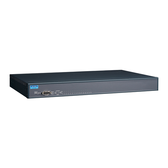
The following view shows the EKI-1521. P2 Status Default EKI-1521 Figure 2.1 Front View No. Item Description System LED panel See “LED Indicators” on page 11 for further details. ETH port RJ45 ports x 2 Serial port DB9 pinout, supports RS-232/422/485 EKI-1500 Series User Manual... -
Page 17: Figure 2.2 Front View
The following view shows the EKI-1522. P2 Status Default EKI-1522 Figure 2.2 Front View No. Item Description System LED panel See “LED Indicators” on page 11 for further details. ETH port RJ45 ports x 2 Serial port DB9 pinout, supports RS-232/422/485 EKI-1500 Series User Manual... -
Page 18: Figure 2.3 Front View
P2 Status Default Serial ports EKI-1524 Figure 2.3 Front View No. Item Description System LED panel See “LED Indicators” on page 11 for further details. ETH port RJ45 ports x 2 Serial port DB9 pinout, supports RS-232/422/485 EKI-1500 Series User Manual... -
Page 19: Rear View
2.2.2 Rear View The following view is valid for the EKI-1521 and EKI-1522. Figure 2.4 Rear View No. Item Description DIN-Rail mounting Mounting plate used for the installation to a standard DIN rail plate EKI-1500 Series User Manual... -
Page 20: Top View
Figure 2.6 Top View No. Item Description Terminal block Connect cabling for power and alarm wiring Ground terminal Screw terminal used to ground chassis Wall mounting holes Screw holes (x4) used in the installation of a wall mounting plate EKI-1500 Series User Manual... -
Page 21: Led Indicators
Power 2 is on Power 2 is off, or power error condition exists Status Amber The device server has been located by utility’s loca- tion function Amber, blinking System is ready (1cycle/sec.) System is not working EKI-1500 Series User Manual... -
Page 22: Dimensions
2.2.5 Dimensions The following view is valid for the EKI-1521 and EKI-1522. Unit: mm 36.60 30.50 Figure 2.9 Dimensions EKI-1500 Series User Manual... -
Page 23: Figure 2.10 Dimensions
The following view is valid for the EKI-1524. 30.5 Unit: mm 48.60 30.50 Figure 2.10 Dimensions EKI-1500 Series User Manual... -
Page 24: Connecting Hardware
Align the mounting bracket on the rear side. The screw holes on the device and the mounting bracket must be aligned, see the following illustration. Secure the mounting bracket with M3 screws, see the following figure. Figure 2.11 Installing the Mounting Bracket EKI-1500 Series User Manual... -
Page 25: Figure 2.12 Installing The Din-Rail Mounting Kit
Rotate the bottom of the device towards you and away from the DIN rail. Once the bottom is clear of the DIN rail, lift the device straight up to unhook it from the DIN rail. DIN Rail Figure 2.13 Removing the DIN-Rail EKI-1500 Series User Manual... -
Page 26: Figure 2.14 Installing Wall Mount Plates
Secure the wall mount plates with M3 screws, see the following figure. Figure 2.14 Installing Wall Mount Plates Once the wall mounting plates are secure on the device, you will need to attach the wall screws (x8). EKI-1500 Series User Manual... -
Page 27: Figure 2.15 Securing Wall Mounting Screws
Install the wall mount plate on the screws and slide it forward to lock in place, see the following figure. Figure 2.16 Wall Mount Installation Once the device is installed on the wall, tighten the screws to secure the device. EKI-1500 Series User Manual... -
Page 28: Serial Connection
Caution! Disconnect the power cord before installation or cable wiring. The EKI-1500 Series supports dual 12 to 48 VDC power inputs and power-fail relay output. EKI-1500 Series User Manual... -
Page 29: Figure 2.18 Power Wiring For Eki-1500 Series
Load Power Figure 2.18 Power Wiring for EKI-1500 Series You can connect an alarm indicator, buzzer or other signaling equipment through the relay output. The relay opens if power input 1 or 2 fails. In a wiring example where an LED is connected to the relay output, the LED would be off in an Open state. -
Page 30: Chapter 3 Utility Configuration
Chapter Utility Configuration... -
Page 31: Installing The Configuration Utility
Microsoft.NET Framework version 2.0 or greater is required for this application. Insert the Advantech EKI Device Configuration Utility CD-ROM into the CD- ROM drive (whereas E:\ is the drive name of your CD-ROM) on the host PC. Use Windows explorer or the Windows Run command to execute the setup pro- gram, the path for the setup program on the CD-ROM is as follows: E:\EKI_Device_Configuration_Utility_v2.01.exe... -
Page 32: Figure 3.2 Installshield Wizard 2 Of 4
Figure 3.2 InstallShield Wizard 2 of 4 The InstallShield continues and a status screen displays. The default installation path is C:\Program Files\EKI Device Configuration Utility. Figure 3.3 InstallShield Wizard 3 of 4 EKI-1500 Series User Manual... -
Page 33: Figure 3.4 Installshield Wizard 4 Of 4
Once the installation of the package is finished a Configuration Utility Setup screen displays. Click Finish to conclude the process and exit the InstallShield Wizard. Figure 3.4 InstallShield Wizard 4 of 4 EKI-1500 Series User Manual... -
Page 34: Starting The Configuration Utility
PC. With this secure function enabled, other PCs will not have permission for configuration. After the installation program on the Advantech IEDG Series Driver Utility CD-ROM is fin- ished, the serial device servers are ready for use and configuration. -
Page 35: Discovering Your Device Server
Auto Searching Advantech Serial Device Server Configuration Utility will automatically search all the EKI-1500 Series device servers on the network and show them on the Serial Device Server List Area of the utility. The utility provides an auto-search function to show your device (s) by simply executing the configuration utility program from the Start Menu. -
Page 36: Figure 3.7 Selecting A Group
Click on the “+” before the device name, and the utility will expand the interfaces on this device server. Figure 3.8 Selecting a Device Click on each item to enter the configuration page to change the setting. The configu- ration will be introduced on following sections. Figure 3.9 Viewing Basic Settings EKI-1500 Series User Manual... -
Page 37: Network Settings
The EKI series includes a software utility option, which you can install on your sys- tem, for configuration through computer-based software. The EKI series also includes a web interface option for configuration through a standard web browser. Figure 3.10 Utility Overview EKI-1500 Series User Manual... -
Page 38: Figure 3.11 Network Settings Overview
DHCP server to give IP within DHCP time out. The default value is 180 seconds. Note! When you have finished the configuration of these settings for each cat- egory, please press the “Apply” button in order to make these settings effective on the Serial Device Server. EKI-1500 Series User Manual... -
Page 39: Administrator Settings
From the device list frame, locate the desired device and right-click on it to dis- play the settings menu. Select Locate from the menu. Figure 3.12 Locate the Serial Device Server The unit’s Status LED will turn solid amber and the buzzer will sound until you click Stop Locate. EKI-1500 Series User Manual... -
Page 40: Securing The Serial Device Server
Right-click a desired device to display the settings menu. Select Lock Device. Figure 3.13 Lock the Serial Device Server Enter a password. Retype the password entry to confirm the profile password. Figure 3.14 Enter a Password EKI-1500 Series User Manual... -
Page 41: Figure 3.15 Reset Device
Enter the password as entered in the Lock Device procedure. Figure 3.16 Unlock the Serial Device Server If you forgot the password, you must restore the setting of the serial device server to the factory defaults, which will be introduced in the next section. EKI-1500 Series User Manual... -
Page 42: Restore To Factory Default Settings
Power off the serial device server within ten seconds. After reconnecting the power, all settings will be reset to the factory default. If the power supply remains connected for more than ten seconds, the serial device server will not be changed. EKI-1500 Series User Manual... -
Page 43: Resetting The Device
Right-click a desired device to display the settings menu. Select Reset Device. Figure 3.18 Reset Device The device resets. Once the process is complete, the serial device server displays under the Serial Device Server listing once again. EKI-1500 Series User Manual... -
Page 44: Add To Favorite
EKI devices. Figure 3.19 Add to Favorite 3.4.6 Auto Mapping See “Auto Mapping” on page 44 for further details. 3.4.7 Manual Mapping See “Manual Mapping” on page 46 for further details. EKI-1500 Series User Manual... -
Page 45: Update Firmware
Note! Be sure that the host PC Ethernet network domain is as same as the EKI-1500 Series serial device server or the host PC can establish the TCP connection with the serial device server while doing the updating firmware process. -
Page 46: Selecting An Operating Mode
Chapter Selecting An Operating Mode... -
Page 47: Overview
PC. The Advantech redirector can create up to 255 virtual COM ports. Application to the host can open a virtual COM port to access the serial device servers at the same time. -
Page 48: Normal Mode
Ethernet and the outputs of serial port are mixed. When the EKI-1500 Series receives data from serial port, the data will also be transmitted to the connected hosts simultaneously. -
Page 49: Usdg Data Mode
USDG Data Mode The EKI-1500 Series can funciton as either a Data TCP server or a Data TCP client. Both operations support TCP and UDP protocol. The EKI-1500 Series allows you to treat your serial devices as if they were networking devices. You can issue com- mands or transmit data from serial devices, connected to a EKI-1500 Series device, to any devices that are connected to the Internet. -
Page 50: Usdg Data Tcp Server Mode
Data Idle Timeout. Data idle Time is the time period for which the device waits for data. If the EKI-1500 Series does not receive data during established idle time, the EKI-1500 Series will disconnect temporarily. When the data comes in, it will reconnect automatically. -
Page 51: Usdg Control Mode
The default TCP/UDP port of the EKI-1500 Series Port1 is 5300, Port2 is 5301, etc. Users can adjust them according to preference or application. Each port has its own data listen port to accept the connection requests of other network device. -
Page 52: Guard Time
EKI-1500 Series devices to a local COM port on a host computer. RFC2217 defines general COM port control options based on the Telnet protocol. -
Page 53: Setting Up Virtual Com Port
Chapter Setting up Virtual COM Port... -
Page 54: Setting Com Port Redirector
Setting COM Port Redirector Advantech COM port mapping software is a serial COM port redirector that creates virtual COM ports and provides access to serial devices connected to an Advantech serial device servers. Your serial device applications can communicate with serial devices connected to the Advantech serial device servers without software changes. -
Page 55: Figure 5.2 Selecting Auto Mapping
Figure 5.3 Mapping Selected Ports Once the mapping function is initialized, a successful mapping process results in the virtual mapping of the designated physical serial port and VCOM PC port. See the following figure. Figure 5.4 Viewing VCOM Mapping Results EKI-1500 Series User Manual... -
Page 56: Manual Mapping
Manual Mapping On your desktop, navigate to Start > All Programs > EKI Device Configura- tion Utility and click Advantech EKI Device Configuration Utility to open the utility. Under Serial Device Servers, locate your server and click the icon to expand the listing. -
Page 57: Configuration Wizard
Configuration Wizard On your desktop, navigate to Start > All Programs > EKI Device Configura- tion Utility and click Advantech EKI Device Configuration Utility to open the utility. Under Serial Device Servers, locate your server and click the icon to expand the listing. -
Page 58: Confirming Virtual Com Settings
Confirming Virtual COM Settings On your desktop, navigate to Start > All Programs > EKI Device Configura- tion Utility and click Advantech EKI Device Configuration Utility to open the utility. Locate Serial Ports menu in the menu pane and click on the Expand icon next to Virtual COM Ports to view a list of the mapped ports. -
Page 59: Figure 5.10 System Port Vcom Mapping Configuration
EKI device, see the following figure. Figure 5.11 Verifying VCOM Mapping Configuration If the settings do not correspond, the VCOM mapping is not correct. See “Virtual COM Port Mapping” on page 44 to re-map the VCOM ports. EKI-1500 Series User Manual... -
Page 60: Removing Vcom Ports
Removing VCOM Ports On your desktop, navigate to Start > All Programs > EKI Device Configura- tion Utility and click Advantech EKI Device Configuration Utility to open the utility. Under Serial Ports, click the expand icon on Virtual COM Ports to view the con- figured port list. -
Page 61: Running A Diagnostic Test
Connect the loopack connector to a COM port on the EKI serial device server. On your desktop, navigate to Start > All Programs > EKI Device Configura- tion Utility and click Advantech EKI Device Configuration Utility to open the utility. -
Page 62: Chapter 6 Web Interface
Chapter Web Interface... -
Page 63: Overview
Overview EKI-1500 Series serial device server can be configured through a web interface. By using a standard web browser, the same procedure as with the Windows configura- tion utility can be used. In the browser’s address field, enter the IP Address of your EKI-1500 Series serial device server. -
Page 64: Accessing The Web Page Via Web Browser
Click Enabled or Disabled to enable or disable the daylight saving time settings. Begin Time Set the time and date on which daylight saving begins. End Time Set the time and date on which daylight saving ends. EKI-1500 Series User Manual... -
Page 65: Ethernet Configuration
Displays the current IP address 2 of the device. Save Click Save to save the values and update the screen. Note! All new configurations will take effect after rebooting. To reboot the device, click Tools > Reboot. EKI-1500 Series User Manual... -
Page 66: Port Configuration
Click the drop-down menu to select the stop bits: 1, 1.5 or 2. Flow Control Click the drop-down menu to select the flow control mode: None, XOn/XOff, RTS/CTS or DTR/DSR Save Click Save to save the values and update the screen. EKI-1500 Series User Manual... -
Page 67: Operation
Click the drop-down menu to select port data buffering type: None or RAM. When Data Full Click the drop-down menu to select process mode when data full: Stop. Save Click Save to save the values and update the screen. EKI-1500 Series User Manual... -
Page 68: Advanced
Click the option to determines the maximum characters will be wrote into one interrupt. USDG Advanced Options (Flow Control will overwrite these options) RTS Control Click the drop-down menu to select the status of RTS: ON, OFF, Toggle By Connect or Toggle By Data. EKI-1500 Series User Manual... -
Page 69: Monitor
Display the current RTS/CTS status of the selected port. XON/XOFF Display the current XON/OFF status of the selected port. DTR/DSR Display the current DTR/DSR status of the selected port. Save Click Save to save the values and update the screen. EKI-1500 Series User Manual... -
Page 70: Statistic
Display the current DTR status of the selected port. Display the current DSR status of the selected port. Display the current DCD status of the selected port. Save Click Save to save the values and update the screen. EKI-1500 Series User Manual... -
Page 71: Connected Ip
The SNMP Trap Server settings allows you to specify the management station of a significant event by way of an unsolicited SNMP message. The Simple Network Management Protocol (SNMP) is used by the serial device server to collect detailed information about the serial device server. EKI-1500 Series User Manual... -
Page 72: Figure 6.10 Alarm > Setting
Enter the write-only, private, community string. Contact Enter the individual designated the contact point for this event. Location Enter the designated location/department of the setting. Save Click Save to save the values and update the screen. EKI-1500 Series User Manual... -
Page 73: Event
Click the option to select a warning type of the selected port when a change in the DSR (Data Set Ready) signal indicates that the data communication equipment is powered off. Save Click Save to save the values and update the screen. EKI-1500 Series User Manual... -
Page 74: Syslogd
Click Save to save the values and update the screen. 6.8.2 Syslogd Message After enabling the syslogd function, users can check the history in the syslogd mes- sage page. To access this page, click Syslogd > Syslogd Message. Figure 6.13 Syslogd > Syslogd Message EKI-1500 Series User Manual... -
Page 75: Tools
Enter the number of echo requests to send. The default value is 4. The value ranges from 1 to 5. The count entered is not retained across a power cycle. Run ping Display the ping reply format. EKI-1500 Series User Manual... -
Page 76: Reboot
System Log File Click the drop-down menu to select a specific action for the system log file. Available options: Download System Log, Remove System Log, Download and Remove System Log. Export Click Export to download the log file. EKI-1500 Series User Manual... -
Page 77: Change Password
To access this page, click Management > Import. Figure 6.19 Management > Import The following table describes the items in the previous figure. Item Description Choose File Click Choose File to select the configuration file. Submit Click Submit to backup the settings. EKI-1500 Series User Manual... -
Page 78: Telnet/Serial Console Configuration
Chapter Telnet/Serial Console Configuration... -
Page 79: Overview
You can use terminal software like Hyper Terminal, Telix and other related terminal software. Telnet Console 7.2.1 Create a new connection You can create a new Telnet connection and assign a connection name for the con- sole configuration. Figure 7.1 Creating a Telnet Connection EKI-1500 Series User Manual... -
Page 80: Input The Ip Address
Figure 7.3 Telnet Connection Console At the command prompt, you can type a “help” followed by the Enter button, or <Tab> twice, to display the command list. You can toggle between the different command menu options. EKI-1500 Series User Manual... -
Page 81: Command List
Acceptable baud: 50, 75, 110, 150, 300, 600, 1200, 1800, 2400, 4800, 7200, 9600, 14400, 19200, 38400, 57600, 115200, 230400, 460800, and 921600 – parity n: None Parity. – parity e: Even Parity. – parity o: Odd Parity. – parity m: Mark Parity. EKI-1500 Series User Manual... -
Page 82: Portadv
Set response timeout(ms) and frame break(ms). Usage: mvcom [nn|all] bysize [] Usage: mvcom [nn|all] bytime [] Usage: mvcom [nn|all] bychar [NULL|] Set datapackage as size (bytes) or time (ms) and character (HEX). – value 0: None Setting. EKI-1500 Series User Manual... -
Page 83: Mctrl
Set IP address and subnet mask and gateway. Usage: net [1|2] dns [auto|specific] Enable/Disable DNS. Usage: net [1|2] dns1 [d.d.d.d] Set network DNS1. Usage: net [1|2] dns2 [d.d.d.d] Set network DNS2. Usage: net [1|2] to [d] Set network timeout. EKI-1500 Series User Manual... -
Page 84: Password
Monitor COM port statistic data. Usage: monitor port [1|2|..] ip Monitor connected IP. 7.3.11 time Usage: time Show current time informations. Usage: time [YYYYMMDDhhmmss] Set current time configuration. Usage: time ntp [timeserver] Set current time server configuration. EKI-1500 Series User Manual... -
Page 85: Service
Save the settings to flash and reboot right now. 7.3.15 exit Usage: exit Terminate shell session. 7.3.16 help Usage: help [cmd] Display help information of command cmd. 7.3.17 reboot Usage: reboot Write settings and reboot the system immediately. EKI-1500 Series User Manual... -
Page 86: Tcp And Udp Port Numbers
Appendix TCP and UDP Port Numbers... -
Page 87: List Of Known Tcp And Udp Port Numbers
(TDP) (TDP) Telnet (TDP) SMTP (Mail Client) (TCP/UDP) (UDP) BOOTP Server/DHCP (UDP) BOOTP Client/DHCP (TDP) Web Interface/HTTP (TDP) (TDP) SNMP (TCP/UDP) SNMP Trap (TDP) HTTPS (TDP) Modbus/TCP (Default) (TDP) Syslog (TCP/UDP) DHCPv6 Client (TCP/UDP) DHCPv6 Server EKI-1500 Series User Manual... - Page 88 No part of this publication may be reproduced in any form or by any means, electronic, photocopying, recording or otherwise, without prior written permis- sion of the publisher. All brand and product names are trademarks or registered trademarks of their respective companies. © Advantech Co., Ltd. 2016...
Need help?
Do you have a question about the EKI-1500 Series and is the answer not in the manual?
Questions and answers