Table of Contents
Advertisement
Quick Links
Advertisement
Table of Contents

Related Manuals for Advantech EKI-1528I


Summary of Contents for Advantech EKI-1528I
- Page 1 User Manual EKI-1528-DR Series Serial Device Server...
- Page 2 No part of this manual may be reproduced, copied, translated or transmitted in any form or by any means without the prior written permission of Advantech Co., Ltd. Information provided in this manual is intended to be accurate and reliable. How- ever, Advantech Co., Ltd.
-
Page 3: Declaration Of Conformity
This product has passed the CE test for environmental specifications when shielded cables are used for external wiring. We recommend the use of shielded cables. This kind of cable is available from Advantech. Please contact your local supplier for ordering information. -
Page 4: Document Feedback
Warnings, Cautions and Notes Warning! Warnings indicate conditions, which if not observed, can cause personal injury! Caution! Cautions are included to help you avoid damaging hardware or losing data. e.g. There is a danger of a new battery exploding if it is incorrectly installed. Do not attempt to recharge, force open, or heat the battery. -
Page 5: Safety Instructions
Safety Instructions Read these safety instructions carefully. Keep this User Manual for later reference. Disconnect this equipment from any AC outlet before cleaning. Use a damp cloth. Do not use liquid or spray detergents for cleaning. For plug-in equipment, the power outlet socket must be located near the equip- ment and must be easily accessible. - Page 6 Safety Precaution - Static Electricity Follow these simple precautions to protect yourself from harm and the products from damage. To avoid electrical shock, always disconnect the power from your PC chassis before you work on it. Don't touch any components on the CPU card or other cards while the PC is on.
-
Page 7: Table Of Contents
Contents Chapter Overview..........1 Introduction ....................2 Device Features ..................2 Device Specifications ................2 Chapter Getting started ........4 Hardware Overview................... 5 2.1.1 Front View..................5 Figure 2.1 Front View ..............5 2.1.2 Rear View ..................6 Figure 2.2 Rear View ..............6 2.1.3 Top View .................. - Page 8 Administrator Settings................26 3.4.1 Locate the Serial Device Server ..........26 Figure 3.11 Locate the Serial Device Server......27 3.4.2 Lock/Unlock the Serial Device Server (Password Protection) ..27 Figure 3.12 Lock the Serial Device Server ........ 28 Figure 3.13 Enter a Password ........... 28 Figure 3.14 Unlock the Serial Device Server......
- Page 9 5.2.5 Removing VCOM Ports............... 48 Figure 5.12 Accessing the Web Page through the EKI Device Configuration Utility ..........48 5.2.6 Exporting and Importing VCOM Mapping ........48 Figure 5.13 Importing/Exporting Virtual COM Port Mapping ..49 Running a Diagnostic Test ..............49 Figure 5.14 Running a Diagnostic Test ........
- Page 10 Chapter Telnet/Serial Console Configuration70 Overview ....................71 Telnet Console..................71 Figure 7.1 Creating a Telnet Connection......... 71 Figure 7.2 Creating a Telnet Connection......... 71 Figure 7.3 Telnet Connection Console ........72 Command List..................72 Chapter A TCP and UDP Port Numbers ....
-
Page 11: Chapter 1 Overview
Chapter Overview... -
Page 12: Introduction
Introduction The EKI-1528I and EKI-1528CI are network-based serial device servers that connect RS-232/422/485 serial devices, such as PLC, meters, sensors, and barcode readers, directly to a TCP/IP network. Once connected through a EKI-1528 series serial server, devices are able to send and receive data through a network. - Page 13 XON/XOFF, RTS/CTS, DTR/DSR Baud Rate 50 bps ~ 921.6 kbps, any baud rate setting Protection Built-in 15 KV ESD for all signals Power Power EKI-1528I: 5W Consumption EKI-1528CI: 6W Power Input 12 ~ 48V , redundant dual inputs Software Driver Support 32-bit/64-bit Windows 2000/XP/Vista/7/8/8.1, Win-...
-
Page 14: Chapter 2 Getting Started
Chapter Getting started... -
Page 15: Hardware Overview
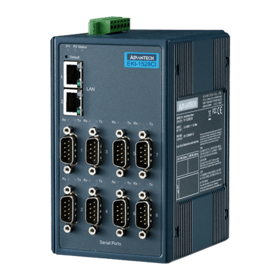
Hardware Overview 2.1.1 Front View The following view applies to EKI-1528I and EKI-1528CI. P1 P2 Status EKI-1528I Default Serial Ports Figure 2.1 Front View No. Item Description System LED panel See “LED Indicators” on page 7 for further details. Default button Press at least 10secs to reset device to default settings. -
Page 16: Rear View
2.1.2 Rear View Figure 2.2 Rear View No. Item Description Wall mounting holes Screw holes (x6) used in the installation of a wall mounting plate DIN-Rail mounting Mounting plate used for the installation to a standard DIN rail plate 2.1.3 Top View Figure 2.3 Top View No. -
Page 17: Led Indicators
2.1.4 LED Indicators 1 2 3 P1 P2 Status EKI-1528I Default Figure 2.4 System LED Panel No. LED Name LED Color Description Green Power 1 is on Power 1 is off, or power error condition exists Green Power 2 is on... -
Page 18: Dimensions
2.1.5 Dimensions 86.00 83.50 50.67 86.60 Figure 2.5 Dimensions Connecting Hardware 2.2.1 Choosing a Location 2.2.1.1 DIN Rail Mounting The DIN rail mount option is the quickest installation option. Additionally, it optimizes the use of rail space. The metal DIN rail kit is secured to the rear of the serial device server. The device can be mounted onto a standard 48.5mm (1.91”) x 66mm (2.6”) height DIN rail. -
Page 19: Figure 2.6 Installing The Din-Rail Mounting Kit
devices can be mounted vertically or horizontally. Refer to the following guidelines for further information. Note! A corrosion-free mounting rail is advisable. When installing, make sure to allow for enough space to properly install the cabling. Installing the DIN-Rail Mounting Kit Insert the top back of the mounting bracket over the DIN rail. -
Page 20: Figure 2.7 Removing The Din-Rail
Once the bottom is clear of the DIN rail, lift the device straight up to unhook it from the DIN rail. DIN Rail Figure 2.7 Removing the DIN-Rail 2.2.1.2 Wall-Mounting The wall mounting option provides better shock and vibration resistance than the DIN rail vertical mount. -
Page 21: Figure 2.8 Installing Wall Mount Plates
Secure the wall mount plates with M3 screws, see the following figure. Figure 2.8 Installing Wall Mount Plates Once the wall mounting plates are secure on the device, you will need to attach the wall screws (x6). Locate the installation site and place the server against the wall, making sure it is the final installation location. -
Page 22: Serial Connection
Align the wall mount plate over the screws on the wall. Install the wall mount plate on the screws and slide it forward to lock in place, see the following figure. Figure 2.10 Wall Mount Installation Once the device is installed on the wall, tighten the screws to secure the device. 2.2.2 Serial Connection EKI-1528 Series provides eight ports DB9 (male) connectors. -
Page 23: Power Connection
2.2.3 Power Connection 2.2.3.1 Overview Warning! Power down and disconnect the power cord before servicing or wiring the serial device server. Caution! Do not disconnect modules or cabling unless the power is first switched off. The device only supports the voltage outlined in the type plate. Do not use any other power components except those specifically designated for the serial device server. -
Page 24: Installing The Configuration Utility
Microsoft .NET Framework version 2.0 or greater is required for this application. Insert the Advantech EKI Device Configuration Utility CD-ROM into the CD- ROM drive (whereas E:\ is the drive name of your CD-ROM) on the host PC. Use Windows explorer or the Windows Run command to execute the setup pro- gram, the path for the setup program on the CD-ROM is as follows: E:\EKI_Device_Configuration_Utility_v2.01.exe... -
Page 25: Figure 2.14 Installshield Wizard 2 Of 4
The Software License Agreement displays, press I Agree to continue or Cancel to stop the installation. Figure 2.14 InstallShield Wizard 2 of 4 The InstallShield continues and a status screen displays. The default installation path is C:\Program Files\EKI Device Configuration Utility. Figure 2.15 InstallShield Wizard 3 of 4 EKI-1528-DR Series User Manual... -
Page 26: Figure 2.16 Installshield Wizard 4 Of 4
Once the installation of the package is finished a Configuration Utility Setup screen displays. Click Finish to conclude the process and exit the InstallShield Wizard. Figure 2.16 InstallShield Wizard 4 of 4 EKI-1528-DR Series User Manual... -
Page 27: Chapter 3 Utility Configuration
Chapter Utility Configuration... -
Page 28: Configuration Utility Overview
PC. With this secure function enabled, other PCs will not have permission for configuration. After the installation program on the Advantech EKI Series Driver Utility CD-ROM is fin- ished, the serial device servers are ready for use and configuration. -
Page 29: Quick Tool Bar
EKI-1000, ADAM-4570, and EDG-4500 serial device servers. Quick Tool Bar The Advantech EKI Device Configuration Utility makes use of a Quick Tool Bar menu to allow quick access to the management functions. See the following figure for fur- ther information. -
Page 30: Utility Settings
Icon Item Description Add IP Address to Click to include the selected IP Address into the Favor- Favorite ites list group. Search for a Range Click to begin a range search. Enter the beginning and of IP Addresses ending IP addressed to being a search within the string parameters. -
Page 31: Figure 3.4 View > Settings > Device Manager
Item Description Apply Click Apply to save the main form settings. Device Manager Figure 3.4 View > Settings > Device Manager Item Description Device Manager Tree View Grouping Click the drop-down menu to enable or disable grouping. Show Empty Device Type Check the check box to show empty device type node or not. -
Page 32: Discovering Your Device Server
3.3.2.1 Auto Searching Advantech EKI Serial Device Server Configuration Utility 2.01 or higher will automati- cally search all the EKI-15xx(-DR) series serial device servers on the network and show them on the Serial Device Server List Area of the utility. The utility provides an auto-search function to show your device (s) by simply executing the configuration utility program from the Start Menu. -
Page 33: Figure 3.6 Selecting A Group
Information”, and “Serial Port Information”. In the serial port information frame, it dis- plays the operation mode, status and connected host IP. Figure 3.6 Selecting a Group Click on the “+” before the device name, and the utility will expand the interfaces on this device server. -
Page 34: Network Settings
Click on each item to enter the configuration page to change the setting. The configu- ration will be introduced on following sections. Figure 3.8 Viewing Basic Settings 3.3.3 Network Settings Prior to setting up the server’s IP address determine the IP address mode. There are four mode types available: ... -
Page 35: Figure 3.9 Network Settings Overview
You can choose from four possible IP Configuration modes --- Static, DHCP, BOOTP, and DHCP/BOOTP. Figure 3.9 Network Settings Overview Item Description Static IP Static IPUser defined IP address, Subnet Mask, and Default Gateway. DHCP + Auto-IP DHCP Server assigned IP address, Subnet Mask, Default Gate- way, and DNS. -
Page 36: Administrator Settings
Select Reset Device. Figure 3.10 Reset Device Administrator Settings 3.4.1 Locate the Serial Device Server When several serial device servers are connected to the network, identification of a specific serial device is possible through the Locate function. To locate the serial device server: From the device list frame, locate the desired device and right-click on it to dis- play the settings menu. -
Page 37: Lock/Unlock The Serial Device Server (Password Protection)
Select Locate from the menu. Figure 3.11 Locate the Serial Device Server The unit’s Status LED will turn solid amber and the buzzer will make a beep sound until you click Stop Locate. 3.4.2 Lock/Unlock the Serial Device Server (Password Protection) The configuration utility provides the "Lock Device"... -
Page 38: Figure 3.12 Lock The Serial Device Server
Select Lock Device. Figure 3.12 Lock the Serial Device Server Enter a password and re-confirm the profile password. Figure 3.13 Enter a Password After re-confirming the password, the serial device server will reboot automati- cally and store your password in the memory. EKI-1528-DR Series User Manual... -
Page 39: Change Password
3.4.2.2 Unlock the Serial Device Server If you want to disable this function or change the password, click "Change Password" to change the password to default "None" (leave the new password and confirm new password columns blank). The serial device server will restart and store the new password in the memory. -
Page 40: Restore To Factory Default Settings
3.4.4 Restore to Factory Default Settings The configuration utility provides this function to restore the serial device server to factory default settings. The confirm message will display when you click Restore to Factory Default Settings. If you really want to restore the serial device sever to fac- tory default settings, click “Yes”... -
Page 41: Add To Favorite
See “Manual Mapping” on page 43 for further details. 3.4.9 Update Firmware Advantech continually upgrades its firmware to keep up with the ever-expending world of computing. You can use the update firmware function in the utility to carry out the upgrade procedure. Please access Advantech’s website: http://www.advan- tech.com to download the latest version of the firmware. - Page 42 Wait for few seconds to process the updating firmware. After downloading the firm- ware completely, click on the OK button. The serial device server will restart automat- ically. Note! Be sure that the host PC Ethernet network domain is as same as the EKI-1528 Series serial device server or the host PC can establish the TCP connection with the serial device server while doing the updating firmware process.
-
Page 43: Selecting An Operating Mode
Chapter Selecting an Operating Mode... -
Page 44: Overview
PC. The Advantech redirector can create up to 255 virtual COM ports. Application on the host can open virtual COM port to access the serial device servers at the same time. -
Page 45: Normal Mode
this configuration is configured differently, the data communication will not function correctly. Figure 4.2 Configuring Virtual COM Mode The Host Idle Timeout setting monitors the connection between the host and the device. If the Host Idle Timeout setting time is reached, the device server will release the resources allocated to the port mapping. -
Page 46: Usdg Data Mode
IP address and TCP port number of the network hosts connected to the EKI serial device server using the Advantech Serial Device Server Configuration Utility. After configuring the devices, when the EKI serial device server receives the data from the serial port, and the device server connects to the hosts which are configured. -
Page 47: Usdg Data Tcp Server Mode
In the Peer for Receiving Data menu, entering “0” as the value for the Local Port will assign a random TCP Port for an EKI device. Figure 4.4 Peer for Receiving Data 4.3.2 USDG Data TCP Server Mode In TCP server mode, the TCP connection is initiated from the host to the EKI serial device server. -
Page 48: Usdg Data Udp Client/Server Mode
4.3.3 USDG Data UDP Client/Server Mode The USDG UDP mode is primarily used for the broadcasting of messages over a net- work. In UDP server mode, data is transmitted from the Host connected tothe EKI- 1528 Series USDG UDP Port (Default Port 5300). In the default UDP client mode, EKI serial device servers simultaneously transmits UDP messages to a maximum of 16 peers. -
Page 49: Hangup Character
If you want a serial device running application program to connect/disconnect to dif- ferent devices on request, this function is available through the USDG Control mode. Figure 4.7 USDG Control Mode Please refer to the USDG TCP/UDP server operating mode to setup the Data Listen Port, Command Listen Port, and Data Idle Timeout. -
Page 50: Rfc2217 Mode
Command Function <LF><CR> ERROR <LF><CR> Incorrect commands <LF><CR> FAIL <LF><CR> If you issue an ATDT command and can not connect to the device, it will response “FAIL”. RFC2217 Mode RFC2217 mode is similar to virtual COM mode in that a driver is used to establish a transparent connection between a host computer and a serial device by mapping the serial port on EKI-1528 Series devices to a local COM port on a host computer. -
Page 51: Setting Up Com Port Redirector
Chapter Setting Up COM Port Redirector... -
Page 52: Setting Com Redirector
Setting COM Redirector Advantech COM port mapping software is a serial COM port redirector that creates virtual COM ports and provides access to serial devices connected to an Advantech serial device servers. Your serial device applications can communicate with serial devices connected to the Advantech serial device servers without software changes. -
Page 53: Manual Mapping
Manual Mapping On your desktop, navigate to Start > All Programs > EKI Device Configura- tion Utility and click Advantech EKI Device Configuration Utilityto open the utility. Under Serial Device Servers, locate your server and click the icon to expand the listing. -
Page 54: Figure 5.5 Selecting Manual Mapping
Locate Manual Mapping and select it. Figure 5.5 Selecting Manual Mapping The Manual Mapping Virtual COM Port window displays. In the Device > Serial Port drop-down menu, select the target port to map. This is the physical serial port on the EKI device. In the Host >... -
Page 55: Configuration Wizard
Configuration Wizard On your desktop, navigate to Start > All Programs > EKI Device Configura- tion Utility and click Advantech EKI Device Configuration Utilityto open the utility. Under Serial Device Servers, locate your server and click the icon to expand the listing. -
Page 56: Confirming Virtual Com Settings
Confirming Virtual COM Settings On your desktop, navigate to Start > All Programs > EKI Device Configura- tion Utility and click Advantech EKI Device Configuration Utilityto open the utility. Locate Serial Ports menu in the menu pane and click on the Expand icon next to Virtual COM Ports to view a list of the mapped ports. -
Page 57: Figure 5.10 System Port Vcom Mapping Configuration
The newly mapped VCOM port should be listed under the same mapped settings used in the previous steps. Figure 5.10 System Port VCOM Mapping Configuration The newly mapped VCOM port is listed under the same mapped settings used in the previous steps. -
Page 58: Removing Vcom Ports
Removing VCOM Ports On your desktop, navigate to Start > All Programs > EKI Device Configura- tion Utility and click Advantech EKI Device Configuration Utilityto open the utility. Under Serial Ports, click the expand icon on Virtual COM Ports to view the con- figured port list. -
Page 59: Running A Diagnostic Test
After upgrading to Utility 2.01, import your *.cpm file and restore your own Virtual COM Ports. Note! This Virtual COM Port Mapping tool can only recover Virtual COM Ports that have been mapped previously. For newly installed serial device servers, please follow the virtual COM Port mapping steps. Figure 5.13 Importing/Exporting Virtual COM Port Mapping Running a Diagnostic Test The purpose of this test is to ensure the communication from the host PC to the EKI-... -
Page 60: Figure 5.14 Running A Diagnostic Test
Click Simple Serial Test in the Tools menu. Figure 5.14 Running a Diagnostic Test EKI-1528-DR Series User Manual... -
Page 61: Chapter 6 Web Configuration
Chapter Web Configuration... -
Page 62: Overview
Overview EKI-1528 Series serial device server can be configured through a web interface. By using a standard web browser, the same procedure as with the Windows configura- tion utility can be used. In the browser’s address field, enter the IP Address of your EKI-1528 Series serial device server. -
Page 63: Accessing The Web Page Via Web Browser
6.2.2 Accessing the Web Page via Web Browser Once the device is installed and connected, power on the device. The following infor- mation guides you through the logging in process. Launch your web browser on the PC. In the browser’s address bar, type the device’s default IP address (10.0.0.1 (Eth1) and 10.0.0.2 (Eth2)). -
Page 64: Ethernet Configuration
Ethernet Configuration Choose either Eth 1 or Eth 2 in the Ethernet Configuration page.Enter the corre- sponding values for your network environment. Remember press Save after fill in all values. To access this page, click Ethernet Configuration. Figure 6.3 Ethernet Configuration The following table describes the items in the previous figure. -
Page 65: Port Configuration
Note! All new configurations will take effect after rebooting. To reboot the device, click Tools > Reboot. Port Configuration There are Basic, Operation Mode, and Advanced Setting in the serial port configura- tion. For more detailed information for setting. 6.5.1 Basic The Basic menu allows for the configuration of the serial interface type, baud rate, parity, data / stop bits, and flow control for port configuration. -
Page 66: Figure 6.5 Port Configuration > Operation
To access this page, click Port Configuration > Operation. Figure 6.5 Port Configuration > Operation The following table describes the items in the previous figure. Item Description Mode Click the drop-down menu to select the port configuration mode: Vir- tual COM Mode, USDG Data Mode, USDG Control Mode or RFC2217 Mode. -
Page 67: Advanced
Item Description Protocol Click the drop-down menu to select the protocol: TCP or UDP. Data Idle Timeout Enter a value to define the data idle timeout period. Data Listen Port Enter a value to identify the channel for remote initiating connections. Command Listen Enter a value to identify the command listen port for accepting con- Port... -
Page 68: Figure 6.6 Port Configuration > Advanced
To access this page, click Port Configuration > Advanced. Figure 6.6 Port Configuration > Advanced The following table describes the items in the previous figure. Item Description Enable Delay Time Click the option to enter the value to postpone the receive data. Ignore Purge Click the option to purge the serial port when the serial port opens first time. -
Page 69: Monitor
Item Description Transmitter Trigger Level Click the option to designate to suspend or resume transmission. Flow Control Lower Trigger Levels Click to set register for automatic flow control. FCL stores the lower trigger level. Flow Control Higher Trigger Level Click to set register for automatic flow control. FCH stores the upper trigger level. -
Page 70: Statistic
The following table describes the items in the previous figure. Item Description Operation Mode Display the current operation mode of the selected port. Baud Rate Display the current baud rate of the selected port. Data Bits Display the current data bits of the selected port. Stop Bits Display the current stop bits of the selected port. -
Page 71: Connected Ip
6.6.3 Connected IP The Monitor Connected IP page allows for easy viewing of all connected device’s IP address. To access this page, click Monitor > Connected IP. Figure 6.9 Monitor > Connected IP The displayed attributes are not configurable in this menu, and are for information purposes only. -
Page 72: Setting
6.7.1 Setting To access this page, click Alarm > Setting. Figure 6.10 Alarm > Setting The following table describes the items in the previous figure. Item Description Mail Server Mail Server This field is for your mail server’s domain name or IP address. From Email address This is the e-mail address from which automatic e-mail warnings will be sent. -
Page 73: Event
Item Description Contact Identify the system contact of your agent. Location Identify the system location of your agent. Save Click Save to save the values and update the screen. 6.7.2 Event In this page, you can configure events which will trigger logging or notification. You can select three methods (Mail, SNMP, or log file) to record or send event mesages. -
Page 74: Figure 6.11 Alarm > Event (1 Of 2)
To access this page, click Alarm > Event. Figure 6.11 Alarm > Event (1 of 2) The following table describes the items in the previous figure. Item Description System Event Cold Start Click the option to select a warning type when the device server’s power is cut off and reconnected. -
Page 75: Syslogd
Item Description Warm Start Click the option to select a warning type when the device server is reboot. Authentication fail- Click the option to select a warning type when an incorrect password is entered. IP address changed Click the option to select a warning type when the IP address is changed. -
Page 76: Syslogd Message
6.8.2 Syslogd Message After enabling the syslogd function, users can check the history in the syslogd mes- sage page. To access this page, click Syslogd > Syslogd Message. Figure 6.13 Syslogd > Syslogd Message Tools The EKI serial device server provides tools for access to ping and reset functions. 6.9.1 Ping The ping page can help users diagnose ethernet problems. -
Page 77: Reboot
To access this page, click Tools > Ping. Figure 6.14 Tools > Ping The following table describes the items in the previous figure. Item Description Enter the IP address or host name of the station to ping. The initial value is blank. The IP Address or host name you enter is not retained across a power cycle. -
Page 78: Management
6.10 Management The EKI serial device server allows for easy installation and maintenance and reli- able maintenance access from anywhere. With the reliable management tools avail- able, you can streamline staffing and troubleshooting requirements to a centralized system. 6.10.1 Log File If users enable the system event or serial event to log in file, users can download the log file from here. -
Page 79: Secure Access Ip
If you have set a password through the configuration utility or Telnet or serial console, when you access the web configuration, you need to key in the password. It is not necessary to enter the user name in the dialog. If you want to disable the password protection, change the password to default option None (leave the new password column blank). - Page 80 Chapter Telnet/Serial Console Configuration...
-
Page 81: Overview
Overview The purpose of the Console Configuration is to help you manage your device in con- sole mode. One of the main functions of the console mode is to change the web con- figuration login password. You can use terminal software like Hyper Terminal, Telix and other related terminal software. -
Page 82: Figure 7.3 Telnet Connection Console
After connecting to the serial device server in HyperTerminal console, a welcome greeting displays. Figure 7.3 Telnet Connection Console At the command prompt, you can type a “help” followed by the Enter button, or <Tab> twice, to display the command list. You can toggle between the different command menu options. - Page 83 Usage: system name [Maximum length 31 bytes] Set current device name. Usage: system desc [Maximum length 127 bytes] Set current device description. port Usage: port [nn|all] Show port status and informations. Usage: port [nn] desc [Maximum length 127 bytes] Set serial port description. Usage: port [nn|all] type [232|422|485] flow [] flow 0:None.
- Page 84 value 1 :Setting power on. value 2 :Setting accept on. value 4 :Setting transmission on. Usage: portadv [nn|all] dtr [] Set port DTR status. value 0 :None Setting. value 1 :Setting power on. value 2 :Setting accept on. value 4 :Setting transmission on. mvcom Usage: mvcom Show all port mode and mode informations.
- Page 85 Usage: mdata [nn|all] autopeerip [ON|OFF] Set auto connect to peer ip as on or off. Usage: mdata [nn|all] peernum [1-16] peer [d.d.d.d:d] ... Set peer IP address and port for receive data. Usage: net [1|2] Show device network status and informations. Usage: net [1|2] mode [static|dhcp|bootp|all] Set network operating mode.
- Page 86 Usage: monitor port [1|2|..] statistic Monitor COM port statistic data Usage: monitor port [1|2|..] ip Monitor connected IP time Usage: time Show current time informations. Usage: time [YYYYMMDDhhmmss] Set current time configuration. Usage: time ntp [timeserver] Set current time server configuration. service Usage: service telnet [enable|disable] Enable/Disable telnet function...
- Page 87 Appendix TCP and UDP Port Numbers...
-
Page 88: List Of Known Tcp And Udp Port Numbers
List of Known TCP and UDP Port Numbers Port Protocol Service 5048 (TCP/UDP) Configuration Utility 5058 (TCP/UDP) Configuration Utility 5202 (TCP) VCOM/RVCOM 9999 (TCP) Firmware Download (TCP) (TCP) Telnet (TCP) SMTP (Mail Client) (TCP/UDP) (UDP) BOOTP Server/DHCP (UDP) BOOTP Client/DHCP (TCP) Web Interface/HTTP (TCP) - Page 89 No part of this publication may be reproduced in any form or by any means, electronic, photocopying, recording or otherwise, without prior written permis- sion of the publisher. All brand and product names are trademarks or registered trademarks of their respective companies. © Advantech Co., Ltd. 2016...
Need help?
Do you have a question about the EKI-1528I and is the answer not in the manual?
Questions and answers