Sign In
Upload
Manuals
Brands
MR Manuals
Controller
tapcon 230 pro
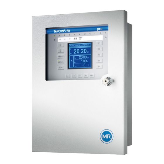
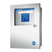
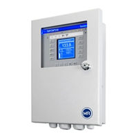
User Manuals: MR tapcon 230 pro Voltage Regulator
Manuals and User Guides for MR tapcon 230 pro Voltage Regulator. We have
2
MR tapcon 230 pro Voltage Regulator manuals available for free PDF download: Operating Instructions Manual
MR tapcon 230 pro Operating Instructions Manual (148 pages)
voltage regulator
Brand:
MR
| Category:
Controller
| Size: 8 MB
Table of Contents
Table of Contents
3
1 Introduction
8
Manufacturer
8
Subject to Change Without Notice
8
Completeness
8
Safekeeping
8
Notation Conventions
8
Hazard Communication System
9
Information System
10
Instruction System
10
Typographic Conventions
11
2 Safety
12
General Safety Information
12
Appropriate Use
12
Inappropriate Use
12
Personnel Qualification
13
Operator's Duty of Care
13
3 Product Description
14
Scope of Delivery
14
Function Description of the Voltage Regulation
15
Performance Features
16
Operating Modes
17
Hardware
19
Name Plate
20
Operating Controls
20
Display Elements
22
Serial Interface
24
Modules
24
4 Packaging, Transport and Storage
27
Packaging
27
Purpose
27
Suitability, Structure and Production
27
Markings
27
Transportation, Receipt and Handling of Shipments
27
Storage of Shipments
28
5 Mounting
30
Preparation
30
Mounting Device
30
Flush Panel Mounting
32
Wall Mounting with Mounting Brackets
33
Cap Rail Mounting
34
Wall Mounting
35
Removing the Door
36
Connecting Device
37
Cable Recommendation
38
Information about Laying Fiber-Optic Cable
38
Electromagnetic Compatibility
39
Connecting Cables to the System Periphery
44
Supplying the Voltage Regulator Using Auxiliary Voltage
44
Wiring Device
45
Checking Functional Reliability
45
6 Commissioning
47
Setting the Display Contrast
47
Setting Parameters
47
Setting the Language
48
Setting Further Parameters
48
Function Tests
49
Checking Control Functions
50
Checking Additional Functions
51
Checking Parallel Operation
54
7 Functions and Settings
59
Key Lock
59
General
59
Setting Device ID
59
Setting the Baud Rate
60
Setting the Switching Pulse Time
60
Setting Operations Counter
62
Dimming Display
63
Activating/Deactivating the Automatic Key Lock
63
Function Monitoring" Message for Monitoring Messages <30 V
64
Setting Motor Runtime Monitoring
65
Activate Manual Mode/Auto Mode
67
Activating Local/Remote
67
Normset
68
Control Parameters
70
Setting Desired Value 1
72
Selecting a Desired Value
73
Bandwidth
73
Setting Delay Time T1
75
Setting Control Response T1
76
Setting Delay Time T2
76
Limit Values
77
Setting Undervoltage Monitoring U
78
Setting Overvoltage Monitoring U
80
Setting Overcurrent Monitoring I
82
Set Undercurrent Monitoring I
83
Activate/Deactivate Active Power Monitoring
84
Permitted Tap Positions
84
Compensation
86
Line Drop Compensation
86
Z Compensation
89
Transformer Data
91
Setting the Primary Transformer Voltage
92
Setting the Secondary Transformer Voltage
93
Setting Primary Transformer Current
93
Setting the Current Transformer Connection
94
Setting the Phase Difference for the Current Transformer/Voltage Transformer
94
Parallel Operation
98
Assigning CAN Bus Address
98
Selecting Parallel Operation Method
99
Assigning a Parallel Operation Group
103
Activating/Deactivating Blocking in Simplex Mode
104
Setting Delay Time for Parallel Operation Error Messages
104
Configuring the Maximum Permitted Tap Difference
104
Activating/Deactivating Follower Tapping Without Measured Voltage
105
Activating/Deactivating Parallel Operation
105
Tap Position Capture
106
Digital Tap Position Capture
106
Analog Tap Position Capture
107
Setting the Desired Voltage Level Remotely
109
Activate/Deactivate Setting the Desired Voltage Level Remotely
110
Setting Lower Limit Value for the Desired Value
110
Setting Upper Limit Value for the Desired Value
111
Configurable Inputs and Outputs
112
Linking Inputs with Functions
112
Linking Outputs with Functions
114
LED Selection
116
Information about Device
118
Displaying Info Screen
118
Displaying Measured Values
119
Display Calculated Values
120
Carrying out LED Test
120
Displaying Status of the MIO Card
121
Displaying Status of the PIO Card
122
Displaying Parallel Operation
122
Displaying Data on CAN Bus
123
Peak Memory
123
Resetting Parameters
124
Displaying Memory Overview
125
Displaying Event Overview
125
8 Fault Elimination
126
No Regulation in AUTO Mode
126
Unexplained Tap Change
126
Man-Machine Interface
127
Incorrect Measured Values
127
Parallel Operation Faults
128
Tap Position Capture Incorrect
128
Customized Gpis/Gpos
129
General Faults
129
Other Faults
130
9 Messages
131
10 Disposal
134
TAPCON® 230 Pro 3550953/00 en Maschinenfabrik Reinhausen
134
11 Overview of Parameters
135
12 Technical Data
139
Display Elements
139
Electrical Data
139
Dimensions and Weight
139
Ambient Conditions
141
Electrical Safety
141
Electromagnetic Compatibility
141
Environmental Durability Tests
142
Mechanical Stability
142
Glossary
143
List of Key Words
144
Advertisement
MR tapcon 230 pro Operating Instructions Manual (166 pages)
Voltage regulator
Brand:
MR
| Category:
Controller
| Size: 5 MB
Table of Contents
Table of Contents
3
1 Introduction
7
Manufacturer
7
Completeness
7
Safekeeping
7
Notation Conventions
7
Hazard Communication System
7
Information System
9
Instruction System
9
Typographic Conventions
10
2 Safety
11
Appropriate Use
11
Inappropriate Use
12
Fundamental Safety Instructions
12
Personnel Qualification
14
Personal Protective Equipment
15
3 Security
16
General
16
Operation
16
Commissioning
16
Communication Interfaces
17
Encryption Standards
17
4 Product Description
19
Scope of Delivery
19
Function Description of the Voltage Regulation
19
Performance Features
20
Operating Modes
21
Design
22
Display, Operating Elements and Front Interface
22
Leds
23
Connections and Fuses
24
Nameplate
25
Safety Markings
26
Connection Diagram and Grounding Screw
26
Visualization
27
5 Packaging, Transport and Storage
33
Suitability, Structure and Production
33
Markings
33
Transportation, Receipt and Handling of Shipments
33
Storage of Shipments
34
6 Mounting
35
Preparation
35
Minimum Distances
36
Assembly Variants
36
Flush Panel Mounting
36
Wall Mounting with Housing (Optional)
38
Connecting Device
40
Cable Recommendation
40
Electromagnetic Compatibility
41
Connecting Cables to the System Periphery
44
Connecting the CAN Bus
44
Connecting SCADA
47
Wiring Voltage Measurement/Current Measurement UI
51
Wiring Analog Inputs AI
52
Wiring Digital Inputs DI
53
Wiring Digital Outputs DO
54
Wiring Resistor Contact Series
54
Connecting the Power Supply
54
Performing Tests
56
7 Initial Steps
57
Establishing Connection to Visualization
57
8 Commissioning
60
Commissioning Wizard
60
Function Tests
60
Checking Measured Values and Status of Digital Inputs and Outputs
61
Testing the Device Control Function
61
Checking Parallel Operation
62
9 Operation
67
System
67
General
67
Configuring the Network
69
Setting the Device Time
70
Setting the Screensaver
71
Configuring Syslog
72
Scada
74
Linking Signals and Events
80
Configuring Analog Inputs
83
Configuring Digital Inputs and Outputs
85
Event Management
87
User Administration
88
Hardware
92
Software
92
Import/Export Manager
92
Power Grid
95
Transformer Data
95
Voltage Monitoring
100
Current Monitoring
102
Power Monitoring
104
Power Flow Monitoring
106
TAPCON® 2Xx Retrofit
107
On-Load Tap-Changer Regulator
109
Voltage Regulation
109
Line Drop Compensation
118
Parallel Operation
121
U Bandwidth Monitoring
130
On-Load Tap-Changer
132
Tap Position Monitoring
132
Tap Position Capture Method
133
Target-Tap-Position Operation
135
Information about the On-Load Tap-Changer
135
Motor-Drive Unit and Control Cabinet
136
Control of the Motor-Drive Unit
136
10 Maintenance and Care
140
11 Fault Elimination
141
General Faults
141
No Regulation in AUTO Mode
141
Unwanted On-Load Tap-Change Operation
142
Human-Machine Interface
142
Incorrect Measured Values
142
Parallel Operation Faults
143
Tap Position Capture Incorrect
144
Other Faults
145
12 Disposal
146
13 Technical Data
147
Display Elements
147
Materials
147
Dimensions
147
Power Supply
147
Voltage Measurement and Current Measurement
148
Central Processing Unit
149
Digital Inputs
151
Digital Outputs
152
Analog Inputs
154
Communication Interfaces
156
Tap Position Capture / Resistor Contact Series
158
Ambient Conditions
158
Standards and Directives
158
Connection Diagrams
160
TAPCON® 230 Expert
161
Glossary
164
Advertisement
Related Products
MR TAPCON 230
MR TAPCON 230 basic
MR TAPCON 230 AVT
MR TAPCON 230 VC
MR tapcon 240
MR TAPCON 260
MR TAPCON 250
MR TAPCON
MR TAPCON 230 Expert
MR TAPCON LV
MR Categories
Industrial Equipment
Controller
Measuring Instruments
Thermometer
Control Systems
More MR Manuals
Login
Sign In
OR
Sign in with Facebook
Sign in with Google
Upload manual
Upload from disk
Upload from URL