Table of Contents
Advertisement
Quick Links
DIN A4: 7.10028.31.00
©
KROHNE 03/2003
US size: 7.10028.71.00
GR
How to use these Instructions
The flowmeters are supplied ready for operation.
The primary head must be installed in the pipeline as described in the installation
instructions inside the packing of the primary head.
–
Storage and transport
–
Installation in the pipeline
–
Grounding
Installation instructions
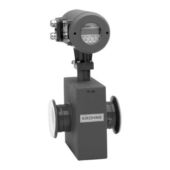
ALTOFLUX M900
ALTOFLUX 3080 K
Electromanetic flowmeters
for particulary applications
● Primary head
● Compact flowmeters
Pages 3+4
Pages 4-5/7-8
Page 9
Variable area flowmeters
Vortex flowmeters
Flow controllers
Electromagnetic flowmeters
Ultrasonic flowmeters
Mass flowmeters
Level measuring instruments
Communications technology
Engineering systems & solutions
Switches, counters, displays and recorders
Heat metering
Pressure and temperature
Advertisement
Table of Contents

Related Manuals for KROHNE ALTOFLUX M900


Summary of Contents for KROHNE ALTOFLUX M900
- Page 1 DIN A4: 7.10028.31.00 © KROHNE 03/2003 US size: 7.10028.71.00 Installation instructions ALTOFLUX M900 ALTOFLUX 3080 K Electromanetic flowmeters for particulary applications ● Primary head ● Compact flowmeters Variable area flowmeters Vortex flowmeters Flow controllers Electromagnetic flowmeters Ultrasonic flowmeters How to use these Instructions...
-
Page 2: Table Of Contents
In addition, the ”General conditions of sale” forming the basis of the purchase contract are applicable. If ALTOFLUX flowmeters need to be returned to Krohne, please note the information given on the last-but-one page of this manual. Krohne regret that they cannot repair or check your flowmeter(s) unless accompanied by the completed form sheet. -
Page 3: Standards And Approvals
Do not lift flowmeter by the signal converter Do not set flowmeter down on signal converter housing or the terminal box. housing or terminal box. PLEASE NOTE the temperature limits for storage and transport, see Page 4. Installation and operating instruction ALTOFLUX M900 and 3080 K... -
Page 4: Important Information For Installation: Please Note
Strong electromagnetic fields, avoid in vicinity of flowmeter • Straight inlet run minimum of 5 × DN and outlet run minimum of 2 × DN, (DN = meter size), measured from the electrode axis. Installation and operating instruction ALTOFLUX M900 and 3080 K... -
Page 5: Suggestions For Installation
Pumps Open feed or discharge Never install flowmeter on pump suction side. Install meter in low section of pipe. open discharge Installation and operating instruction ALTOFLUX M900 and 3080 K... -
Page 6: Instrument Nameplate
M900 and 3080 K are approved as electrical equipment to the harmonized European Standards and to Factory Mutual (FM). Test certificate, certificate of conformity and wiring instructions for these devices are attached to the ”Ex” installation instructions, provided only with hazardous-duty equipment. Installation and operating instruction ALTOFLUX M900 and 3080 K... -
Page 7: Installation In The Pipeline
3 mm/0.12” thick 3 mm/0.12” thick Length: 30 mm/1.18”, for ≤ DN 300, ≤ 12“ 100 mm/3.94”, for ≥ DN 350, ≥ 14“ ® Teflon is a registered trademark of Du Pont. Installation and operating instruction ALTOFLUX M900 and 3080 K... -
Page 8: Torques
Note: Process pressure must not exceed ANSI 12 x M 20 (63.7) (54.9) flange rating. Refer to ANSI Standard B 16.5. 12 x M 24 (104.2) (75.9) ® Teflon is registered trademark of Du Pont Installation and operating instruction ALTOFLUX M900 and 3080 K... -
Page 9: Grounding
Cu (10 AWG), not included with flowmeter, to be provided by customer Protective conductor required if the ALTOFLUX M900 is operated with a signal converter that supplies a field current of > 125 mA / > 60 V. Wire ≥ 4 mm Cu (10 AWG), not included with flowmeter, to be provided by customer. -
Page 10: Replacement Of The Separate Primary Head
100% meter size will need to be reset. After resetting the signal converter, carry out a zero point check. If necessary, reset the internal electronic totalizer of the signal converter. Installation and operating instruction ALTOFLUX M900 and 3080 K... - Page 11 Notes Installation and operating instruction ALTOFLUX M900 and 3080 K...
-
Page 12: Technical Data
Technical data Installation and operating instruction ALTOFLUX M900 and 3080 K... - Page 13 Installation and operating instruction ALTOFLUX M900 and 3080 K...
-
Page 14: Dimensions And Weights
Dimensions and weights Installation and operating instruction ALTOFLUX M900 and 3080 K... - Page 15 Installation and operating instruction ALTOFLUX M900 and 3080 K...
- Page 16 Installation and operating instruction ALTOFLUX M900 and 3080 K...
-
Page 17: Limits
Limits Installation and operating instruction ALTOFLUX M900 and 3080 K... - Page 18 Notes Installation and operating instruction ALTOFLUX M900 and 3080 K...
-
Page 19: If You Need To Return Flowmeters For Testing Or Repair To Krohne
If you need to return flowmeters for testing or repair to KROHNE Your electromagnetic flowmeter accompanied by a certificate in line with the • following model confirming that the flowmeter is has been carefully manufactured and safe to handle. tested by a company with ISO 9001...
Need help?
Do you have a question about the ALTOFLUX M900 and is the answer not in the manual?
Questions and answers