Table of Contents
Advertisement
Quick Links
Title Page
GE Multilin
215 Anderson Avenue, Markham, Ontario
Canada L6E 1B3
Tel: (905) 294-6222 Fax: (905) 201-2098
Internet:
http://www.GEmultilin.com
*1601-0125-X1*
N60 Network Stability and
Synchrophasor Measurement System
UR Series Instruction Manual
Manual P/N: 1601-0125-X1 (GEK-113586)
IND.CONT. EQ.
N60 Revision: 6.0x
Copyright © 2011 GE Multilin
E83849
LISTED
52TL
GE Multilin
847710A1.CDR
I I SO9001:2000
GE Multilin's Quality Management
System is registered to
ISO9001:2000
QMI # 005094
UL # A3775
Advertisement
Table of Contents

Related Manuals for GE Multilin UR Series N60


Summary of Contents for GE Multilin UR Series N60
- Page 1 Title Page GE Multilin N60 Network Stability and Synchrophasor Measurement System UR Series Instruction Manual N60 Revision: 6.0x Manual P/N: 1601-0125-X1 (GEK-113586) Copyright © 2011 GE Multilin 847710A1.CDR E83849 I I SO9001:2000 GE Multilin LISTED 215 Anderson Avenue, Markham, Ontario IND.CONT.
- Page 3 Addendum GE Multilin ADDENDUM This addendum contains information that relates to the N60 Network Stability and Synchrophasor Measurement Sys- tem, version 6.0x. This addendum lists a number of information items that appear in the instruction manual GEK- 113586 (revision X1) but are not included in the current N60 operations.
-
Page 5: Table Of Contents
TYPICAL WIRING....................3-6 3.2.2 DIELECTRIC STRENGTH ................. 3-7 3.2.3 CONTROL POWER ................... 3-7 3.2.4 CT AND VT MODULES ..................3-8 3.2.5 PROCESS BUS MODULES ................3-10 3.2.6 CONTACT INPUTS AND OUTPUTS ............... 3-10 GE Multilin N60 Network Stability and Synchrophasor Measurement System... - Page 6 5.2.6 REAL TIME CLOCK ..................5-37 5.2.7 OSCILLOGRAPHY ...................5-38 5.2.8 DATA LOGGER ....................5-41 5.2.9 DEMAND ......................5-42 5.2.10 USER-PROGRAMMABLE LEDS ..............5-43 5.2.11 USER-PROGRAMMABLE SELF TESTS ............5-47 5.2.12 CONTROL PUSHBUTTONS ................5-47 5.2.13 USER-PROGRAMMABLE PUSHBUTTONS............5-49 N60 Network Stability and Synchrophasor Measurement System GE Multilin...
- Page 7 DIRECT ANALOG INPUTS AND OUTPUTS ..........5-192 5.8.12 DIRECT INTEGER INPUTS AND OUTPUTS ..........5-194 5.8.13 TELEPROTECTION INPUTS/OUTPUTS ............5-196 5.8.14 IEC 61850 GOOSE ANALOGS..............5-198 5.8.15 IEC 61850 GOOSE INTEGERS..............5-199 GE Multilin N60 Network Stability and Synchrophasor Measurement System...
- Page 8 BREAKER MAINTENANCE ................6-24 6.5 PRODUCT INFORMATION 6.5.1 MODEL INFORMATION ...................6-25 6.5.2 FIRMWARE REVISIONS..................6-25 7. COMMANDS AND 7.1 COMMANDS TARGETS 7.1.1 COMMANDS MENU ...................7-1 7.1.2 VIRTUAL INPUTS ....................7-1 7.1.3 CLEAR RECORDS .....................7-2 viii N60 Network Stability and Synchrophasor Measurement System GE Multilin...
- Page 9 B.2.6 EXCEPTION RESPONSES ................B-5 B.3 FILE TRANSFERS B.3.1 OBTAINING RELAY FILES VIA MODBUS ............B-6 B.3.2 MODBUS PASSWORD OPERATION ...............B-7 B.4 MEMORY MAPPING B.4.1 MODBUS MEMORY MAP .................B-8 B.4.2 DATA FORMATS .....................B-65 GE Multilin N60 Network Stability and Synchrophasor Measurement System...
- Page 10 DNP V3.00 DEVICE PROFILE ................E-1 E.1.2 IMPLEMENTATION TABLE ................E-4 E.2 DNP POINT LISTS E.2.1 BINARY INPUT POINTS ................... E-8 E.2.2 BINARY AND CONTROL RELAY OUTPUT............E-9 E.2.3 COUNTERS..................... E-10 E.2.4 ANALOG INPUTS.................... E-11 N60 Network Stability and Synchrophasor Measurement System GE Multilin...
- Page 11 F.1 CHANGE NOTES F.1.1 REVISION HISTORY ..................F-1 F.1.2 CHANGES TO THE MANUAL ................F-1 F.2 ABBREVIATIONS F.2.1 STANDARD ABBREVIATIONS ............... F-10 F.3 WARRANTY F.3.1 GE MULTILIN WARRANTY ................F-12 INDEX GE Multilin N60 Network Stability and Synchrophasor Measurement System...
- Page 12 TABLE OF CONTENTS N60 Network Stability and Synchrophasor Measurement System GE Multilin...
-
Page 13: Getting Started
• GE EnerVista CD (includes the EnerVista UR Setup software and manuals in PDF format). • Mounting screws. For product information, instruction manual updates, and the latest software updates, please visit the GE Multilin website at http://www.GEmultilin.com. If there is any noticeable physical damage, or any of the contents listed are missing, please contact GE Multilin immediately. -
Page 14: Ur Overview
This new generation of equipment must also be easily incorporated into automation systems, at both the station and enterprise levels. The GE Multilin Universal Relay (UR) has been developed to meet these goals. N60 Network Stability and Synchrophasor Measurement System... -
Page 15: Hardware Architecture
(dual) ring configuration. This feature is optimized for speed and intended for pilot- aided schemes, distributed logic applications, or the extension of the input/output capabilities of a single relay chassis. GE Multilin N60 Network Stability and Synchrophasor Measurement System... -
Page 16: Software Architecture
5. An explanation of the use of inputs from CTs and VTs is in the Introduction to AC sources section in chapter 5. A description of how digital signals are used and routed within the relay is contained in the Introduction to FlexLogic™ section in chapter 5. N60 Network Stability and Synchrophasor Measurement System GE Multilin... -
Page 17: Enervista Ur Setup Software
In the EnerVista Launch Pad window, click the Add Product button and select the “N60 Network Stability and Syn- chrophasor Measurement System” from the Install Software window as shown below. Select the “Web” option to GE Multilin N60 Network Stability and Synchrophasor Measurement System... -
Page 18: Configuring The N60 For Software Access
EnerVista UR Setup software. The N60 can also be accessed locally with a laptop computer through the front panel RS232 port or the rear Ethernet port using the Quick Connect feature. N60 Network Stability and Synchrophasor Measurement System GE Multilin... - Page 19 RS232 port is intended for local use and is not described in this section; see the Using the Quick Connect Feature section for details on configuring the RS232 port. A GE Multilin F485 converter (or compatible RS232-to-RS485 converter) is will be required. Refer to the F485 instruction manual for additional details.
- Page 20 Enter the desired name in the “Device Name” field and a description (optional) of the site. Select “Ethernet” from the Interface drop-down list. This will display a number of interface parameters that must be entered for proper Ethernet functionality. Figure 1–5: CONFIGURING ETHERNET COMMUNICATIONS N60 Network Stability and Synchrophasor Measurement System GE Multilin...
-
Page 21: Using The Quick Connect Feature
Enter an IP address of “1.1.1.1” and select the ENTER key to save the value. In the same menu, select the setting. SUBNET IP MASK Enter a subnet IP address of “255.0.0.0” and press the ENTER key to save the value. GE Multilin N60 Network Stability and Synchrophasor Measurement System... - Page 22 Now, assign the laptop computer an IP address compatible with the relay’s IP address. From the Windows desktop, right-click the My Network Places icon and select Properties to open the network con- nections window. Right-click the Local Area Connection icon and select Properties. 1-10 N60 Network Stability and Synchrophasor Measurement System GE Multilin...
- Page 23 Minimum = 0ms, Maximum = 0ms, Average = 0 ms Note that the values for will vary depending on local network configuration. time If the following sequence of messages appears when entering the command: C:\WINNT>ping 1.1.1.1 GE Multilin N60 Network Stability and Synchrophasor Measurement System 1-11...
- Page 24 Default Gateway ..: C:\WINNT> It may be necessary to restart the laptop for the change in IP address to take effect (Windows 98 or NT). 1-12 N60 Network Stability and Synchrophasor Measurement System GE Multilin...
- Page 25 From the Windows desktop, right-click the My Network Places icon and select Properties to open the network con- nections window. Right-click the Local Area Connection icon and select the Properties item. Select the Internet Protocol (TCP/IP) item from the list provided and click the Properties button. GE Multilin N60 Network Stability and Synchrophasor Measurement System 1-13...
- Page 26 Device Setup menu, for the purpose of communicating to multiple relays. This feature allows the user to identify and interrogate, in seconds, all UR-series devices in a particular location. 1-14 N60 Network Stability and Synchrophasor Measurement System GE Multilin...
-
Page 27: Connecting To The N60 Relay
View the last recorded oscillography record. • View the status of all N60 inputs and outputs. • View all of the N60 metering values. • View the N60 protection summary. GE Multilin N60 Network Stability and Synchrophasor Measurement System 1-15... -
Page 28: Ur Hardware
Figure 1–7: RELAY COMMUNICATIONS OPTIONS To communicate through the N60 rear RS485 port from a PC RS232 port, the GE Multilin RS232/RS485 converter box is required. This device (catalog number F485) connects to the computer using a “straight-through” serial cable. A shielded twisted-pair (20, 22, or 24 AWG) connects the F485 converter to the N60 rear communications port. -
Page 29: Using The Relay
LED off. The relay in the “Not Programmed” state will block signaling of any output relay. These conditions will remain until the relay is explicitly put in the “Programmed” state. Select the menu message SETTINGS PRODUCT SETUP INSTALLATION RELAY SETTINGS RELAY SETTINGS: Not Programmed GE Multilin N60 Network Stability and Synchrophasor Measurement System 1-17... -
Page 30: Relay Passwords
NOTE 1.5.6 FLEXLOGIC™ CUSTOMIZATION FlexLogic™ equation editing is required for setting up user-defined logic for customizing the relay operations. See the Flex- Logic™ section in Chapter 5 for additional details. 1-18 N60 Network Stability and Synchrophasor Measurement System GE Multilin... -
Page 31: Commissioning
View the event recorder and oscillography or fault report for correct operation of inputs, outputs, and elements. If it is concluded that the relay or one of its modules is of concern, contact GE Multilin for prompt service. GE Multilin... - Page 32 1.5 USING THE RELAY 1 GETTING STARTED 1-20 N60 Network Stability and Synchrophasor Measurement System GE Multilin...
-
Page 33: Product Description
The N60 IEDs use flash memory technology which allows field upgrading as new features are added. The following Single Line Diagram illustrates the relay functionality using ANSI (American National Standards Institute) device numbers. GE Multilin N60 Network Stability and Synchrophasor Measurement System... - Page 34 VT fuse failure Event recorder Oscillography Same Functions as Breaker 1 TRIP CLOSE For Breaker 1 METERING Transducer Digitizer FlexElement Inputs Network Stability and Security Relay 847700A2.CDR Figure 2–1: SINGLE LINE DIAGRAM N60 Network Stability and Synchrophasor Measurement System GE Multilin...
-
Page 35: Ordering
Each of these modules can be supplied in a number of configurations specified at the time of ordering. The information required to completely specify the relay is provided in the following tables (see chapter 3 for full details of relay modules). Order codes are subject to change without notice. Refer to the GE Multilin ordering page at http://www.GEindustrial.com/multilin/order.htm for the latest details concerning N60 ordering options. -
Page 36: Replacement Modules
Not all replacement modules may be applicable to the N60 relay. Only the modules specified in the order codes are available as replacement modules. NOTE Replacement module codes are subject to change without notice. Refer to the GE Multilin ordering page at http:// www.GEindustrial.com/multilin/order.htm for the latest details concerning N60 ordering options. - Page 37 4 dcmA inputs, 4 dcmA outputs (only one 5A module is allowed) 8 RTD inputs INPUTS/OUTPUTS 4 RTD inputs, 4 dcmA outputs (only one 5D module is allowed) 4 dcmA inputs, 4 RTD inputs 8 dcmA inputs GE Multilin N60 Network Stability and Synchrophasor Measurement System...
-
Page 38: Specifications
30 ms at 1.10 pickup at 60 Hz Operate time: DV2, DV1 xor DV2, DV1 & DV2 Timing accuracy: ±3% or ±4 ms (whichever is greater) (L = Live, D = Dead) N60 Network Stability and Synchrophasor Measurement System GE Multilin... -
Page 39: User-Programmable Elements
Number: up to 256 logical variables grouped tual input under 16 Modbus addresses Reset mode: self-reset or latched Programmability: any logical variable, contact, or virtual input GE Multilin N60 Network Stability and Synchrophasor Measurement System... -
Page 40: Monitoring
01 channel for NN days 16 channels for NN days Triggers: any element pickup, dropout, or operate; digital input change of state; digital out- put change of state; self-test events Data storage: in non-volatile memory N60 Network Stability and Synchrophasor Measurement System GE Multilin... -
Page 41: Metering
3-Phase Power (P, Q, and S) present WATT-HOURS (POSITIVE AND NEGATIVE) and maximum measured currents Accuracy: ±2.0% of reading Accuracy: ±2.0% ±0 to 1 10 Range: Parameters: three-phase only Update rate: 50 ms GE Multilin N60 Network Stability and Synchrophasor Measurement System... -
Page 42: Inputs
Duration of auto-burnish impulse: 25 to 50 ms Remote devices: Default states on loss of comms.: On, Off, Latest/Off, Latest/On Ring configuration: Data rate: 64 or 128 kbps CRC: 32-bit 2-10 N60 Network Stability and Synchrophasor Measurement System GE Multilin... -
Page 43: Power Supply
95% voltage drop across the load impedance. Trickle current: approx. 1 to 2.5 mA Operate time: < 0.6 ms FORM-A CURRENT MONITOR Internal Limiting Resistor: 100 , 2 W Threshold current: approx. 80 to 100 mA GE Multilin N60 Network Stability and Synchrophasor Measurement System 2-11... - Page 44 Maximum voltage: 60 V DC Standard output points: 32 Internal fuse: 5 A / 350 V AC, Ceramic, Axial SLO User output points: BLO; Manufacturer: Conquer; Part number: SCD-A 005 2-12 N60 Network Stability and Synchrophasor Measurement System GE Multilin...
-
Page 45: Communications
MAXIMUM STANDARD FAST ETHERNET SEGMENT LENGTHS 10Base-T (CAT 3, 4, 5 UTP): 100 m (328 ft.) 100Base-TX (CAT 5 UTP):100 m (328 ft.) Shielded twisted pair: 150 m (492 ft.) GE Multilin N60 Network Stability and Synchrophasor Measurement System 2-13... -
Page 46: Inter-Relay Communications
– Overvoltage category: 20°C Ingress protection: IP20 front, IP10 back HUMIDITY Humidity: operating up to 95% (non-condensing) at 55°C (as per IEC60068-2-30 variant 1, 6days). 2-14 N60 Network Stability and Synchrophasor Measurement System GE Multilin... -
Page 47: Type Tests
IEEE/ANSI C37.90.1 2.5 kV, 1 MHz RF immunity IEEE/ANSI C37.90.2 20 V/m, 80 MHz to 1 GHz Safety UL508 e83849 NKCR Safety UL C22.2-14 e83849 NKCR7 Safety UL1053 e83849 NKCR GE Multilin N60 Network Stability and Synchrophasor Measurement System 2-15... -
Page 48: Production Tests
Units that are stored in a de-energized state should be powered up once per year, for one hour continuously, to NOTE avoid deterioration of electrolytic capacitors. 2-16 N60 Network Stability and Synchrophasor Measurement System GE Multilin... -
Page 49: Hardware
11.016” [279,81 mm] 9.687” [246,05 mm] 17.56” [446,02 mm] 7.460” [189,48 mm] 6.995” 6.960” [177,67 mm] [176,78 mm] 19.040” [483,62 mm] 842807A1.CDR Figure 3–1: N60 HORIZONTAL DIMENSIONS (ENHANCED PANEL) GE Multilin N60 Network Stability and Synchrophasor Measurement System... - Page 50 [466,60 mm] 0.280” [7,11 mm] Typ. x 4 CUT-OUT 4.000” [101,60 mm] 17.750” [450,85 mm] 842808A1.CDR Figure 3–2: N60 HORIZONTAL MOUNTING (ENHANCED PANEL) Figure 3–3: N60 HORIZONTAL MOUNTING AND DIMENSIONS (STANDARD PANEL) N60 Network Stability and Synchrophasor Measurement System GE Multilin...
-
Page 51: Module Withdrawal And Insertion
Before performing this action, control power must be removed from the relay. Record the original loca- tion of the module to ensure that the same or replacement module is inserted into the correct slot. Modules with current input provide automatic shorting of external CT circuits. GE Multilin N60 Network Stability and Synchrophasor Measurement System... -
Page 52: Rear Terminal Layout
Inst. Manual: Contact Outputs: Standard Pilot Duty / 250V AC 7.5A Serial Number: MAZB98000029 360V A Resistive / 125V DC Break Firmware: GE Multilin 4A @ L/R = 40mS / 300W 2004/03/20 Mfg. Date: Technical Support: Made in Tel: (905) 294-6222 http://www.GEIndustrial.com/Multilin... - Page 53 3 HARDWARE 3.1 DESCRIPTION Figure 3–7: EXAMPLE OF MODULES IN F AND H SLOTS GE Multilin N60 Network Stability and Synchrophasor Measurement System...
-
Page 54: Wiring
This diagram provides an example of how the device is wired, not specifically how to wire the device. Please refer to the Instruction Manual for additional details on wiring based on various configurations. Figure 3–8: TYPICAL WIRING DIAGRAM N60 Network Stability and Synchrophasor Measurement System GE Multilin... -
Page 55: Dielectric Strength
Each power supply has a green LED on the front of the module to indicate it is functional. The critical fail relay of the module will also indicate a faulted power supply. GE Multilin N60 Network Stability and Synchrophasor Measurement System... -
Page 56: Ct And Vt Modules
CT connections for both ABC and ACB phase rotations are identical as shown in the Typical wiring diagram. The exact placement of a zero-sequence core balance CT to detect ground fault current is shown below. Twisted-pair cabling on the zero-sequence CT is recommended. N60 Network Stability and Synchrophasor Measurement System GE Multilin... - Page 57 Current inputs Voltage inputs 8F, 8G, 8L, and 8M modules (4 CTs and 4 VTs) Current inputs 8H, 8J, 8N, and 8R modules (8 CTs) 842766A3.CDR Figure 3–11: CT/VT MODULE WIRING GE Multilin N60 Network Stability and Synchrophasor Measurement System...
-
Page 58: Process Bus Modules
3.2.5 PROCESS BUS MODULES The N60 can be ordered with a process bus interface module. This module is designed to interface with the GE Multilin HardFiber system, allowing bi-directional IEC 61850 fiber optic communications with up to eight HardFiber merging units, known as Bricks. - Page 59 Logic™ operand driving the contact output should be given a reset delay of 10 ms to prevent damage of NOTE the output contact (in situations when the element initiating the contact output is bouncing, at values in the region of the pickup value). GE Multilin N60 Network Stability and Synchrophasor Measurement System 3-11...
- Page 60 2 Inputs ~7a, ~7c 2 Inputs ~7a, ~7c 2 Inputs ~7a, ~7c 2 Inputs ~8a, ~8c 2 Inputs ~8a, ~8c 2 Inputs ~8a, ~8c 2 Inputs ~8a, ~8c 2 Inputs 3-12 N60 Network Stability and Synchrophasor Measurement System GE Multilin...
- Page 61 2 Inputs 2 Outputs Solid-State Solid-State ~6a, ~6c 2 Inputs 2 Outputs Not Used Not Used ~7a, ~7c 2 Inputs 2 Outputs Solid-State Solid-State ~8a, ~8c 2 Inputs Not Used GE Multilin N60 Network Stability and Synchrophasor Measurement System 3-13...
- Page 62 3.2 WIRING 3 HARDWARE 842762A2.CDR Figure 3–13: CONTACT INPUT AND OUTPUT MODULE WIRING (1 of 2) 3-14 N60 Network Stability and Synchrophasor Measurement System GE Multilin...
- Page 63 Figure 3–14: CONTACT INPUT AND OUTPUT MODULE WIRING (2 of 2) CORRECT POLARITY MUST BE OBSERVED FOR ALL CONTACT INPUT AND SOLID STATE OUTPUT CON- NECTIONS FOR PROPER FUNCTIONALITY. CAUTION GE Multilin N60 Network Stability and Synchrophasor Measurement System 3-15...
- Page 64 There is no provision in the relay to detect a DC ground fault on 48 V DC control power external output. We recommend using an external DC supply. NOTE 3-16 N60 Network Stability and Synchrophasor Measurement System GE Multilin...
- Page 65 = ON 842751A1.CDR Figure 3–17: AUTO-BURNISH DIP SWITCHES The auto-burnish circuitry has an internal fuse for safety purposes. During regular maintenance, the auto-burnish functionality can be checked using an oscilloscope. NOTE GE Multilin N60 Network Stability and Synchrophasor Measurement System 3-17...
-
Page 66: Transducer Inputs And Outputs
(5A, 5C, 5D, 5E, and 5F) and channel arrangements that may be ordered for the relay. Wherever a tilde “~” symbol appears, substitute with the slot position of the module. NOTE Figure 3–18: TRANSDUCER INPUT/OUTPUT MODULE WIRING 3-18 N60 Network Stability and Synchrophasor Measurement System GE Multilin... -
Page 67: Rs232 Faceplate Port
The CPU modules do not require a surge ground connection. NOTE Table 3–3: CPU MODULE COMMUNICATIONS CPU TYPE COM1 COM2 RS485 RS485 10Base-F and 10Base-T RS485 Redundant 10Base-F RS485 100Base-FX RS485 Redundant 100Base-FX RS485 100Base-FX RS485 Redundant 100Base-FX RS485 GE Multilin N60 Network Stability and Synchrophasor Measurement System 3-19... - Page 68 (typically 100 ohms) between the shield and ground at each grounding point. Each relay should also be daisy-chained to the next one in the link. A maximum of 32 relays can be connected in this 3-20 N60 Network Stability and Synchrophasor Measurement System GE Multilin...
- Page 69 In order to engage or disengage the ST type connec- tor, only a quarter turn of the coupling is required. GE Multilin N60 Network Stability and Synchrophasor Measurement System...
-
Page 70: Irig-B
Using the IRIG-B repeater function in conjunction with synchrophasors is not recommended, as the repeater adds a 40 s delay to the IRIG-B signal. This results in a 1° error for each consecutive device in the string as reported in NOTE synchrophasors. 3-22 N60 Network Stability and Synchrophasor Measurement System GE Multilin... -
Page 71: Direct Input And Output Communications
1 to channel 2 on UR2, the setting should be “Enabled” on UR2. This DIRECT I/O CHANNEL CROSSOVER forces UR2 to forward messages received on Rx1 out Tx2, and messages received on Rx2 out Tx1. GE Multilin N60 Network Stability and Synchrophasor Measurement System 3-23... - Page 72 1300 nm, multi-mode, LED, 2 channels 1300 nm, single-mode, ELED, 2 channels 1300 nm, single-mode, LASER, 2 channels Channel 1: RS422, channel: 820 nm, multi-mode, LED Channel 1: RS422, channel 2: 1300 nm, multi-mode, LED 3-24 N60 Network Stability and Synchrophasor Measurement System GE Multilin...
-
Page 73: Fiber: Led And Eled Transmitters
Figure 3–28: LASER FIBER MODULES When using a laser Interface, attenuators may be necessary to ensure that you do not exceed the maxi- mum optical input power to the receiver. WARNING GE Multilin N60 Network Stability and Synchrophasor Measurement System 3-25... -
Page 74: Interface
Remove the top cover by sliding it towards the rear and then lift it upwards. Set the timing selection switches (channel 1, channel 2) to the desired timing modes. Replace the top cover and the cover screw. 3-26 N60 Network Stability and Synchrophasor Measurement System GE Multilin... - Page 75 For connection to a higher order system (UR- to-multiplexer, factory defaults), set to octet timing (S1 = ON) and set timing mode to loop timing (S5 = OFF and S6 = OFF). GE Multilin N60 Network Stability and Synchrophasor Measurement System 3-27...
- Page 76 G.703 line side of the interface while the other lies on the differential Manchester side of the interface. DMR = Differential Manchester Receiver DMX = Differential Manchester Transmitter G7X = G.703 Transmitter G7R = G.703 Receiver 842775A1.CDR Figure 3–33: G.703 DUAL LOOPBACK MODE 3-28 N60 Network Stability and Synchrophasor Measurement System GE Multilin...
-
Page 77: Rs422 Interface
(data module 1), will connect to the clock inputs of the UR–RS422 interface in the usual fashion. In addition, the send timing outputs of data module 1 will also be paralleled to the terminal timing inputs of data module 2. GE Multilin N60 Network Stability and Synchrophasor Measurement System... - Page 78 For example, the following figure shows the positive edge of the Tx clock in the center of the Tx data bit. Tx Clock Tx Data Figure 3–37: CLOCK AND DATA TRANSITIONS 3-30 N60 Network Stability and Synchrophasor Measurement System GE Multilin...
-
Page 79: Two-Channel Two-Clock Rs422 Interface
Rx1 + Shield Fiber Tx2 Rx2 channel 2 Surge 842777A1.CDR Figure 3–39: RS422 AND FIBER INTERFACE CONNECTION Connections shown above are for multiplexers configured as DCE (data communications equipment) units. GE Multilin N60 Network Stability and Synchrophasor Measurement System 3-31... -
Page 80: Ieee C37.94 Interface
The UR-series C37.94 communication module has six (6) switches that are used to set the clock configuration. The func- tions of these control switches is shown below. 842753A1.CDR 3-32 N60 Network Stability and Synchrophasor Measurement System GE Multilin... - Page 81 Once the clips have cleared the raised edge of the chassis, engage the clips simultaneously. When the clips have locked into position, the module will be fully inserted. Figure 3–40: IEEE C37.94 TIMING SELECTION SWITCH SETTING GE Multilin N60 Network Stability and Synchrophasor Measurement System 3-33...
-
Page 82: Managed Ethernet Switch Modules
Four 100Base-FX multimode ports with ST connectors RS232 console port Independent power supply. Options: 2S: high-voltage 2T: low-voltage FRONT VIEW REAR VIEW 842867A2.CDR Figure 3–41: MANAGED ETHERNET SWITCHES HARDWARE 3-34 N60 Network Stability and Synchrophasor Measurement System GE Multilin... -
Page 83: Managed Switch Led Indicators
Configuring the N60 switch module through EnerVista UR Setup. These procedures are described in the following sections. When the N60 is properly configured, the LED will be off and the error message will be cleared. GE Multilin N60 Network Stability and Synchrophasor Measurement System 3-35... - Page 84 From the Windows Start Menu, select the Settings > Network Connections menu item. 2.2. Right-click on the Local Area Connection icon and select the Properties item. This will open the LAN proper- ties window. 2.3. Click the Properties button as shown below. 3-36 N60 Network Stability and Synchrophasor Measurement System GE Multilin...
- Page 85 After few seconds you should see your local area connection attempting to connect to the switch. Once connected, check your IP address by going to bottom of your screen and right-clicking the Local Area Connection icon as shown below. GE Multilin N60 Network Stability and Synchrophasor Measurement System 3-37...
- Page 86 Click the Read Order Code button. You should be able to communicate with the N60 device regardless of the value of the Ethernet switch IP address and even though the front panel display states that the Ethernet module is offline. 3-38 N60 Network Stability and Synchrophasor Measurement System GE Multilin...
-
Page 87: Configuring The Managed Ethernet Switch Module
Switch has been shipped with a default IP address of 192.168.1.2 and a subnet mask of 255.255.255.0. Consult your net- work administrator to determine if the default IP address, subnet mask or default gateway needs to be modified. Do not connect to network while configuring the switch module. CAUTION GE Multilin N60 Network Stability and Synchrophasor Measurement System 3-39... - Page 88 Select the desired device from site tree in the online window. Select the Settings > Product Setup > Communications > Ethernet Switch > Ethernet Switch Settings File > Retreive Settings File item from the device settings tree. 3-40 N60 Network Stability and Synchrophasor Measurement System GE Multilin...
- Page 89 Navigate to the folder containing the Ethernet switch settings file, select the file, then click Open. The settings file will be transferred to the Ethernet switch and the settings uploaded to the device. GE Multilin N60 Network Stability and Synchrophasor Measurement System...
-
Page 90: Uploading N60 Switch Module Firmware
NOTE b) SELECTING THE PROPER SWITCH FIRMWARE VERSION The latest switch module firmware is available as a download from the GE Multilin web site. Use the following procedure to determine the version of firmware currently installed on your switch Log into the switch using the EnerVista web interface. - Page 91 Select the firmware file to be loaded on to the Switch, and select the Open option. The following window will pop up, indicating that the firmware file transfer is in progress. If the firmware load was successful, the following window will appear: Note GE Multilin N60 Network Stability and Synchrophasor Measurement System 3-43...
-
Page 92: Ethernet Switch Self-Test Errors
CPU upon power-up the fault, cycle power to the N60. and create the error if there is a conflict between the input/ output state and the order code. 3-44 N60 Network Stability and Synchrophasor Measurement System GE Multilin... -
Page 93: Human Interfaces
The following communications settings are not transferred to the N60 with settings files. Modbus Slave Address Modbus IP Port Number RS485 COM1 Baud Rate RS485 COM1 Parity COM1 Minimum Response Time GE Multilin N60 Network Stability and Synchrophasor Measurement System... - Page 94 The firmware of a N60 device can be upgraded, locally or remotely, via the EnerVista UR Setup software. The correspond- ing instructions are provided by the EnerVista UR Setup Help file under the topic “Upgrading Firmware”. N60 Network Stability and Synchrophasor Measurement System GE Multilin...
-
Page 95: Enervista Ur Setup Main Window
Settings file data view windows, with common tool bar. Workspace area with data view tabs. Status bar. 10. Quick action hot links. 842786A2.CDR Figure 4–1: ENERVISTA UR SETUP SOFTWARE MAIN WINDOW GE Multilin N60 Network Stability and Synchrophasor Measurement System... -
Page 96: Extended Enervista Ur Setup Features
Select the Template Mode > Edit Template option to place the device in template editing mode. Enter the template password then click OK. Open the relevant settings windows that contain settings to be specified as viewable. N60 Network Stability and Synchrophasor Measurement System GE Multilin... - Page 97 The following procedure describes how to add password protection to a settings file template. Select a settings file from the offline window on the left of the EnerVista UR Setup main screen. Selecting the Template Mode > Password Protect Template option. GE Multilin N60 Network Stability and Synchrophasor Measurement System...
- Page 98 The template specifies that only the Pickup Curve Phase time overcurrent settings window without template applied. settings be available. 842858A1.CDR Figure 4–4: APPLYING TEMPLATES VIA THE VIEW IN TEMPLATE MODE COMMAND N60 Network Stability and Synchrophasor Measurement System GE Multilin...
- Page 99 Select an installed device or settings file from the tree menu on the left of the EnerVista UR Setup main screen. Select the Template Mode > Remove Settings Template option. Enter the template password and click OK to continue. GE Multilin N60 Network Stability and Synchrophasor Measurement System...
-
Page 100: Securing And Locking Flexlogic™ Equations
Click on Save to save and apply changes to the settings template. Select the Template Mode > View In Template Mode option to view the template. Apply a password to the template then click OK to secure the FlexLogic™ equation. N60 Network Stability and Synchrophasor Measurement System GE Multilin... - Page 101 FlexLogic™ entries in a settings file have been secured, use the following procedure to lock the settings file to a specific serial number. Select the settings file in the offline window. Right-click on the file and select the Edit Settings File Properties item. GE Multilin N60 Network Stability and Synchrophasor Measurement System...
-
Page 102: Settings File Traceability
SENT BACK TO ENERVISTA AND has been compromised. ADDED TO SETTINGS FILE. 842864A1.CDR Figure 4–11: SETTINGS FILE TRACEABILITY MECHANISM With respect to the above diagram, the traceability feature is used as follows. 4-10 N60 Network Stability and Synchrophasor Measurement System GE Multilin... - Page 103 This information is also available in printed settings file reports as shown in the example below. Traceability data in settings report 842862A1.CDR Figure 4–13: SETTINGS FILE REPORT SHOWING TRACEABILITY DATA GE Multilin N60 Network Stability and Synchrophasor Measurement System 4-11...
- Page 104 If the user converts an existing settings file to another revision, then any existing traceability information is removed from the settings file. • If the user duplicates an existing settings file, then any traceability information is transferred to the duplicate settings file. 4-12 N60 Network Stability and Synchrophasor Measurement System GE Multilin...
-
Page 105: Faceplate Interface
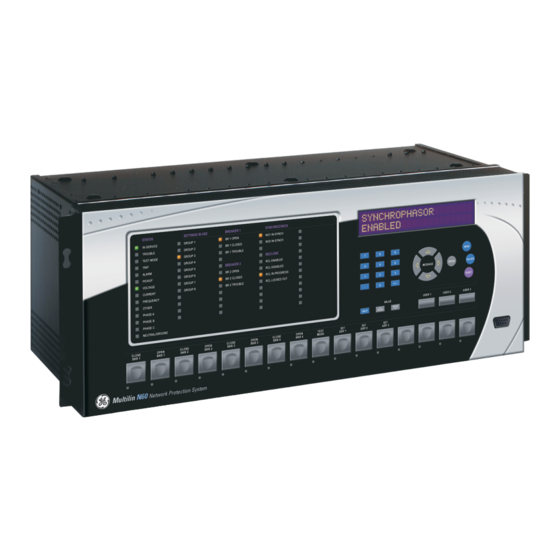
LED panel 2 LED panel 3 Display Front panel RS232 port Small user-programmable User-programmable Keypad (control) pushbuttons 1 to 7 pushbuttons 1 to 12 827801A7.CDR Figure 4–16: UR-SERIES STANDARD HORIZONTAL FACEPLATE PANELS GE Multilin N60 Network Stability and Synchrophasor Measurement System 4-13... -
Page 106: Led Indicators
• PHASE A: This LED indicates phase A was involved. • PHASE B: This LED indicates phase B was involved. • PHASE C: This LED indicates phase C was involved. 4-14 N60 Network Stability and Synchrophasor Measurement System GE Multilin... - Page 107 ORed to turn on or off the phase A, B or C LEDs. • VOLTAGE: Indicates voltage was involved. • CURRENT: Indicates current was involved. • FREQUENCY: Indicates frequency was involved. • OTHER: Indicates a composite function was involved. GE Multilin N60 Network Stability and Synchrophasor Measurement System 4-15...
- Page 108 LEDs are fully user-programmable. The default labels can be replaced by user-printed labels for both panels as explained in the following section. 842785A1.CDR Figure 4–20: LED PANEL 2 (DEFAULT LABELS) 4-16 N60 Network Stability and Synchrophasor Measurement System GE Multilin...
-
Page 109: Custom Labeling Of Leds
EnerVista UR Setup software is installed and operational. • The N60 settings have been saved to a settings file. • The N60 front panel label cutout sheet (GE Multilin part number 1006-0047) has been downloaded from http:// www.GEindustrial.com/multilin/support/ur and printed. - Page 110 The following procedure describes how to remove the LED labels from the N60 enhanced front panel and insert the custom labels. Use the knife to lift the LED label and slide the label tool underneath. Make sure the bent tabs are pointing away from the relay. 4-18 N60 Network Stability and Synchrophasor Measurement System GE Multilin...
- Page 111 Slide the new LED label inside the pocket until the text is properly aligned with the LEDs, as shown below. The following procedure describes how to remove the user-programmable pushbutton labels from the N60 enhanced front panel and insert the custom labels. GE Multilin N60 Network Stability and Synchrophasor Measurement System 4-19...
- Page 112 Slide the label tool under the user-programmable pushbutton label until the tabs snap out as shown below. This will attach the label tool to the user-programmable pushbutton label. Remove the tool and attached user-programmable pushbutton label as shown below. 4-20 N60 Network Stability and Synchrophasor Measurement System GE Multilin...
- Page 113 The panel templates provide relative LED locations and located example text (x) edit boxes. The following procedure demonstrates how to install/uninstall the custom panel labeling. Remove the clear Lexan Front Cover (GE Multilin part number: 1501-0014). Push in...
-
Page 114: Display
Microsoft Word 97 or later software for editing the template. • 1 each of: 8.5" x 11" white paper, exacto knife, ruler, custom display module (GE Multilin Part Number: 1516-0069), and a custom module cover (GE Multilin Part Number: 1502-0015). -
Page 115: Menus
Each press of the MENU key advances through the following main heading pages: • Actual values. • Settings. • Commands. • Targets. • User displays (when enabled). GE Multilin N60 Network Stability and Synchrophasor Measurement System 4-23... - Page 116 TIME: 1.0 s To view the remaining settings associated with the Display Properties subheader, DEFAULT MESSAGE repeatedly press the MESSAGE DOWN key. The last message appears as shown. INTENSITY: 25% 4-24 N60 Network Stability and Synchrophasor Measurement System GE Multilin...
-
Page 117: Changing Settings
Text settings have data values which are fixed in length, but user-defined in character. They may be comprised of upper case letters, lower case letters, numerals, and a selection of special characters. GE Multilin N60 Network Stability and Synchrophasor Measurement System... -
Page 118: Settings
When the "NEW SETTING HAS BEEN STORED" message appears, the relay will be in "Programmed" state and the In Service LED will turn on. e) ENTERING INITIAL PASSWORDS The N60 supports password entry from a local or remote connection. 4-26 N60 Network Stability and Synchrophasor Measurement System GE Multilin... - Page 119 FlexLogic™ operand will be set to “On” and the N60 will not allow settings or com- LOCAL ACCESS DENIED mand level access via the faceplate interface for the next five minutes, or in the event that an incorrect Command Or Set- GE Multilin N60 Network Stability and Synchrophasor Measurement System 4-27...
- Page 120 N60 will not allow Settings or Command access via the any external communications interface for the next ten minutes. FlexLogic™ operand will be set to “Off” after the expiration of the ten-minute timeout. REMOTE ACCESS DENIED 4-28 N60 Network Stability and Synchrophasor Measurement System GE Multilin...
-
Page 121: Overview
INSTALLATION See page 5-65. SETTINGS AC INPUTS See page 5-68. SYSTEM SETUP POWER SYSTEM See page 5-70. SIGNAL SOURCES See page 5-71. GE Multilin N60 Network Stability and Synchrophasor Measurement System... - Page 122 SELECTOR SWITCH See page 5-144. UNDERFREQUENCY See page 5-150. OVERFREQUENCY See page 5-151. SYNCHROCHECK See page 5-152. DIGITAL ELEMENTS See page 5-156. N60 Network Stability and Synchrophasor Measurement System GE Multilin...
- Page 123 See page 5-189. DIRECT ANALOGS See page 5-192. DIRECT INTEGERS See page 5-194. TELEPROTECTION See page 5-196. IEC 61850 See page 5-198. GOOSE ANALOGS GE Multilin N60 Network Stability and Synchrophasor Measurement System...
-
Page 124: Introduction To Elements
300 / 5 A and CT2 = 100 / 5 A, then in order to sum these, CT2 is scaled to the CT1 ratio. In this case, the base quantity will be 5 A secondary or 300 A primary. N60 Network Stability and Synchrophasor Measurement System GE Multilin... -
Page 125: Introduction To Ac Sources
CT and VT input channels, by selecting the parameter to measure. A mechanism is provided to specify the AC parameter (or group of parameters) used as the input to protection/control comparators and some metering elements. GE Multilin N60 Network Stability and Synchrophasor Measurement System... - Page 126 CT1 and CT2 and can name this source as “Wdg1 I”. Once the sources have been configured, the user has them available as selections for the choice of input signal for the pro- tection elements and as metered quantities. N60 Network Stability and Synchrophasor Measurement System GE Multilin...
- Page 127 CTs on each of two breakers is required to measure the winding current flow. GE Multilin N60 Network Stability and Synchrophasor Measurement System...
-
Page 128: Product Setup
(via the setting and command level access timeout settings). The remote setting and command ses- sions are initiated by the user through the EnerVista UR Setup software and are disabled either by the user or by timeout. N60 Network Stability and Synchrophasor Measurement System GE Multilin... - Page 129 If an entered password is lost (or forgotten), consult the factory with the corresponding ENCRYPTED PASSWORD If the setting and command passwords are identical, then this one password allows access to both com- mands and settings. NOTE GE Multilin N60 Network Stability and Synchrophasor Measurement System...
- Page 130 Range: 2 to 5 in steps of 1 INVALID ATTEMPTS MESSAGE BEFORE LOCKOUT: 3 Range: 5 to 60 minutes in steps of 1 PASSWORD LOCKOUT MESSAGE DURATION: 5 min The following access supervision settings are available. 5-10 N60 Network Stability and Synchrophasor Measurement System GE Multilin...
- Page 131 UNAUTHORIZED ACCESS • REMOTE SETTING AUTH: This setting is used for remote (Ethernet or RS485 interfaces) setting access supervision. GE Multilin N60 Network Stability and Synchrophasor Measurement System 5-11...
-
Page 132: Display Properties
Range: 0.002 to 0.020 pu in steps of 0.001 CURRENT CUT-OFF MESSAGE LEVEL: 0.020 pu Range: 0.1 to 1.0 V secondary in steps of 0.1 VOLTAGE CUT-OFF MESSAGE LEVEL: 1.0 V 5-12 N60 Network Stability and Synchrophasor Measurement System GE Multilin... - Page 133 : “1.0 V” VOLTAGE CUT-OFF LEVEL : “100 A” PHASE CT PRIMARY : “66.4 V” PHASE VT SECONDARY : “208.00 : 1" PHASE VT RATIO : “Delta”. PHASE VT CONNECTION GE Multilin N60 Network Stability and Synchrophasor Measurement System 5-13...
-
Page 134: Clear Relay Records
Set the properties for user-programmable pushbutton 1 by making the following changes in the SETTINGS PRODUCT menu: SETUP USER-PROGRAMMABLE PUSHBUTTONS USER PUSHBUTTON 1 “Self-reset” PUSHBUTTON 1 FUNCTION: “0.20 s” PUSHBTN 1 DROP-OUT TIME: 5-14 N60 Network Stability and Synchrophasor Measurement System GE Multilin... -
Page 135: Communications
RS485 port. The rear COM2 port is RS485. The RS485 ports have settings for baud rate and parity. It is important that these parameters agree with the settings used on the computer or other equipment that is connected to these ports. Any of GE Multilin N60 Network Stability and Synchrophasor Measurement System... - Page 136 1. Refer to Appendix B for more information on the Modbus protocol. Changes to the setting will not take effect until the N60 is restarted. MODBUS TCP PORT NUMBER NOTE 5-16 N60 Network Stability and Synchrophasor Measurement System GE Multilin...
- Page 137 Range: 0 to 100000000 in steps of 1 DNP OTHER DEFAULT MESSAGE DEADBAND: 30000 Range: 1 to 10080 min. in steps of 1 DNP TIME SYNC IIN MESSAGE PERIOD: 1440 min GE Multilin N60 Network Stability and Synchrophasor Measurement System 5-17...
- Page 138 NOTE settings can force the N60 to respond to a maximum of five specific DNP masters. The DNP NETWORK CLIENT ADDRESS settings in this sub-menu are shown below. 5-18 N60 Network Stability and Synchrophasor Measurement System GE Multilin...
- Page 139 (for circuit breakers) or raise/lower (for tap changers) using a single control point. That is, the DNP master can operate a single point for both trip and close, or raise and lower, operations. The N60 can be configured to sup- GE Multilin N60 Network Stability and Synchrophasor Measurement System...
- Page 140 Up to 256 analog input points can be configured for the DNP or IEC 60870-5-104 protocols. The analog point list is config- ured by assigning an appropriate FlexAnalog parameter to each point. Refer to Appendix A: FlexAnalog Parameters for the full range of assignable parameters. 5-20 N60 Network Stability and Synchrophasor Measurement System GE Multilin...
- Page 141 PATH: SETTINGS PRODUCT SETUP COMMUNICATIONS IEC 61850 PROTOCOL GSSE/GOOSE CONFIGURATION GSSE / GOOSE TRANSMISSION CONFIGURATION RECEPTION MESSAGE The main transmission menu is shown below: GE Multilin N60 Network Stability and Synchrophasor Measurement System 5-21...
- Page 142 IEC 61850 GSSE application ID name string sent as part of each GSSE message. This GSSE ID string identifies the GSSE message to the receiving device. In N60 releases previous to 5.0x, this name string was repre- sented by the setting. RELAY NAME 5-22 N60 Network Stability and Synchrophasor Measurement System GE Multilin...
- Page 143 ID for each GOOSE sending device. This value can be left at its default if the feature is not required. Both the GOOSE VLAN settings are required by IEC 61850. PRIORITY GOOSE ETYPE APPID GE Multilin N60 Network Stability and Synchrophasor Measurement System 5-23...
- Page 144 The aggressive scheme is only supported in fast type 1A GOOSE messages (GOOSEOut 1 and GOOSEOut 2). For slow GOOSE messages (GOOSEOut 3 to GOOSEOut 8) the aggressive scheme is the same as the medium scheme. 5-24 N60 Network Stability and Synchrophasor Measurement System GE Multilin...
- Page 145 Configure the transmission dataset. Configure the GOOSE service settings. Configure the data. The general steps required for reception configuration are: Configure the reception dataset. Configure the GOOSE service settings. Configure the data. GE Multilin N60 Network Stability and Synchrophasor Measurement System 5-25...
- Page 146 Configure the GOOSE service settings by making the following changes in the INPUTS/OUTPUTS REMOTE DEVICES settings menu: REMOTE DEVICE 1 – to match the GOOSE ID string for the transmitting device. Enter “GOOSEOut_1”. REMOTE DEVICE 1 ID 5-26 N60 Network Stability and Synchrophasor Measurement System GE Multilin...
- Page 147 The status value for GGIO1.ST.Ind1.stVal is determined by the FlexLogic™ operand assigned to GGIO1 indication 1. Changes to this operand will result in the transmission of GOOSE messages con- taining the defined dataset. GE Multilin N60 Network Stability and Synchrophasor Measurement System 5-27...
- Page 148 LOCATION: Location MESSAGE Range: 1 to 65535 in steps of 1 IEC/MMS TCP PORT MESSAGE NUMBER: Range: Disabled, Enabled INCLUDE NON-IEC MESSAGE DATA: Enabled Range: Disabled, Enabled SERVER SCANNING: MESSAGE Disabled 5-28 N60 Network Stability and Synchrophasor Measurement System GE Multilin...
- Page 149 “cVal” values from the associated “instmag” and “instcVal” values. The “mag” and “cVal” values are used for the IEC 61850 buffered and unbuffered reports. These settings correspond to the associated “db” data items in the CF functional con- GE Multilin N60 Network Stability and Synchrophasor Measurement System...
- Page 150 The GGIO2 control configuration settings are used to set the control model for each input. The available choices are “0” (status only), “1” (direct control), and “2” (SBO with normal security). The GGIO2 control points are used to control the N60 virtual inputs. 5-30 N60 Network Stability and Synchrophasor Measurement System GE Multilin...
- Page 151 ANALOG IN 1 MAX: This setting defines the maximum value for each analog value. Refer to IEC 61850-7-1 and 61850-7-3 for details. This maximum value is used to determine the deadband. The deadband is used in the determi- nation of the deadbanded magnitude from the instantaneous magnitude. GE Multilin N60 Network Stability and Synchrophasor Measurement System 5-31...
- Page 152 LLN0 if a user needs some (but not all) data from already existing GGIO1, GGIO4, and MMXU4 points and their quantity is not greater than 64 minus the number items in this dataset. 5-32 N60 Network Stability and Synchrophasor Measurement System GE Multilin...
- Page 153 XCBR operating counter status attribute (OpCnt) increments with every operation. Frequent breaker operation may result in very large OpCnt values over time. This setting allows the OpCnt to be reset to “0” for XCBR1. GE Multilin N60 Network Stability and Synchrophasor Measurement System...
- Page 154 UR and a computer to an ethernet network. The main menu will be displayed in the web browser on the computer simply by entering the IP address of the N60 into the “Address” box on the web browser. 5-34 N60 Network Stability and Synchrophasor Measurement System GE Multilin...
- Page 155 “Enabled”, the DNP protocol will not be operational. When this setting is changed it will not NOTE become active until power to the relay has been cycled (off-to-on). GE Multilin N60 Network Stability and Synchrophasor Measurement System 5-35...
- Page 156 The client software (EnerVista UR Setup, for example) is the preferred interface to configure these settings. through settings allow Ethernet switch module events to be logged in the event PORT 1 EVENTS PORT 6 EVENTS recorder. 5-36 N60 Network Stability and Synchrophasor Measurement System GE Multilin...
-
Page 157: Modbus User Map
Range: Sunday to Saturday (all days of the week) DST STOP DAY: MESSAGE Sunday Range: First, Second, Third, Fourth, Last DST STOP DAY MESSAGE INSTANCE: First Range: 0:00 to 23:00 DST STOP HOUR: MESSAGE 2:00 GE Multilin N60 Network Stability and Synchrophasor Measurement System 5-37... -
Page 158: Oscillography
See the ACTUAL VALUES menu to view the number of cycles captured per record. The following table provides sam- RECORDS OSCILLOGRAPHY ple configurations with corresponding cycles/record. 5-38 N60 Network Stability and Synchrophasor Measurement System GE Multilin... - Page 159 DIGITAL 1(63) CHANNEL each oscillography trace depends in part on the number of parameters selected here. Parameters set to “Off” are ignored. Upon startup, the relay will automatically prepare the parameter list. GE Multilin N60 Network Stability and Synchrophasor Measurement System 5-39...
- Page 160 IB signal on terminal 2 of the CT/VT module in slot F. If there are no CT/VT modules and analog input modules, no analog traces will appear in the file; only the digital traces will appear. 5-40 N60 Network Stability and Synchrophasor Measurement System GE Multilin...
-
Page 161: Data Logger
254460 s 3600000 ms 2727.5 235645200 s 340.9 29455200 s 26182800 s Changing any setting affecting data logger operation will clear any data that is currently in the log. NOTE GE Multilin N60 Network Stability and Synchrophasor Measurement System 5-41... -
Page 162: Demand
(EQ 5.6) – where: d = demand value after applying input quantity for time t (in minutes) D = input quantity (constant), and k = 2.3 / thermal 90% response time. 5-42 N60 Network Stability and Synchrophasor Measurement System GE Multilin... - Page 163 TRIP & ALARM See page 5–46. MESSAGE LEDS USER-PROGRAMMABLE See page 5–46. MESSAGE LED 1 USER-PROGRAMMABLE MESSAGE LED 2 USER-PROGRAMMABLE MESSAGE LED 48 GE Multilin N60 Network Stability and Synchrophasor Measurement System 5-43...
-
Page 164: User-Programmable Leds
The test responds to the position and rising edges of the control input defined by the set- LED TEST CONTROL ting. The control pulses must last at least 250 ms to take effect. The following diagram explains how the test is executed. 5-44 N60 Network Stability and Synchrophasor Measurement System GE Multilin... - Page 165 2. Once stage 2 has started, the pushbutton can be released. When stage 2 is completed, stage 3 will automatically start. The test may be aborted at any time by pressing the pushbutton. GE Multilin N60 Network Stability and Synchrophasor Measurement System...
- Page 166 BREAKER 1 OPEN LED 21 operand LED 10 operand BREAKER 1 CLOSED LED 22 operand LED 11 operand BREAKER 1 TROUBLE LED 23 operand LED 12 operand LED 24 operand 5-46 N60 Network Stability and Synchrophasor Measurement System GE Multilin...
-
Page 167: Control Pushbuttons
Firmware revisions 3.2x and older use these three pushbuttons for manual breaker control. This functionality has been retained – if the breaker control feature is configured to use the three pushbuttons, they cannot be used as user-program- mable control pushbuttons. GE Multilin N60 Network Stability and Synchrophasor Measurement System 5-47... - Page 168 BREAKERS/BREAKER 1/ BREAKER 1 PUSHBUTTON CONTROL Enabled=1 TIMER FLEXLOGIC OPERAND SYSTEM SETUP/ BREAKERS/BREAKER 2/ CONTROL PUSHBTN 1 ON 100 msec BREAKER 2 PUSHBUTTON CONTROL 842010A2.CDR Enabled=1 Figure 5–7: CONTROL PUSHBUTTON LOGIC 5-48 N60 Network Stability and Synchrophasor Measurement System GE Multilin...
-
Page 169: User-Programmable Pushbuttons
FlexLogic™ equations, protection elements, and control elements. Typical applications include breaker control, autorecloser blocking, and setting groups changes. The user-programmable pushbuttons are under the control level of password protection. The user-configurable pushbuttons for the enhanced faceplate are shown below. GE Multilin N60 Network Stability and Synchrophasor Measurement System 5-49... - Page 170 The pulse duration of the remote set, remote reset, or local pushbutton must be at least 50 ms to operate the push- button. This allows the user-programmable pushbuttons to properly operate during power cycling events and vari- NOTE ous system disturbances that may cause transient assertion of the operating signals. 5-50 N60 Network Stability and Synchrophasor Measurement System GE Multilin...
- Page 171 PUSHBTN 1 RESET • PUSHBTN 1 LOCAL: This setting assigns the FlexLogic™ operand serving to inhibit pushbutton operation from the front panel pushbuttons. This locking functionality is not applicable to pushbutton autoreset. GE Multilin N60 Network Stability and Synchrophasor Measurement System 5-51...
- Page 172 “High Priority” or “Normal”. PUSHBTN 1 MESSAGE • PUSHBUTTON 1 EVENTS: If this setting is enabled, each pushbutton state change will be logged as an event into event recorder. 5-52 N60 Network Stability and Synchrophasor Measurement System GE Multilin...
- Page 173 SETTING Autoreset Delay Autoreset Function = Enabled = Disabled SETTING Drop-Out Timer TIMER FLEXLOGIC OPERAND 200 ms PUSHBUTTON 1 ON 842021A3.CDR Figure 5–10: USER-PROGRAMMABLE PUSHBUTTON LOGIC (Sheet 1 of 2) GE Multilin N60 Network Stability and Synchrophasor Measurement System 5-53...
-
Page 174: Flex State Parameters
PRODUCT SETUP FLEX STATE PARAMETERS Range: FlexLogic™ operand FLEX STATE PARAMETER PARAMETERS Range: FlexLogic™ operand PARAMETER MESSAGE Range: FlexLogic™ operand PARAMETER MESSAGE Range: FlexLogic™ operand PARAMETER 256: MESSAGE 5-54 N60 Network Stability and Synchrophasor Measurement System GE Multilin... -
Page 175: User-Definable Displays
INVOKE AND SCROLL play, not at the first user-defined display. The pulses must last for at least 250 ms to take effect. INVOKE AND SCROLL GE Multilin N60 Network Stability and Synchrophasor Measurement System 5-55... - Page 176 While viewing a user display, press the ENTER key and then select the ‘Yes” option to remove the display from the user display list. Use the MENU key again to exit the user displays menu. 5-56 N60 Network Stability and Synchrophasor Measurement System GE Multilin...
-
Page 177: Direct Inputs/Outputs
CRC ALARM CH2 See page 5–63. MESSAGE UNRETURNED See page 5–64. MESSAGE MESSAGES ALARM CH1 UNRETURNED See page 5–64. MESSAGE MESSAGES ALARM CH2 GE Multilin N60 Network Stability and Synchrophasor Measurement System 5-57... - Page 178 Delivery time for direct input and output messages is approximately 0.2 of a power system cycle at 128 kbps and 0.4 of a power system cycle at 64 kbps, per each ‘bridge’. 5-58 N60 Network Stability and Synchrophasor Measurement System GE Multilin...
- Page 179 The following application examples illustrate the basic concepts for direct input and output configuration. Please refer to the Inputs and outputs section in this chapter for information on configuring FlexLogic™ operands (flags, bits) to be exchanged. GE Multilin N60 Network Stability and Synchrophasor Measurement System...
- Page 180 UR IED 4 UR IED 2 UR IED 3 842712A1.CDR Figure 5–13: SAMPLE INTERLOCKING BUSBAR PROTECTION SCHEME For increased reliability, a dual-ring configuration (shown below) is recommended for this application. 5-60 N60 Network Stability and Synchrophasor Measurement System GE Multilin...
- Page 181 The complete application requires addressing a number of issues such as failure of both the communications rings, failure or out-of-service conditions of one of the relays, etc. Self-monitoring flags of the direct inputs and outputs feature would be primarily used to address these concerns. GE Multilin N60 Network Stability and Synchrophasor Measurement System 5-61...
- Page 182 Inputs and outputs section. A blocking pilot-aided scheme should be implemented with more security and, ideally, faster message delivery time. This could be accomplished using a dual-ring configuration as shown below. 5-62 N60 Network Stability and Synchrophasor Measurement System GE Multilin...
- Page 183 FlexLogic™ operand is set. When the total message counter reaches the user-defined maximum specified by the set- CRC ALARM CH1 MESSAGE COUNT ting, both the counters reset and the monitoring process is restarted. GE Multilin N60 Network Stability and Synchrophasor Measurement System 5-63...
- Page 184 The unreturned messages alarm function is available on a per-channel basis and is active only in the ring configuration. The total number of unreturned input and output messages is available as the ACTUAL VALUES STATUS DIRECT actual value. INPUTS UNRETURNED MSG COUNT CH1 5-64 N60 Network Stability and Synchrophasor Measurement System GE Multilin...
-
Page 185: Teleprotection
5.2.18 INSTALLATION PATH: SETTINGS PRODUCT SETUP INSTALLATION Range: Not Programmed, Programmed INSTALLATION RELAY SETTINGS: Not Programmed Range: up to 20 alphanumeric characters RELAY NAME: MESSAGE Relay-1 GE Multilin N60 Network Stability and Synchrophasor Measurement System 5-65... - Page 186 This name will appear on generated reports. This name RELAY NAME is also used to identify specific devices which are engaged in automatically sending/receiving data over the Ethernet com- munications channel using the IEC 61850 protocol. 5-66 N60 Network Stability and Synchrophasor Measurement System GE Multilin...
-
Page 187: Remote Resources Configuration
Brick. For additional information on how to configure a relay with a process bus module, please refer to GE publication number GEK-113500: HardFiber System Instruction Manual. GE Multilin N60 Network Stability and Synchrophasor Measurement System 5-67... -
Page 188: Ac Inputs
1 pu will operate on 1000 A primary. The same rule applies for current sums from CTs with different secondary taps (5 A and 1 A). 5-68 N60 Network Stability and Synchrophasor Measurement System GE Multilin... - Page 189 On a 14.4 kV system with a delta connection and a VT primary to secondary turns ratio of 14400:120, the voltage value entered would be 120; that is, 14400 / 120. GE Multilin N60 Network Stability and Synchrophasor Measurement System...
-
Page 190: Power System
The frequency tracking feature will function only when the N60 is in the “Programmed” mode. If the N60 is “Not Pro- grammed”, then metering values will be available but may exhibit significant errors. NOTE 5-70 N60 Network Stability and Synchrophasor Measurement System GE Multilin... -
Page 191: Signal Sources
(to prevent maloperation as a result of the wrong settings), and starting oscillography data capture. A dis- turbance detector is provided for each source. The 50DD function responds to the changes in magnitude of the sequence currents. The disturbance detector scheme logic is as follows: GE Multilin N60 Network Stability and Synchrophasor Measurement System 5-71... - Page 192 CT/VT inputs that are used to provide the data. DSP Bank Source 1 Source 2 Amps Amps Source 3 51BF-1 51BF-2 Volts Amps Amps Volts Source 4 UR Relay Figure 5–20: EXAMPLE USE OF SOURCES 5-72 N60 Network Stability and Synchrophasor Measurement System GE Multilin...
-
Page 193: Breakers
Range: 0.000 to 65.535 s in steps of 0.001 MANUAL CLOSE RECAL1 MESSAGE TIME: 0.000 s Range: FlexLogic™ operand BREAKER 1 OUT OF SV: MESSAGE Range: Disabled, Enabled BREAKER 1 EVENTS: MESSAGE Disabled GE Multilin N60 Network Stability and Synchrophasor Measurement System 5-73... - Page 194 MANUAL CLOSE RECAL1 TIME: This setting specifies the interval required to maintain setting changes in effect after an operator has initiated a manual close command to operate a circuit breaker. • BREAKER 1 OUT OF SV: Selects an operand indicating that breaker 1 is out-of-service. 5-74 N60 Network Stability and Synchrophasor Measurement System GE Multilin...
- Page 195 Figure 5–21: DUAL BREAKER CONTROL SCHEME LOGIC (Sheet 1 of 2) IEC 61850 functionality is permitted when the N60 is in “Programmed” mode and not in the local control mode. NOTE GE Multilin N60 Network Stability and Synchrophasor Measurement System 5-75...
- Page 196 5.4 SYSTEM SETUP 5 SETTINGS Figure 5–22: DUAL BREAKER CONTROL SCHEME LOGIC (Sheet 2 of 2) 5-76 N60 Network Stability and Synchrophasor Measurement System GE Multilin...
-
Page 197: Disconnect Switches
SWITCH 1 MODE: This setting selects “3-Pole” mode, where all disconnect switch poles are operated simultaneously, or “1-Pole” mode where all disconnect switch poles are operated either independently or simultaneously. GE Multilin N60 Network Stability and Synchrophasor Measurement System 5-77... - Page 198 This allows for non-simultaneous operation of the poles. IEC 61850 functionality is permitted when the N60 is in “Programmed” mode and not in the local control mode. NOTE 5-78 N60 Network Stability and Synchrophasor Measurement System GE Multilin...
- Page 199 5 SETTINGS 5.4 SYSTEM SETUP Figure 5–23: DISCONNECT SWITCH SCHEME LOGIC GE Multilin N60 Network Stability and Synchrophasor Measurement System 5-79...
-
Page 200: Phasor Measurement Unit
The specifics of implementation by model number is summarized in the table below. Table 5–6: IMPLEMENTATION BY MODEL NUMBER MODEL NUMBER OF NUMBER OF NUMBER OF ANALOG PMUS AGGREGATORS INPUTS D60, F60, G60, L30, L90, T60 5-80 N60 Network Stability and Synchrophasor Measurement System GE Multilin... - Page 201 MESSAGE AGGREGATORS PMU 1 See page 5-88. MESSAGE CALIBRATION PMU 1 See page 5-89. MESSAGE TRIGGERING PMU 1 See page 5-96. MESSAGE RECORDING GE Multilin N60 Network Stability and Synchrophasor Measurement System 5-81...
- Page 202 PMU 1 D-CH-1: MESSAGE Default: Off Range: 16 character ASCII string PMU 1 D-CH-1 MESSAGE Default: DigChannel1 NM: DigChannel1 Range: Off, On PMU 1 D-CH-1 MESSAGE Default: Off NORMAL STATE: Off 5-82 N60 Network Stability and Synchrophasor Measurement System GE Multilin...
- Page 203 Note that for firmware 6.0 a maximum of two PMUs can be set to a reporting rate of 120 Hz for a 60 Hz system (or 100 Hz for 50 Hz system). GE Multilin N60 Network Stability and Synchrophasor Measurement System...
- Page 204 Same filter as above 100 Hz 25:1 4 Hz 2 Hz Same filter as above 100 Hz 50:1 2 Hz 1 Hz Same filter as above 100 Hz 100:1 1 Hz 5-84 N60 Network Stability and Synchrophasor Measurement System GE Multilin...
- Page 205 PMU1 D-CH-1 NORMAL STATE to PMU1 D-CH-16 NORMAL STATE: These settings allow for specifying a normal state for each digital channel. These states are transmitted in configuration frames to the data concentrator. GE Multilin N60 Network Stability and Synchrophasor Measurement System...
- Page 206 5 second timer is re-started. This setting enables or disables the control. When enabled, all 16 oper- ands for each aggregator are active; when disabled all 16 operands for each aggregator remain reset. 5-86 N60 Network Stability and Synchrophasor Measurement System GE Multilin...
- Page 207 Note: If changes are made to PMU settings the PMU must be removed from the aggregator and the settings saved and then the PMU should be added back into the aggregator and the settings saved such that the new PMU set- tings take effect. GE Multilin N60 Network Stability and Synchrophasor Measurement System 5-87...
- Page 208 VTs, CTs, and cabling. The setting values are effectively added to the measured angles. Therefore, enter a positive correction of the secondary signal lags the true signal; and negative value if the secondary signal leads the true signal. 5-88 N60 Network Stability and Synchrophasor Measurement System GE Multilin...
- Page 209 The pre-configured triggers could be augmented with a user-specified condition built freely using programmable logic of the relay. The entire triggering logic is refreshed once every two power system cycles. GE Multilin N60 Network Stability and Synchrophasor Measurement System 5-89...
- Page 210 • PMU 1 FREQ TRIGGER LOW-FREQ: This setting specifies the low threshold for the abnormal frequency trigger. The comparator applies a 0.03 Hz hysteresis. 5-90 N60 Network Stability and Synchrophasor Measurement System GE Multilin...
- Page 211 AB, BC, and CA) are processed independently and could trigger the recorder. A minimum voltage supervision of 0.1 pu is implemented to prevent pickup on a de-energized circuit, similarly to the undervoltage protection element. GE Multilin N60 Network Stability and Synchrophasor Measurement System...
- Page 212 PMU 1 CURR TRIGGER PICKUP: This setting specifies the pickup threshold for the overcurrent trigger, in per unit of the PMU source. A value of 1 pu is a nominal primary current. The comparator applies a 3% hysteresis. 5-92 N60 Network Stability and Synchrophasor Measurement System GE Multilin...
- Page 213 PMU 1 POWER TRIGGER ACTIVE: This setting specifies the pickup threshold for the active power of the source. For single-phase power, 1 pu is a product of 1 pu voltage and 1 pu current, or the product of nominal secondary voltage, GE Multilin N60 Network Stability and Synchrophasor Measurement System...
- Page 214 S > APPARENT PICKUP APPARENT POWER, SB S > APPARENT PICKUP APPARENT POWER, SC S > APPARENT PICKUP 3P APPARENT POWER, S S > 3*(APPARENT PICKUP) 847003A1.CDR Figure 5–29: POWER TRIGGER SCHEME LOGIC 5-94 N60 Network Stability and Synchrophasor Measurement System GE Multilin...
- Page 215 PMU 1 df/dt TRIGGER DPO TIME: PMU 1 SIGNAL FLEXLOGIC OPERAND SOURCE: df/dt > RAISE PMU 1 ROCOF TRIGGER ROCOF, df/dt –df/dt > FALL 847000A1.CDR Figure 5–30: RATE OF CHANGE OF FREQUENCY TRIGGER SCHEME LOGIC GE Multilin N60 Network Stability and Synchrophasor Measurement System 5-95...
- Page 216 PMU 1 TIMED TRIGGER POSITION: This setting specifies the amount of pre-trigger data as a percent of the entire record. This setting applies only to the timed mode of recording. 5-96 N60 Network Stability and Synchrophasor Measurement System GE Multilin...
-
Page 217: Introduction To Flexlogic™
Traditionally, protective relay logic has been relatively limited. Any unusual applications involving interlocks, blocking, or supervisory functions had to be hard-wired using contact inputs and outputs. FlexLogic™ minimizes the requirement for auxiliary components and wiring while making more complex schemes possible. GE Multilin N60 Network Stability and Synchrophasor Measurement System 5-97... - Page 218 The virtual input is presently in the ON state. Virtual Output Virt Op 1 On The virtual output is presently in the set state (i.e. evaluation of the equation which produces this virtual output results in a "1"). 5-98 N60 Network Stability and Synchrophasor Measurement System GE Multilin...
- Page 219 Bit 7 of eight-bit switch 1 asserted (the most significant bit) 8BIT SWITCH 2 to 8BIT Same set of operands as shown for 8 BIT SWITCH 1 above SWITCH 6 GE Multilin N60 Network Stability and Synchrophasor Measurement System 5-99...
- Page 220 FREQ RATE 1 OP The frequency rate of change 1 element has operated FREQ RATE 2 to FREQ RATE 4 Same set of operands as shown for FREQ RATE 1 5-100 N60 Network Stability and Synchrophasor Measurement System GE Multilin...
- Page 221 Phase A of overvoltage 1 has dropped out PHASE OV1 DPO B Phase B of overvoltage 1 has dropped out PHASE OV1 DPO C Phase C of overvoltage 1 has dropped out GE Multilin N60 Network Stability and Synchrophasor Measurement System 5-101...
- Page 222 Setting group 3 is active SETTING GROUP ACT 4 Setting group 4 is active SETTING GROUP ACT 5 Setting group 5 is active SETTING GROUP ACT 6 Setting group 6 is active 5-102 N60 Network Stability and Synchrophasor Measurement System GE Multilin...
- Page 223 Synchrocheck 1 V2 is above the minimum live voltage SYNC 1 V2 BELOW MAX Synchrocheck 1 V2 is below the maximum dead voltage SYNC 2 Same set of operands as shown for SYNC 1 GE Multilin N60 Network Stability and Synchrophasor Measurement System 5-103...
- Page 224 Virt Ip 1 Flag is set, logic=1 Virtual inputs Virt Ip 2 Flag is set, logic=1 Virt Ip 3 Flag is set, logic=1 Virt Ip 64 Flag is set, logic=1 5-104 N60 Network Stability and Synchrophasor Measurement System GE Multilin...
- Page 225 Communications source of the reset command. RESET OP (OPERAND) Operand (assigned in the INPUTS/OUTPUTS RESETTING menu) source of the reset command. RESET OP (PUSHBUTTON) Reset key (pushbutton) source of the reset command. GE Multilin N60 Network Stability and Synchrophasor Measurement System 5-105...
- Page 226 ‘1’ 2 to 16 all inputs are ‘1’ 2 to 16 all inputs are ‘0’ NAND 2 to 16 any input is ‘0’ only one input is ‘1’ 5-106 N60 Network Stability and Synchrophasor Measurement System GE Multilin...
-
Page 227: Flexlogic™ Rules
If it is necessary to re-initialize FlexLogic™ during testing, for example, it is suggested to power the unit down and then back up. GE Multilin N60 Network Stability and Synchrophasor Measurement System... -
Page 228: Flexlogic™ Example
State=Pickup (200 ms) DIGITAL ELEMENT 2 Timer 1 State=Operated Time Delay on Pickup (800 ms) CONTACT INPUT H1c State=Closed VIRTUAL OUTPUT 3 827026A2.VSD Figure 5–33: LOGIC EXAMPLE WITH VIRTUAL OUTPUTS 5-108 N60 Network Stability and Synchrophasor Measurement System GE Multilin... - Page 229 Following the procedure outlined, start with parameter 99, as follows: 99: The final output of the equation is virtual output 3, which is created by the operator "= Virt Op n". This parameter is therefore "= Virt Op 3." GE Multilin N60 Network Stability and Synchrophasor Measurement System 5-109...
- Page 230 86: The upper input to OR #1 is operand “Virt Op 1 On". 85: The last parameter is used to set the latch, and is operand “Virt Op 4 On". 5-110 N60 Network Stability and Synchrophasor Measurement System GE Multilin...
- Page 231 In the following equation, virtual output 3 is used as an input to both latch 1 and timer 1 as arranged in the order shown below: DIG ELEM 2 OP Cont Ip H1c On AND(2) GE Multilin N60 Network Stability and Synchrophasor Measurement System 5-111...
-
Page 232: Flexlogic™ Equation Editor
TIMER 1 TYPE: This setting is used to select the time measuring unit. • TIMER 1 PICKUP DELAY: Sets the time delay to pickup. If a pickup delay is not required, set this function to "0". 5-112 N60 Network Stability and Synchrophasor Measurement System GE Multilin... -
Page 233: Flexelements™
The element can be programmed to respond either to a signal level or to a rate-of-change (delta) over a pre-defined period of time. The output operand is asserted when the operating signal is higher than a threshold or lower than a threshold as per user's choice. GE Multilin N60 Network Stability and Synchrophasor Measurement System 5-113... - Page 234 The FLEXELEMENT 1 DIRECTION following figure explains the application of the FLEXELEMENT 1 DIRECTION FLEXELEMENT 1 PICKUP FLEXELEMENT 1 HYS- settings. TERESIS 5-114 N60 Network Stability and Synchrophasor Measurement System GE Multilin...
- Page 235 FLEXELEMENT INPUT MODE = Signed; FlexElement 1 OpSig FLEXELEMENT 1 PKP FLEXELEMENT DIRECTION = Under; FLEXELEMENT INPUT MODE = Absolute; FlexElement 1 OpSig 842706A2.CDR Figure 5–41: FLEXELEMENT™ INPUT MODE SETTING GE Multilin N60 Network Stability and Synchrophasor Measurement System 5-115...
- Page 236 FLEXELEMENT 1 COMP MODE This setting specifies the pickup delay of the element. The setting FLEXELEMENT 1 PKP DELAY FLEXELEMENT 1 RST DELAY specifies the reset delay of the element. 5-116 N60 Network Stability and Synchrophasor Measurement System GE Multilin...
-
Page 237: Non-Volatile Latches
LATCH 1 ON Dominant LATCH 1 OFF Previous Previous SETTING State State LATCH 1 SET: Off=0 RESET 842005A1.CDR Figure 5–42: NON-VOLATILE LATCH OPERATION TABLE (N = 1 to 16) AND LOGIC GE Multilin N60 Network Stability and Synchrophasor Measurement System 5-117... -
Page 238: Flexmath
Each summator has six inputs and a scaling factor is provided for each input. The scaling factors can be set to +1 and –1 allowing straight addition and subtraction of the inputs. A FlexLogic™ operand provided for each input can dynamically include/exclude the input from calculations. 5-118 N60 Network Stability and Synchrophasor Measurement System GE Multilin... - Page 239 SUMMATOR 1 EVENTS: This setting is used to generate events for the summator. The event SUMMATOR 1 OPERATE is created on the rising edge of the FlexLogic™ operand. SUMMATOR 1 OP GE Multilin N60 Network Stability and Synchrophasor Measurement System 5-119...
- Page 240 OUTPUT > SUMMATOR PICKUP SUMMATOR OP SUMMATOR INPUT4 SUMMATOR SCALE4 SUMMATOR INPUT MODE SUMMATOR POS4 SUMMATOR INPUT5 SUMMATOR SCALE5 SUMMATOR POS5 SUMMATOR INPUT6 SUMMATOR SCALE6 SUMMATOR POS6 847006A1.CDR Figure 5–43: SUMMATOR LOGIC SCHEME 5-120 N60 Network Stability and Synchrophasor Measurement System GE Multilin...
-
Page 241: Overview
Each of the six setting group menus is identical. Setting group 1 (the default active group) automatically becomes active if no other group is active (see the Control elements section for additional details). GE Multilin N60 Network Stability and Synchrophasor Measurement System... -
Page 242: Power Swing Detect
Range: 0.10 to 500.00 ohms in steps of 0.01 POWER SWING MIDDLE MESSAGE LFT BLD: 100.00 Range: 0.10 to 500.00 ohms in steps of 0.01 POWER SWING INNER MESSAGE RGT BLD: 100.00 5-122 N60 Network Stability and Synchrophasor Measurement System GE Multilin... - Page 243 Two-step operation: If the two-step mode is selected, the sequence is identical, but it is the outer and inner character- istics that are used to time the power swing locus. GE Multilin N60 Network Stability and Synchrophasor Measurement System 5-123...
- Page 244 “Mho”, the element applies the right and left blinders as well. If the blinders are not required, their settings should be set high enough to effectively disable the blinders. Figure 5–44: POWER SWING DETECT MHO OPERATING CHARACTERISTICS 5-124 N60 Network Stability and Synchrophasor Measurement System GE Multilin...
- Page 245 FlexLogic™ operands are auxiliary operands that could be used to facilitate TMR3 PKP POWER SWING TMR4 PKP testing and special applications. • FlexLogic™ operand shall be used to block selected protection elements such as distance POWER SWING BLOCK functions. GE Multilin N60 Network Stability and Synchrophasor Measurement System 5-125...
- Page 246 POWER SWING QUAD REV REACH MID: This setting specifies the reverse reach of the middle quadrilateral charac- teristic. The angle of this reach impedance is specified by the setting. The setting is not used if POWER SWING FWD RCA the shape setting is “Mho”. 5-126 N60 Network Stability and Synchrophasor Measurement System GE Multilin...
- Page 247 The delayed trip occurs when the impedance leaves the outer charac- teristic. This time delay is provided for extra security and should be set considering the fastest expected power swing. GE Multilin N60 Network Stability and Synchrophasor Measurement System...
- Page 248 K_0, K_2 - three times the average change over last power cycle 842008A1.CDR K_1 - four times the average change over last power cycle Figure 5–48: POWER SWING DETECT SCHEME LOGIC (2 of 3) 5-128 N60 Network Stability and Synchrophasor Measurement System GE Multilin...
- Page 249 L1 AND L4 LATCHES ARE SET DOMINANT L2, L3 AND L5 LATCHES ARE RESET DOMINANT Off=0 FLEXLOGIC OPERAND POWER SWING OUTGOING 827841A4.CDR Figure 5–49: POWER SWING DETECT SCHEME LOGIC (3 of 3) GE Multilin N60 Network Stability and Synchrophasor Measurement System 5-129...
-
Page 250: Phase Current
The phase instantaneous overcurrent element may be used as an instantaneous element with no intentional delay or as a definite time element. The input current is the fundamental phasor magnitude. The phase instantaneous overcurrent timing curves are shown below for form-A contacts in a 60 Hz system. 5-130 N60 Network Stability and Synchrophasor Measurement System GE Multilin... - Page 251 PHASE IOC1 PKP SETTING PHASE IOC1 OP PHASE IOC1 BLOCK-B: PHASE IOC1 DPO Off = 0 SETTING 827033A6.VSD PHASE IOC1 BLOCK-C: Off = 0 Figure 5–51: PHASE INSTANTANEOUS OVERCURRENT 1 SCHEME LOGIC GE Multilin N60 Network Stability and Synchrophasor Measurement System 5-131...
-
Page 252: Voltage Elements
pickup where: T = operating time D = undervoltage delay setting (D = 0.00 operates instantaneously) V = secondary voltage applied to the relay = pickup level pickup 5-132 N60 Network Stability and Synchrophasor Measurement System GE Multilin... - Page 253 The minimum voltage setting selects the operating voltage below which the element is blocked (a setting of “0” will allow a dead source to be considered a fault condition). GE Multilin N60 Network Stability and Synchrophasor Measurement System...
- Page 254 The input voltage is the phase-to-phase voltage, either measured directly from delta-connected VTs or as cal- culated from phase-to-ground (wye) connected VTs. The specific voltages to be used for each phase are shown below. 5-134 N60 Network Stability and Synchrophasor Measurement System GE Multilin...
- Page 255 PHASE OV1 PKP 827066A7.CDR Figure 5–54: PHASE OVERVOLTAGE SCHEME LOGIC If the source VT is wye-connected, then the phase overvoltage pickup condition is Pickup for V and V NOTE GE Multilin N60 Network Stability and Synchrophasor Measurement System 5-135...
-
Page 256: Supervising Elements
OPEN POLE CURRENT PICKUP: This setting is used to select the pickup value of the phase current. The pickup set- ting is the minimum of the range and likely to be somewhat above of the charging current of the line. 5-136 N60 Network Stability and Synchrophasor Measurement System GE Multilin... - Page 257 OPEN POLE VOLTAGE SOURCE: DELTA VA < 75% Nominal VAG or VBG or VB < 75% Nominal VCG or VC < 75% Nominal 827047A6.CDR Figure 5–55: OPEN POLE DETECTOR SCHEME LOGIC GE Multilin N60 Network Stability and Synchrophasor Measurement System 5-137...
-
Page 258: Sensitive Directional Power
The operating quantity is displayed in the actual ACTUAL VALUES METERING SENSITIVE DIRECTIONAL POWER 1(2) value. The element has two independent (as to the pickup and delay settings) stages for alarm and trip, respectively. 5-138 N60 Network Stability and Synchrophasor Measurement System GE Multilin... - Page 259 SMIN < 0 SMIN > 0 OPERATE RESTRAIN RESTRAIN OPERATE RCA = 90 RCA = 270 SMIN > 0 SMIN < 0 842702A1.CDR Figure 5–57: DIRECTIONAL POWER ELEMENT SAMPLE APPLICATIONS GE Multilin N60 Network Stability and Synchrophasor Measurement System 5-139...
- Page 260 Three-phase reactive power (Q) DIR POWER 1 STG2 DPO DIR POWER 1 STG2 OP SETTING DIR POWER 1 STG2 DELAY: 100 ms 842003A3.CDR Figure 5–58: SENSITIVE DIRECTIONAL POWER SCHEME LOGIC 5-140 N60 Network Stability and Synchrophasor Measurement System GE Multilin...
-
Page 261: Overview
If more than one operate-type operand is required, it may be assigned directly from the trip bus menu. GE Multilin N60 Network Stability and Synchrophasor Measurement System... - Page 262 = Enabled TRIP BUS 1 BLOCK = Off SETTINGS TRIP BUS 1 LATCHING = Enabled TRIP BUS 1 RESET = Off FLEXLOGIC OPERAND RESET OP 842023A1.CDR Figure 5–60: TRIP BUS LOGIC 5-142 N60 Network Stability and Synchrophasor Measurement System GE Multilin...
-
Page 263: Setting Groups
The assigned operand is used to control the “On” state of a particular settings group. VIRTUAL OUTPUT 1 GE Multilin N60 Network Stability and Synchrophasor Measurement System 5-143... -
Page 264: Selector Switch
SELECTOR 1 3BIT ACK: MESSAGE Range: Restore, Synchronize, Sync/Restore SELECTOR 1 POWER-UP MESSAGE MODE: Restore Range: Self-reset, Latched, Disabled SELECTOR 1 TARGETS: MESSAGE Self-reset Range: Disabled, Enabled SELECTOR 1 EVENTS: MESSAGE Disabled 5-144 N60 Network Stability and Synchrophasor Measurement System GE Multilin... - Page 265 SELECTOR 1 3BIT A0, A1, and A2: These settings specify a three-bit control input of the selector. The three-bit con- trol word pre-selects the position using the following encoding convention: POSITION rest GE Multilin N60 Network Stability and Synchrophasor Measurement System 5-145...
- Page 266 The selector position pre-selected via the stepping up control input has not been confirmed before the time out. SELECTOR 1 BIT ALARM The selector position pre-selected via the three-bit control input has not been confirmed before the time out. 5-146 N60 Network Stability and Synchrophasor Measurement System GE Multilin...
- Page 267 POS 1 POS 2 POS 3 POS 4 POS 5 POS 6 POS 7 BIT 0 BIT 1 BIT 2 STP ALARM BIT ALARM ALARM 842737A1.CDR Figure 5–62: TIME-OUT MODE GE Multilin N60 Network Stability and Synchrophasor Measurement System 5-147...
- Page 268 Make the following changes to selector switch element in the SETTINGS CONTROL ELEMENTS SELECTOR SWITCH menu to assign control to user programmable pushbutton 1 and contact inputs 1 through 3: SELECTOR SWITCH 1 5-148 N60 Network Stability and Synchrophasor Measurement System GE Multilin...
- Page 269 SELECTOR 1 BIT ALARM 3-bit position out SELECTOR 1 ALARM SELECTOR 1 PWR ALARM SELECTOR 1 BIT 0 SELECTOR 1 BIT 1 SELECTOR 1 BIT 2 842012A2.CDR Figure 5–64: SELECTOR SWITCH LOGIC GE Multilin N60 Network Stability and Synchrophasor Measurement System 5-149...
-
Page 270: Underfrequency
0 < f PICKUP UNDERFREQ 1 OP UNDERFREQ 1 ACTUAL VALUES MIN VOLT / AMP: UNDERFREQ 1 SOURCE: ≥ Level Minimum VOLT / AMP Frequency 827079A8.CDR Figure 5–65: UNDERFREQUENCY SCHEME LOGIC 5-150 N60 Network Stability and Synchrophasor Measurement System GE Multilin... -
Page 271: Overfrequency
OVERFREQ 1 RESET OVERFREQ 1 PKP DELAY : Off = 0 OVERFREQ 1 DPO OVERFREQ 1 OP SETTING ≥ PICKUP OVERFREQ 1 SOURCE: Frequency 827832A5.CDR Figure 5–66: OVERFREQUENCY SCHEME LOGIC GE Multilin N60 Network Stability and Synchrophasor Measurement System 5-151... -
Page 272: Synchrocheck
F. This time can be calculated by: ------------------------------- - (EQ 5.12) 360 ----------------- - F 2 where: = phase angle difference in degrees; F = frequency difference in Hz. 5-152 N60 Network Stability and Synchrophasor Measurement System GE Multilin... - Page 273 SOURCE Y SOURCE Z Phase VTs and Phase VTs and Phase Phase Auxiliary VT Auxiliary VT Phase VTs and Phase VT Phase Phase Auxiliary VT Phase VT Phase VT Phase Phase GE Multilin N60 Network Stability and Synchrophasor Measurement System 5-153...
- Page 274 The relay will use the auxiliary voltage channel only if that channel is programmed as part of the Source and a three-phase set is not. 5-154 N60 Network Stability and Synchrophasor Measurement System GE Multilin...
- Page 275 5 SETTINGS 5.7 CONTROL ELEMENTS Figure 5–67: SYNCHROCHECK SCHEME LOGIC GE Multilin N60 Network Stability and Synchrophasor Measurement System 5-155...
-
Page 276: Digital Elements
Some versions of the digital input modules include an active voltage monitor circuit connected across form-A contacts. The voltage monitor circuit limits the trickle current through the output circuit (see technical specifications for form-A). 5-156 N60 Network Stability and Synchrophasor Measurement System GE Multilin... - Page 277 The settings to use digital element 1 to monitor the breaker trip circuit are indicated below (EnerVista UR Setup example shown): setting should be greater than the operating time of the breaker to avoid nuisance PICKUP DELAY alarms. NOTE GE Multilin N60 Network Stability and Synchrophasor Measurement System 5-157...
- Page 278 “Off”. In this case, the settings are as follows (EnerVista UR Setup example shown). Figure 5–70: TRIP CIRCUIT EXAMPLE 2 The wiring connection for two examples above is applicable to both form-A contacts with voltage monitoring and solid-state contact with voltage monitoring. NOTE 5-158 N60 Network Stability and Synchrophasor Measurement System GE Multilin...
-
Page 279: Digital Counters
–2,147,483,648 counts, the counter will rollover to +2,147,483,647. • COUNTER 1 BLOCK: Selects the FlexLogic™ operand for blocking the counting operation. All counter operands are blocked. GE Multilin N60 Network Stability and Synchrophasor Measurement System 5-159... - Page 280 COUNTER 1 FROZEN: Off = 0 STORE DATE & TIME Date & Time SETTING COUNT1 FREEZE/RESET: Off = 0 827065A1.VSD SETTING COUNT1 FREEZE/COUNT: Off = 0 Figure 5–71: DIGITAL COUNTER SCHEME LOGIC 5-160 N60 Network Stability and Synchrophasor Measurement System GE Multilin...
-
Page 281: Monitoring Elements
An additional condition is introduced to inhibit a fuse failure declaration when the monitored circuit is de-energized; positive- sequence voltage and current are both below threshold levels. The function setting enables and disables the fuse failure feature for each source. GE Multilin N60 Network Stability and Synchrophasor Measurement System 5-161... - Page 282 Enabled = 1 SOURCE FLEX-A ALOG 3V_0(3rd Harmonic) SRC1 3V0 3rd Harmonic Note 3V_0 is the sample summation 827093AN.CDR of Va, Vb, and Vc. Figure 5–72: VT FUSE FAIL SCHEME LOGIC 5-162 N60 Network Stability and Synchrophasor Measurement System GE Multilin...
- Page 283 = measured load RMS current before overload occurs. • k= IEC 255-8 k-factor applied to I , defining maximum permissible current above nominal current. • = protected element base (nominal) current. GE Multilin N60 Network Stability and Synchrophasor Measurement System 5-163...
- Page 284 (EQ 5.16) – op In When current is less than the dropout level, I > 0.97 × k × I , the element starts decreasing the thermal energy: 5-164 N60 Network Stability and Synchrophasor Measurement System GE Multilin...
- Page 285 60 minutes 20 minutes Underground cable 20 to 60 minutes 60 minutes The logic for the thermal overload protection element is shown below. Figure 5–74: THERMAL OVERLOAD PROTECTION SCHEME LOGIC GE Multilin N60 Network Stability and Synchrophasor Measurement System 5-165...
-
Page 286: Frequency Rate Of Change
FREQ RATE 1 OC SUPV PICKUP: This setting defines minimum current level required for operation of the element. The supervising function responds to the positive-sequence current. Typical application includes load shedding. Set the pickup threshold to zero if no overcurrent supervision is required. 5-166 N60 Network Stability and Synchrophasor Measurement System GE Multilin... - Page 287 FREQ RATE 1 PKP FREQ RATE 1 MIN FREQUENCY: FREQ RATE 1 MAX FREQUENCY: F > MIN & F < MAX Calculate df/dt 832023A2.CDR Figure 5–75: FREQUENCY RATE OF CHANGE SCHEME LOGIC GE Multilin N60 Network Stability and Synchrophasor Measurement System 5-167...
-
Page 288: Digitizers
The digitizer averages the signal prior to digitization for increased accuracy. The extra filtering is in effect only under steady- state conditions or during slow changes of the input value. When the input signal changes significantly, the filtering is removed to maintain the response speed of the element. 5-168 N60 Network Stability and Synchrophasor Measurement System GE Multilin... - Page 289 On the receiving location, bits 20 through 27 should be configured to drive eight direct inputs. The latter should be config- ured accordingly to use the incoming information (typically via the 8-bit comparator feature). GE Multilin N60 Network Stability and Synchrophasor Measurement System...
- Page 290 (typically via the 8-bit comparator feature). The following table illustrates this application for four sample current values. CURRENT B7... B0 1.00 kA 00010100 2.50 kA 00110010 4.20 kA 01010101 6.00 kA 01111001 5-170 N60 Network Stability and Synchrophasor Measurement System GE Multilin...
-
Page 291: Bit Comparators
This feature allows simple manipulations on 8-bit numbers. In particular two numbers can be added or subtracted depend- ing on a user-programmable dynamic condition. User-programmable threshold, hysteresis, direction of comparison, pickup and dropout time delays can be applied. GE Multilin N60 Network Stability and Synchrophasor Measurement System 5-171... - Page 292 OPERATING SIGNAL OPERATING SIGNAL INPUT MODE = Absolute INPUT MODE = Absolute DIRECTION = Over DIRECTION = Under OPERATING SIGNAL OPERATING SIGNAL 842740A1.CDR Figure 5–78: OPERATING CHARACTERISTICS OF THE 8-BIT COMPARATOR 5-172 N60 Network Stability and Synchrophasor Measurement System GE Multilin...
- Page 293 8-bit comparator. The VT fuse fail at the remote location, or the indication may REMOTE DEVICE OFFLINE be used to block this element. GE Multilin N60 Network Stability and Synchrophasor Measurement System 5-173...
- Page 294 The application requires the following features: For UR-1: Digitizer to prepare the measured power for sending to the UR-2 IED, and direct outputs to send the digitized power to the UR-2 IED. 5-174 N60 Network Stability and Synchrophasor Measurement System GE Multilin...
- Page 295 8 BIT COMP 1 ARG A3: 8 BIT COMP 1 ARG A7: Local power from the UR-2 IED available internally is the second argument for the comparator. Thus, the following set- tings should be applied: GE Multilin N60 Network Stability and Synchrophasor Measurement System 5-175...
- Page 296 11.81 MW 1818.7 MW Therefore, the reading for the total power at UR-2 is 1818.7 MW, versus a true total of 1020 MW + 800 MW = 1820 MW. 5-176 N60 Network Stability and Synchrophasor Measurement System GE Multilin...
-
Page 297: Bit Switches
If the control operand is in the "Off" state, the first (A) input is switched to the output. If the control oper- and is in the "On" state, the second (B) input is switched to the output. The switching takes place instantaneously. GE Multilin N60 Network Stability and Synchrophasor Measurement System... - Page 298 Off = 0 8BIT SW 1 ARG B7: 8BIT SWITCH 1 BIT 7 Off = 0 SETTING 8BIT SW 1 CONTROL: Off = 0 842017A1.CDR Figure 5–80: 8-BIT SWITCH LOGIC 5-178 N60 Network Stability and Synchrophasor Measurement System GE Multilin...
-
Page 299: Contact Inputs
The update is performed at the beginning of the protection pass so all protection and control functions, as well as FlexLogic™ equations, are fed with the updated states of the contact inputs. GE Multilin N60 Network Stability and Synchrophasor Measurement System... - Page 300 "Breaker Closed (52b)" CONTACT INPUT H5A ID: "Enabled" CONTACT INPUT H5A EVENTS: Note that the 52b contact is closed when the breaker is open and open when the breaker is closed. 5-180 N60 Network Stability and Synchrophasor Measurement System GE Multilin...
-
Page 301: Virtual Inputs
“Virtual Input 1 to OFF = 0” VIRTUAL INPUT 1 ID: (Flexlogic Operand) SETTING Virt Ip 1 VIRTUAL INPUT 1 TYPE: Latched Self - Reset 827080A2.CDR Figure 5–82: VIRTUAL INPUTS SCHEME LOGIC GE Multilin N60 Network Stability and Synchrophasor Measurement System 5-181... -
Page 302: Contact Outputs
Range: FlexLogic™ operand OUTPUT H1a OPERATE: MESSAGE Range: FlexLogic™ operand OUTPUT H1a RESET: MESSAGE Range: Operate-dominant, Reset-dominant OUTPUT H1a TYPE: MESSAGE Operate-dominant Range: Disabled, Enabled OUTPUT H1a EVENTS: MESSAGE Disabled 5-182 N60 Network Stability and Synchrophasor Measurement System GE Multilin... - Page 303 Application Example 3: A make before break functionality must be added to the preceding example. An overlap of 20 ms is required to implement this functionality as described below: GE Multilin N60 Network Stability and Synchrophasor Measurement System 5-183...
-
Page 304: Virtual Outputs
FlexLogic™ equations. Any change of state of a virtual output can be logged as an event if programmed to do so. For example, if Virtual Output 1 is the trip signal from FlexLogic™ and the trip relay is used to signal events, the settings would be programmed as follows: 5-184 N60 Network Stability and Synchrophasor Measurement System GE Multilin... -
Page 305: Remote Devices
COMMUNICATIONS IEC 61850 PROTOCOL GSSE/GOOSE setting. CONFIGURATION TRANSMISSION GSSE GSSE ID In N60 releases previous to 5.0x, these name strings were represented by the setting. RELAY NAME GE Multilin N60 Network Stability and Synchrophasor Measurement System 5-185... -
Page 306: Remote Inputs
REMOTE IN 1 DEFAULT STATE the remote device sending the point is declared to be non-communicating. The following choices are available: 5-186 N60 Network Stability and Synchrophasor Measurement System GE Multilin... -
Page 307: Remote Double-Point Status Inputs
REMOTE OUTPUTS DNA BIT PAIRS REMOTE OUPUTS DNA- 1(32) BIT PAIR Range: FlexLogic™ operand REMOTE OUTPUTS DNA- 1 OPERAND: DNA- 1 BIT PAIR Range: Disabled, Enabled DNA- 1 EVENTS: MESSAGE Disabled GE Multilin N60 Network Stability and Synchrophasor Measurement System 5-187... -
Page 308: Resetting
The setting RESET OP (PUSHBUTTON) RESET OP (COMMS) RESET OP (OPERAND) shown above selects the operand that will create the operand. RESET OP (OPERAND) 5-188 N60 Network Stability and Synchrophasor Measurement System GE Multilin... -
Page 309: Direct Inputs And Outputs
APPLICATION EXAMPLES The examples introduced in the earlier Direct inputs and outputs section (part of the Product Setup section) are continued below to illustrate usage of the direct inputs and outputs. GE Multilin N60 Network Stability and Synchrophasor Measurement System 5-189... - Page 310 DIRECT INPUT 7 DEFAULT STATE : "3" DIRECT INPUT 8 DEVICE ID : "3" DIRECT INPUT 8 BIT NUMBER : select "On" for security, select "Off" for dependability DIRECT INPUT 8 DEFAULT STATE 5-190 N60 Network Stability and Synchrophasor Measurement System GE Multilin...
- Page 311 DIRECT INPUT 6 BIT NUMBER: UR IED 2: "1" DIRECT INPUT 5 DEVICE ID: "2" DIRECT INPUT 5 BIT NUMBER: "3" DIRECT INPUT 6 DEVICE ID: "2" DIRECT INPUT 6 BIT NUMBER: GE Multilin N60 Network Stability and Synchrophasor Measurement System 5-191...
-
Page 312: Direct Analog Inputs And Outputs
ANALOG 1 VALUE: See Appendix A for complete list. OUTPUT Range: 0.000 to 1000000000.000 in steps of 0.001 ANALOG 1 DEADBAND: MESSAGE 0.000 Range: FlexLogic™ operand ANALOG 1 TRIGGER: MESSAGE 5-192 N60 Network Stability and Synchrophasor Measurement System GE Multilin... - Page 313 FlexAnalog™ value in other N60 features, such as FlexElements™. This value is used to normalize the direct analog input 1 FlexAnalog™ quantity to its per-unit base. Refer to the FlexElements™ section for additional details on per-unit base values. GE Multilin N60 Network Stability and Synchrophasor Measurement System 5-193...
-
Page 314: Direct Integer Inputs And Outputs
OVERVIEW PATH: SETTINGS INPUTS/OUTPUTS DIRECT INTEGERS DIRECT INTEGERS DIRECT INTEGER See page 5–195. OUTPUTS DIRECT INTEGER See page 5–195. MESSAGE INPUTS 5-194 N60 Network Stability and Synchrophasor Measurement System GE Multilin... - Page 315 “Last Known”, the value of direct integer input 1 remains at the last received value. This value is stored as an unsigned 32-bit integer. GE Multilin N60 Network Stability and Synchrophasor Measurement System...
-
Page 316: Teleprotection Inputs/Outputs
The “Latest/On” and “Latest/Off” values freeze the input in case of lost communications. If the latest state is not known, such as after relay power-up but before the first communication exchange, then the input defaults to logic 1 for “Latest/On” and logic 0 for “Latest/Off”. 5-196 N60 Network Stability and Synchrophasor Measurement System GE Multilin... - Page 317 (same for 1-2...1-16) SETTING with redundant channel) FLEXLOGIC OPERAND TELEPROT OUTPUT 2-1: (same for 2-2...2-16) Fail TELEPRO INPUT 2-1 On Off (Flexlogic Operand) (same for 1-2...1-16) 842750A2.CDR Figure 5–89: TELEPROTECTION INPUT/OUTPUT PROCESSING GE Multilin N60 Network Stability and Synchrophasor Measurement System 5-197...
-
Page 318: Iec 61850 Goose Analogs
= maximum primary RMS value of all the sources related to the +IN and –IN inputs BASE (Max Delta Volts) The GOOSE analog input FlexAnalog™ values are available for use in other N60 functions that use FlexAnalog™ values. 5-198 N60 Network Stability and Synchrophasor Measurement System GE Multilin... -
Page 319: Iec 61850 Goose Integers
“Default Value”, then the value of the GOOSE uinteger input is defined by the setting. UINTEGER 1 DEFAULT The GOOSE integer input FlexInteger™ values are available for use in other N60 functions that use FlexInteger™ values. GE Multilin N60 Network Stability and Synchrophasor Measurement System 5-199... -
Page 320: Dcma Inputs
–20 to +180 MW; in this case the value would be “–20” and the DCMA INPUT F1 MIN VALUE DCMA INPUT F1 MAX value “180”. Intermediate values between the min and max values are scaled linearly. VALUE 5-200 N60 Network Stability and Synchrophasor Measurement System GE Multilin... -
Page 321: Rtd Inputs
1.5 pu. FlexElement™ operands are available to FlexLogic™ for further interlocking or to operate an output contact directly. Refer to the following table for reference temperature values for each RTD type. GE Multilin N60 Network Stability and Synchrophasor Measurement System 5-201... - Page 322 233.97 16.00 172.46 291.96 243.30 16.39 175.84 303.46 252.88 16.78 179.51 315.31 262.76 17.17 183.17 327.54 272.94 17.56 186.82 340.14 283.45 17.95 190.45 353.14 294.28 18.34 194.08 366.53 305.44 18.73 5-202 N60 Network Stability and Synchrophasor Measurement System GE Multilin...
-
Page 323: Dcma Outputs
MAX VAL MIN VAL MAX VAL < 0.1 pu. The resulting characteristic is illustrated in the following figure. DRIVING SIGNAL MIN VAL MAX VAL 842739A1.CDR Figure 5–90: DCMA OUTPUT CHARACTERISTIC GE Multilin N60 Network Stability and Synchrophasor Measurement System 5-203... - Page 324 The CT ratio is 5000:5 and the maximum load current is 4200 A. The current should be monitored from 0 A upwards, allow- ing for 50% overload. The phase current with the 50% overload margin is: 5-204 N60 Network Stability and Synchrophasor Measurement System GE Multilin...
- Page 325 1.27 kV • ±0.5% of reading For example, under nominal conditions, the positive-sequence reads 230.94 kV and the worst-case error is 0.005 x 230.94 kV + 1.27 kV = 2.42 kV. GE Multilin N60 Network Stability and Synchrophasor Measurement System 5-205...
-
Page 326: Test Mode
The test mode state is indicated on the relay faceplate by a combination of the Test Mode LED indicator, the In-Service LED indicator, and by the critical fail relay, as shown in the following table. 5-206 N60 Network Stability and Synchrophasor Measurement System GE Multilin... -
Page 327: Force Contact Inputs
Mode LED will be on, indicating that the relay is in test mode. The state of each contact input may be programmed as “Dis- abled”, “Open”, or “Closed”. All contact input operations return to normal when all settings for this feature are disabled. GE Multilin N60 Network Stability and Synchrophasor Measurement System... -
Page 328: Force Contact Outputs
1 to initiate the Test mode, make the following changes in the menu: SETTINGS TESTING TEST MODE “Enabled” and “ ” TEST MODE FUNCTION: TEST MODE INITIATE: 5-208 N60 Network Stability and Synchrophasor Measurement System GE Multilin... -
Page 329: Phasor Measurement Unit Test Values
The relay must be in test mode to use the PMU test mode. That is, the setting must be TESTING TEST MODE FUNCTION “Enabled” and the initiating signal must be “On”. TESTING TEST MODE INITIATE GE Multilin N60 Network Stability and Synchrophasor Measurement System 5-209... - Page 330 When required, it is recommended to use the user-pro- grammable digital channels to signal the C37.118 client that test values are being sent in place of the real measurements. 5-210 N60 Network Stability and Synchrophasor Measurement System GE Multilin...
-
Page 331: Actual Values Main Menu
TELEPROT CH TESTS See page 6-9. ETHERNET SWITCH See page 6-9. ACTUAL VALUES SOURCE SRC 1 See page 6-14. METERING SOURCE SRC 2 GE Multilin N60 Network Stability and Synchrophasor Measurement System... - Page 332 See page 6-23. RECORDS OSCILLOGRAPHY See page 6-23. DATA LOGGER See page 6-23. PMU See page 6-24. RECORDS MAINTENANCE See page 6-24. N60 Network Stability and Synchrophasor Measurement System GE Multilin...
- Page 333 6 ACTUAL VALUES 6.1 OVERVIEW ACTUAL VALUES MODEL INFORMATION See page 6-25. PRODUCT INFO FIRMWARE REVISIONS See page 6-25. GE Multilin N60 Network Stability and Synchrophasor Measurement System...
-
Page 334: Contact Inputs
The state displayed will be that of the remote point unless the remote device has been established to be “Offline” in which case the value shown is the programmed default state for the remote input. N60 Network Stability and Synchrophasor Measurement System GE Multilin... -
Page 335: Remote Double-Point Status Inputs
For example, ‘Cont Op 1’ refers to the contact output in terms of the default name-array index. The second line of the display indicates the logic state of the contact output. GE Multilin N60 Network Stability and Synchrophasor Measurement System... -
Page 336: Virtual Outputs
DNA or UserSt bit occurs. The SqNum number is obtained from the indicated remote device and is incremented whenever a GSSE message is sent. This number will rollover to zero when a count of 4 294 967 295 is incremented. N60 Network Stability and Synchrophasor Measurement System GE Multilin... -
Page 337: Digital Counters
Range: Fail, OK ETHERNET ETHERNET PRI LINK STATUS: OK Range: Fail, OK ETHERNET SEC LINK MESSAGE STATUS: OK These values indicate the status of the primary and secondary Ethernet links. GE Multilin N60 Network Stability and Synchrophasor Measurement System... -
Page 338: Direct Inputs
Range: Offline, Online DIRECT DEVICE 2 MESSAGE STATUS: Offline Range: Offline, Online DIRECT DEVICE 16 MESSAGE STATUS: Offline These actual values represent the state of direct devices 1 through 16. N60 Network Stability and Synchrophasor Measurement System GE Multilin... -
Page 339: Iec 61850 Goose Integers
Range: 1 to 65535 in steps of 1 CHANNEL 2 LOST MESSAGE PACKETS: Range: n/a, FAIL, OK VALIDITY OF CHANNEL MESSAGE CONFIGURATION: FAIL The status information for two channels is shown here. GE Multilin N60 Network Stability and Synchrophasor Measurement System... -
Page 340: Ethernet Switch
• SWITCH MAC ADDRESS: This value displays the MAC address assigned to the Ethernet switch module. 6-10 N60 Network Stability and Synchrophasor Measurement System GE Multilin... -
Page 341: Metering Conventions
WATTS = Negative VARS = Positive PF = Lead PF = Lag PF = Lead Current UR RELAY 827239AC.CDR S=VI Generator Figure 6–1: FLOW DIRECTION OF SIGNED VALUES FOR WATTS AND VARS GE Multilin N60 Network Stability and Synchrophasor Measurement System 6-11... - Page 342 -- - V -- - V -- - V -- - V The above equations apply to currents as well. 6-12 N60 Network Stability and Synchrophasor Measurement System GE Multilin...
- Page 343 POWER SYSTEM FREQUENCY AND PHASE REFERENCE The example above is illustrated in the following figure. SYSTEM VOLTAGES SYMMETRICAL COMPONENTS WYE VTs DELTA VTs 827844A1.CDR Figure 6–3: MEASUREMENT CONVENTION FOR SYMMETRICAL COMPONENTS GE Multilin N60 Network Stability and Synchrophasor Measurement System 6-13...
-
Page 344: Sources
MESSAGE 0.000 SRC 1 PHASOR Ia: MESSAGE 0.000 0.0° SRC 1 PHASOR Ib: MESSAGE 0.000 0.0° SRC 1 PHASOR Ic: MESSAGE 0.000 0.0° SRC 1 PHASOR In: MESSAGE 0.000 0.0° 6-14 N60 Network Stability and Synchrophasor Measurement System GE Multilin... - Page 345 RMS Vab: MESSAGE 0.00 SRC 1 RMS Vbc: MESSAGE 0.00 SRC 1 RMS Vca: MESSAGE 0.00 SRC 1 PHASOR Vab: MESSAGE 0.000 0.0° SRC 1 PHASOR Vbc: MESSAGE 0.000 0.0° GE Multilin N60 Network Stability and Synchrophasor Measurement System 6-15...
- Page 346 b: 0.000 SRC 1 REACTIVE PWR MESSAGE c: 0.000 SRC 1 APPARENT PWR MESSAGE 3: 0.000 SRC 1 APPARENT PWR MESSAGE a: 0.000 SRC 1 APPARENT PWR MESSAGE b: 0.000 6-16 N60 Network Stability and Synchrophasor Measurement System GE Multilin...
- Page 347 MESSAGE 2001/07/31 16:30:07 SRC 1 DMD IB: MESSAGE 0.000 SRC 1 DMD IB MAX: MESSAGE 0.000 SRC 1 DMD IB DATE: MESSAGE 2001/07/31 16:30:07 SRC 1 DMD IC: MESSAGE 0.000 GE Multilin N60 Network Stability and Synchrophasor Measurement System 6-17...
- Page 348 The signal used for frequency estimation is low-pass filtered. The SYSTEM SETUP POWER SYSTEM final frequency measurement is passed through a validation filter that eliminates false readings due to signal distortions and transients. 6-18 N60 Network Stability and Synchrophasor Measurement System GE Multilin...
-
Page 349: Sensitive Directional Power
= maximum value of 3 V I SENSITIVE DIR POWER for the +IN and –IN inputs of the sources BASE BASE BASE (Sns Dir Power) configured for the sensitive power directional element(s). GE Multilin N60 Network Stability and Synchrophasor Measurement System 6-19... -
Page 350: Digitizers
SUMMATOR 6 OUTPUT: MESSAGE 0.000 unit The values for the six summator outputs are available for display. The values are displayed with the units programmed in setting. SUMMATOR 1(6) UNITS 6-20 N60 Network Stability and Synchrophasor Measurement System GE Multilin... -
Page 351: Direct Analogs
0.0000 kV, 0.00° Range: Va or Vab per VT bank connection PMU 1 VC: MESSAGE 0.0000 kV, 0.00° PMU 1 VX: MESSAGE 0.0000 kV, 0.00° PMU 1 V1: MESSAGE 0.0000 kV, 0.00° GE Multilin N60 Network Stability and Synchrophasor Measurement System 6-21... -
Page 352: Transducer Inputs And Outputs
-50 °C Actual values for each RTD input channel that is enabled are displayed with the top line as the programmed channel ID and the bottom line as the value. 6-22 N60 Network Stability and Synchrophasor Measurement System GE Multilin... -
Page 353: Event Records
NEWEST SAMPLE TIME most recent samples were taken. It counts up at the defined sampling rate. If the data logger channels are defined, then both values are static. GE Multilin N60 Network Stability and Synchrophasor Measurement System 6-23... -
Page 354: Phasor Measurement Unit Records
BKR 1 ARCING AMP menu for clearing breaker arcing current records. The COMMANDS CLEAR RECORDS BREAKER OPERATING TIME defined as the slowest operating time of breaker poles that were initiated to open. 6-24 N60 Network Stability and Synchrophasor Measurement System GE Multilin... -
Page 355: Model Information
6.5PRODUCT INFORMATION 6.5.1 MODEL INFORMATION PATH: ACTUAL VALUES PRODUCT INFO MODEL INFORMATION Range: standard GE multilin order code format; MODEL INFORMATION ORDER CODE LINE 1: example order code shown N60-E00-HCH-F8H-H6G Range: standard GE multilin order code format... - Page 356 6.5 PRODUCT INFORMATION 6 ACTUAL VALUES 6-26 N60 Network Stability and Synchrophasor Measurement System GE Multilin...
-
Page 357: Virtual Inputs
The states of up to 64 virtual inputs are changed here. The first line of the display indicates the ID of the virtual input. The second line indicates the current or selected status of the virtual input. This status will be a state off (logic 0) or on (logic 1). GE Multilin N60 Network Stability and Synchrophasor Measurement System... -
Page 358: Clear Records
“Yes” and pressing the ENTER key. After clearing data, the command setting automatically reverts to “No”. 7.1.4 SET DATE AND TIME PATH: COMMANDS SET DATE AND TIME (YYYY/MM/DD HH:MM:SS) COMMANDS SET DATE AND TIME: SET DATE AND TIME 2000/01/14 13:47:03 N60 Network Stability and Synchrophasor Measurement System GE Multilin... -
Page 359: Relay Maintenance
30 seconds. This allows manual read-out of the synchrophasor values for the pre- set time and pre-set sequence number (via the faceplate display, supported communication protocols such as Modbus or DNP, and the EnerVista UR Setup software). GE Multilin N60 Network Stability and Synchrophasor Measurement System... - Page 360 PMU and not to the absolute UTC time. Therefore a simple IRIG-B genera- tor could be used instead. Also, the test set does not have to support GPS synchronization. Any stable signal source can N60 Network Stability and Synchrophasor Measurement System GE Multilin...
- Page 361 The one-shot feature can be used for ad hoc collection of synchronized measurements in the network. Two or more PMU can be pre-scheduled to freeze their measurements at the same time. When frozen the measurements could be collected using EnerVista UR Setup or a protocol client. GE Multilin N60 Network Stability and Synchrophasor Measurement System...
-
Page 362: Targets Menu
• All other output relays are de-energized and are prevented from further operation. • The faceplate In Service LED indicator is turned off. • event is recorded. RELAY OUT OF SERVICE N60 Network Stability and Synchrophasor Measurement System GE Multilin... - Page 363 How often the test is performed: On power up and whenever the PRODUCT SETUP INSTALLATION RELAY SETTINGS setting is altered • What to do: Program all settings and then set to “Programmed”. PRODUCT SETUP INSTALLATION RELAY SETTINGS GE Multilin N60 Network Stability and Synchrophasor Measurement System...
- Page 364 What to do: Check the N60 device and switch IP configuration settings. Check for incorrect UR port (port 7) settings on the Ethernet switch. Check the power to the switch. MAINTENANCE ALERT: ENET PORT # OFFLINE N60 Network Stability and Synchrophasor Measurement System GE Multilin...
- Page 365 What to do: Verify the state of the output contact and contact the factory if the problem persists. MAINTENANCE ALERT: GGIO Ind xxx oscill • Latched target message: No. • Description of problem: A data item in a configurable GOOSE data set is oscillating. GE Multilin N60 Network Stability and Synchrophasor Measurement System...
- Page 366 DC supply, or as a result of internal relay failure. • How often the test is performed: Event driven. • What to do: Contact the factory. 7-10 N60 Network Stability and Synchrophasor Measurement System GE Multilin...
-
Page 367: Overview
The appropriate events are also logged in the Event Recorder as well. The FlexLogic™ operands and events are updated every five seconds. A command or setting write operation is required to update the state of all the remote and local security operands shown above. NOTE GE Multilin N60 Network Stability and Synchrophasor Measurement System... -
Page 368: Password Security Menu
If an entered password is lost (or forgotten), consult the factory with the corresponding ENCRYPTED PASSWORD If the setting and command passwords are identical, then this one password allows access to both com- mands and settings. NOTE N60 Network Stability and Synchrophasor Measurement System GE Multilin... -
Page 369: Remote Passwords
TIMEOUTS Range: 2 to 5 in steps of 1 INVALID ATTEMPTS MESSAGE BEFORE LOCKOUT: 3 Range: 5 to 60 minutes in steps of 1 PASSWORD LOCKOUT MESSAGE DURATION: 5 min GE Multilin N60 Network Stability and Synchrophasor Measurement System... -
Page 370: Dual Permission Security Access
If this setting is “On“, then local setting access functions as normal; that is, a local setting password is required. If this setting is any contact input on FlexLogic™ operand, then the operand must be asserted (set as on) prior to providing the local setting password to gain setting access. N60 Network Stability and Synchrophasor Measurement System GE Multilin... - Page 371 If access is permitted and an off-to-on transition of the FlexLogic™ operand is detected, the timeout is restarted. The status of this timer is updated every 5 seconds. GE Multilin N60 Network Stability and Synchrophasor Measurement System...
-
Page 372: Settings Templates
Select the Template Mode > Edit Template option to place the device in template editing mode. Enter the template password then click OK. Open the relevant settings windows that contain settings to be specified as viewable. N60 Network Stability and Synchrophasor Measurement System GE Multilin... - Page 373 The following procedure describes how to add password protection to a settings file template. Select a settings file from the offline window on the left of the EnerVista UR Setup main screen. Selecting the Template Mode > Password Protect Template option. GE Multilin N60 Network Stability and Synchrophasor Measurement System...
- Page 374 The template specifies that only the Pickup Curve Phase time overcurrent settings window without template applied. settings be available. 842858A1.CDR Figure 8–4: APPLYING TEMPLATES VIA THE VIEW IN TEMPLATE MODE COMMAND N60 Network Stability and Synchrophasor Measurement System GE Multilin...
- Page 375 Select an installed device or settings file from the tree menu on the left of the EnerVista UR Setup main screen. Select the Template Mode > Remove Settings Template option. Enter the template password and click OK to continue. GE Multilin N60 Network Stability and Synchrophasor Measurement System...
-
Page 376: Securing And Locking Flexlogic™ Equations
Click on Save to save and apply changes to the settings template. Select the Template Mode > View In Template Mode option to view the template. Apply a password to the template then click OK to secure the FlexLogic™ equation. 8-10 N60 Network Stability and Synchrophasor Measurement System GE Multilin... - Page 377 FlexLogic™ entries in a settings file have been secured, use the following procedure to lock the settings file to a specific serial number. Select the settings file in the offline window. Right-click on the file and select the Edit Settings File Properties item. GE Multilin N60 Network Stability and Synchrophasor Measurement System 8-11...
-
Page 378: Settings File Traceability
SENT BACK TO ENERVISTA AND has been compromised. ADDED TO SETTINGS FILE. 842864A1.CDR Figure 8–11: SETTINGS FILE TRACEABILITY MECHANISM With respect to the above diagram, the traceability feature is used as follows. 8-12 N60 Network Stability and Synchrophasor Measurement System GE Multilin... - Page 379 This information is also available in printed settings file reports as shown in the example below. Traceability data in settings report 842862A1.CDR Figure 8–13: SETTINGS FILE REPORT SHOWING TRACEABILITY DATA GE Multilin N60 Network Stability and Synchrophasor Measurement System 8-13...
- Page 380 If the user converts an existing settings file to another revision, then any existing traceability information is removed from the settings file. • If the user duplicates an existing settings file, then any traceability information is transferred to the duplicate settings file. 8-14 N60 Network Stability and Synchrophasor Measurement System GE Multilin...
-
Page 381: Overview
Select the Security > User Management menu item to open the user management configuration window. Enter a username in the User field. The username must be between 4 and 20 characters in length. GE Multilin N60 Network Stability and Synchrophasor Measurement System... -
Page 382: Modifying User Privileges
The following procedure describes how to modify user privileges. Select the Security > User Management menu item to open the user management configuration window. Locate the username in the User field. 8-16 N60 Network Stability and Synchrophasor Measurement System GE Multilin... - Page 383 When this box is checked, the user will become an EnerVista URPlus Setup administrator, therefore receiving all of the administrative rights. Exercise caution when granting administrator rights. Click OK to save the changes to user to the security management system. GE Multilin N60 Network Stability and Synchrophasor Measurement System 8-17...
- Page 384 8.3 ENERVISTA SECURITY MANAGEMENT SYSTEM 8 SECURITY 8-18 N60 Network Stability and Synchrophasor Measurement System GE Multilin...
-
Page 385: Testing Underfrequency And Overfrequency Elements
The injected frequency should smoothly ramp through the set threshold, with the ramp starting frequency sufficiently out- side the threshold so the relay becomes conditioned to the trend before operation. For typical interconnected power sys- tems, the recommended testing ramp rate is 0.20 Hz/s. GE Multilin N60 Network Stability and Synchrophasor Measurement System... - Page 386 20 ms. The tracking frequency should not be used in timing measurements, as its algorithm involves phase locking, which purposely sets its frequency high or low to allow the N60 sample clock to catch-up or wait as necessary to reach synchro- nism with the power system. N60 Network Stability and Synchrophasor Measurement System GE Multilin...
-
Page 387: A.1.1 Flexanalog Items
SRC 2 Ig Mag Degrees Source 2 ground current magnitude 6232 SRC 2 Ig Angle Amps Source 2 ground current angle 6233 SRC 2 I_0 Mag Degrees Source 2 zero-sequence current magnitude GE Multilin N60 Network Stability and Synchrophasor Measurement System... - Page 388 SRC 4 Ig Angle Amps Source 4 ground current angle 6361 SRC 4 I_0 Mag Degrees Source 4 zero-sequence current magnitude 6363 SRC 4 I_0 Angle Amps Source 4 zero-sequence current angle N60 Network Stability and Synchrophasor Measurement System GE Multilin...
- Page 389 SRC 6 I_0 Mag Degrees Source 6 zero-sequence current magnitude 6491 SRC 6 I_0 Angle Amps Source 6 zero-sequence current angle 6492 SRC 6 I_1 Mag Degrees Source 6 positive-sequence current magnitude GE Multilin N60 Network Stability and Synchrophasor Measurement System...
- Page 390 Volts Source 2 phase AB voltage magnitude 6743 SRC 2 Vab Angle Degrees Source 2 phase AB voltage angle 6744 SRC 2 Vbc Mag Volts Source 2 phase BC voltage magnitude N60 Network Stability and Synchrophasor Measurement System GE Multilin...
- Page 391 Volts Source 4 phase BG voltage magnitude 6859 SRC 4 Vbg Angle Degrees Source 4 phase BG voltage angle 6860 SRC 4 Vcg Mag Volts Source 4 phase CG voltage magnitude GE Multilin N60 Network Stability and Synchrophasor Measurement System...
- Page 392 SRC 5 V_2 Mag Volts Source 5 negative-sequence voltage magnitude 6955 SRC 5 V_2 Angle Degrees Source 5 negative-sequence voltage angle 6976 SRC 6 Vag RMS Volts Source 6 phase AG voltage RMS N60 Network Stability and Synchrophasor Measurement System GE Multilin...
- Page 393 SRC 2 Pb Watts Source 2 phase B real power 7206 SRC 2 Pc Watts Source 2 phase C real power 7208 SRC 2 Q Vars Source 2 three-phase reactive power GE Multilin N60 Network Stability and Synchrophasor Measurement System...
- Page 394 SRC 5 Pa Watts Source 5 phase A real power 7300 SRC 5 Pb Watts Source 5 phase B real power 7302 SRC 5 Pc Watts Source 5 phase C real power N60 Network Stability and Synchrophasor Measurement System GE Multilin...
- Page 395 SRC 2 Demand var Vars Source 2 reactive power demand 7706 SRC 2 Demand Va Source 2 apparent power demand 7712 SRC 3 Demand Ia Amps Source 3 phase A current demand GE Multilin N60 Network Stability and Synchrophasor Measurement System...
- Page 396 Phasor measurement unit 1 phase A current angle 9560 PMU 1 Ib Mag Amps Phasor measurement unit 1 phase B current magnitude 9562 PMU 1 Ib Angle Degrees Phasor measurement unit 1 phase B current angle A-10 N60 Network Stability and Synchrophasor Measurement System GE Multilin...
- Page 397 Phasor measurement unit 3 phase A voltage magnitude 9638 PMU 3 Va Angle Degrees Phasor measurement unit 3 phase A voltage angle 9639 PMU 3 Vb Mag Volts Phasor measurement unit 3 phase B voltage magnitude GE Multilin N60 Network Stability and Synchrophasor Measurement System A-11...
- Page 398 Phasor measurement unit 4 phase B current magnitude 9712 PMU 4 Ib Angle Degrees Phasor measurement unit 4 phase B current angle 9713 PMU 4 Ic Mag Amps Phasor measurement unit 4 phase C current magnitude A-12 N60 Network Stability and Synchrophasor Measurement System GE Multilin...
- Page 399 13559 RTD Inputs 8 Value RTD input 8 actual value 13560 RTD Inputs 9 Value RTD input 9 actual value 13561 RTD Inputs 10 Value RTD input 10 actual value GE Multilin N60 Network Stability and Synchrophasor Measurement System A-13...
- Page 400 Eight-bit comparator 2 input A 33032 Comp Arg B 2 Eight-bit comparator 2 input B 33034 Comp Out 2 Eight-bit comparator 3 output 33036 Comp Arg A 3 Eight-bit comparator 3 input A A-14 N60 Network Stability and Synchrophasor Measurement System GE Multilin...
- Page 401 Summator 1 Output Summator 1 actual value 33233 Summator 2 Output Summator 2 actual value 33234 Summator 3 Output Summator 3 actual value 33235 Summator 4 Output Summator 4 actual value GE Multilin N60 Network Stability and Synchrophasor Measurement System A-15...
- Page 402 GOOSE Analog In 15 IEC 61850 GOOSE analog input 15 45614 GOOSE Analog In 16 IEC 61850 GOOSE analog input 16 61449 PMU Num Triggers Phasor measurement unit recording number of triggers A-16 N60 Network Stability and Synchrophasor Measurement System GE Multilin...
-
Page 403: A.1.2 Flexinteger Items
Dir Integer Input 14 Direct integer input 14 actual value 10060 Dir Integer Input 15 Direct integer input 15 actual value 10062 Dir Integer Input 16 Direct integer input 16 actual value GE Multilin N60 Network Stability and Synchrophasor Measurement System A-17... - Page 404 A.1 PARAMETER LISTS APPENDIX A A-18 N60 Network Stability and Synchrophasor Measurement System GE Multilin...
-
Page 405: B.1.1 Introduction
Broadcast mode is only recognized when associated with function code 05h. For any other function code, a packet with broadcast mode slave address 0 will be ignored. GE Multilin N60 Network Stability and Synchrophasor Measurement System... -
Page 406: B.1.4 Crc-16 Algorithm
No: go to 8; Yes: G (+) A --> A and continue. Is j = 8? No: go to 5; Yes: continue i + 1 --> i Is i = N? No: go to 3; Yes: continue A --> CRC N60 Network Stability and Synchrophasor Measurement System GE Multilin... -
Page 407: B.2.1 Supported Function Codes
1 to 127 though only a small subset is generally needed. The relay supports some of these functions, as summarized in the following table. Subsequent sections describe each function code in detail. FUNCTION CODE MODBUS DEFINITION GE MULTILIN DEFINITION Read holding registers Read actual values or settings Read holding registers... -
Page 408: B.2.3 Execute Operation (Function Code 05H)
DATA STARTING ADDRESS - low DATA STARTING ADDRESS - low DATA - high DATA - high DATA - low DATA - low CRC - low CRC - low CRC - high CRC - high N60 Network Stability and Synchrophasor Measurement System GE Multilin... -
Page 409: B.2.5 Store Multiple Settings (Function Code 10H)
EXAMPLE (HEX) SLAVE ADDRESS SLAVE ADDRESS FUNCTION CODE FUNCTION CODE CRC - low order byte ERROR CODE CRC - high order byte CRC - low order byte CRC - high order byte GE Multilin N60 Network Stability and Synchrophasor Measurement System... -
Page 410: B.3.1 Obtaining Relay Files Via Modbus
To read binary COMTRADE oscillography files, read the following filenames: OSCnnnn.CFG and OSCnnn.DAT Replace “nnn” with the desired oscillography trigger number. For ASCII format, use the following file names OSCAnnnn.CFG and OSCAnnn.DAT N60 Network Stability and Synchrophasor Measurement System GE Multilin... -
Page 411: B.3.2 Modbus Password Operation
Command or setting password security access is restricted to the particular port or particular TCP/IP connection on which the entry was made. Passwords must be entered when accessing the relay through other ports or connections, and the passwords must be re-entered after disconnecting and re-connecting on TCP/IP. GE Multilin N60 Network Stability and Synchrophasor Measurement System... -
Page 412: B.4.1 Modbus Memory Map
Virtual Input 26 State 0 to 1 F108 0 (Off) 041A Virtual Input 27 State 0 to 1 F108 0 (Off) 041B Virtual Input 28 State 0 to 1 F108 0 (Off) N60 Network Stability and Synchrophasor Measurement System GE Multilin... - Page 413 ...Repeated for Digital Counter 8 FlexStates (Read Only) 0900 FlexState Bits (16 items) 0 to 65535 F001 Element States (Read Only) 1000 Element Operate States (64 items) 0 to 65535 F502 GE Multilin N60 Network Stability and Synchrophasor Measurement System...
- Page 414 0 to 65535 F001 14C1 Number of Targets 0 to 65535 F001 Element Targets (Read/Write) 14C2 Target to Read 0 to 65535 F001 Element Targets (Read Only) 14C3 Target Message F200 “.” B-10 N60 Network Stability and Synchrophasor Measurement System GE Multilin...
- Page 415 Source 1 Phase B Current Magnitude 0 to 999999.999 0.001 F060 180D Source 1 Phase B Current Angle -359.9 to 0 degrees F002 180E Source 1 Phase C Current Magnitude 0 to 999999.999 0.001 F060 GE Multilin N60 Network Stability and Synchrophasor Measurement System B-11...
- Page 416 1A2C Reserved (20 items) F001 1A40 ...Repeated for Source 2 1A80 ...Repeated for Source 3 1AC0 ...Repeated for Source 4 1B00 ...Repeated for Source 5 1B40 ...Repeated for Source 6 B-12 N60 Network Stability and Synchrophasor Measurement System GE Multilin...
- Page 417 Frequency for Source 6 F003 Source Demand (Read Only) (6 modules) 1E00 Source 1 Demand Ia 0 to 999999.999 0.001 F060 1E02 Source 1 Demand Ib 0 to 999999.999 0.001 F060 GE Multilin N60 Network Stability and Synchrophasor Measurement System B-13...
- Page 418 PMU 1 Zero Sequence Voltage Angle -359.9 to 0 ° F002 2555 PMU 1 Phase A Current Magnitude 0 to 999999.999 0.001 F060 2557 PMU 1 Phase A Current Angle -359.9 to 0 ° F002 B-14 N60 Network Stability and Synchrophasor Measurement System GE Multilin...
- Page 419 IEC 61850 GGIO5 uinteger input 15 operand F612 26BF IEC 61850 GGIO5 uinteger input 16 operand F612 IEC 61850 received integers (read only actual values) 26F0 IEC 61850 received uinteger 1 0 to 4294967295 F003 GE Multilin N60 Network Stability and Synchrophasor Measurement System B-15...
- Page 420 Modbus file transfer (read/write) 3100 Name of file to read F204 (none) Modbus file transfer values (read only) 3200 Character position of current block within file 0 to 4294967295 F003 B-16 N60 Network Stability and Synchrophasor Measurement System GE Multilin...
- Page 421 3501 RTD Input 18 Value -32768 to 32767 °C F002 3502 RTD Input 19 Value -32768 to 32767 °C F002 3503 RTD Input 20 Value -32768 to 32767 °C F002 GE Multilin N60 Network Stability and Synchrophasor Measurement System B-17...
- Page 422 User Display Invoke (Read/Write Setting) 4040 Invoke and Scroll Through User Display Menu Operand 0 to 65535 F300 LED Test (Read/Write Setting) 4048 LED Test Function 0 to 1 F102 0 (Disabled) B-18 N60 Network Stability and Synchrophasor Measurement System GE Multilin...
- Page 423 30 to 2048 F001 40C2 DNP client address 3 0 to 4294967295 F003 40C4 DNP client address 4 0 to 4294967295 F003 40C6 DNP client address 5 0 to 4294967295 F003 GE Multilin N60 Network Stability and Synchrophasor Measurement System B-19...
- Page 424 Data Logger Channel Settings (16 items) F600 4191 Data Logger Mode 0 to 1 F260 0 (continuous) 4192 Data Logger Trigger 0 to 65535 F300 4193 Data Logger Rate 15 to 3600000 F003 60000 B-20 N60 Network Stability and Synchrophasor Measurement System GE Multilin...
- Page 425 42A6 ...Repeated for User-Programmable LED 20 42A8 ...Repeated for User-Programmable LED 21 42AA ...Repeated for User-Programmable LED 22 42AC ...Repeated for User-Programmable LED 23 42AE ...Repeated for User-Programmable LED 24 GE Multilin N60 Network Stability and Synchrophasor Measurement System B-21...
- Page 426 F060 4504 Auxiliary VT 1 Connection 0 to 6 F166 1 (Vag) 4505 Auxiliary VT 1 Secondary 50 to 240 F001 4506 Auxiliary VT 1 Ratio 1 to 24000 F060 B-22 N60 Network Stability and Synchrophasor Measurement System GE Multilin...
- Page 427 0 to 2 0.01 F001 47A7 Synchrocheck 1 Dead Source Select 0 to 5 F176 1 (LV1 and DV2) 47A8 Synchrocheck 1 Dead V1 Maximum Voltage 0 to 1.25 0.01 F001 GE Multilin N60 Network Stability and Synchrophasor Measurement System B-23...
- Page 428 0 to 65535 F300 4E28 User Programmable Pushbutton 1 Reset 0 to 65535 F300 4E29 User Programmable Pushbutton 1 Set 0 to 65535 F300 4E2A ...Repeated for User Programmable Pushbutton 2 B-24 N60 Network Stability and Synchrophasor Measurement System GE Multilin...
- Page 429 5686 ...Repeated for RTD Input 35 5699 ...Repeated for RTD Input 36 56AC ...Repeated for RTD Input 37 56BF ...Repeated for RTD Input 38 56D2 ...Repeated for RTD Input 39 GE Multilin N60 Network Stability and Synchrophasor Measurement System B-25...
- Page 430 Phase IOC1 Block For Phase A 0 to 65535 F300 5A06 Phase IOC1 Block For Phase B 0 to 65535 F300 5A07 Phase IOC1 Block For Phase C 0 to 65535 F300 B-26 N60 Network Stability and Synchrophasor Measurement System GE Multilin...
- Page 431 0.001 F001 64D6 Overfrequency 1 Target 0 to 2 F109 0 (Self-reset) 64D7 Overfrequency 1 Events 0 to 1 F102 0 (Disabled) 64D8 Reserved (4 items) 0 to 1 F001 GE Multilin N60 Network Stability and Synchrophasor Measurement System B-27...
- Page 432 0 to 1 F102 0 (Disabled) 7001 Phase Undervoltage 1 Signal Source 0 to 5 F167 0 (SRC 1) 7002 Phase Undervoltage 1 Pickup 0 to 3 0.001 F001 1000 B-28 N60 Network Stability and Synchrophasor Measurement System GE Multilin...
- Page 433 ...Repeated for dcmA Inputs 23 7528 ...Repeated for dcmA Inputs 24 Disconnect switches (read/write settings) 7540 Disconnect switch 1 function 0 to 1 F102 0 (Disabled) 7541 Disconnect switch 1 name F206 “SW 1" GE Multilin N60 Network Stability and Synchrophasor Measurement System B-29...
- Page 434 7743 Reserved (2 items) F001 7745 Repeated for Thermal Protection 2 Phasor Measurement Unit Power Trigger (Read/Write Setting) 7860 PMU 1 Power Trigger Function 0 to 1 F102 0 (Disabled) B-30 N60 Network Stability and Synchrophasor Measurement System GE Multilin...
- Page 435 Phasor Measurement Unit Recorder Configuration Counter Command (Read/Write Command) 7928 PMU 1 Recorder Clear Configuration Counter 0 to 1 F126 0 (No) 7929 ...Repeated for PMU 2 792A ...Repeated for PMU 3 GE Multilin N60 Network Stability and Synchrophasor Measurement System B-31...
- Page 436 PMU Vc Calibration Angle -5 to 5 ° 0.05 F002 794E PMU Vc Calibration Magnitude 95 to 105 F002 1000 794F PMU Vx Calibration Angle -5 to 5 ° 0.05 F002 B-32 N60 Network Stability and Synchrophasor Measurement System GE Multilin...
- Page 437 User Programmable Pushbutton 1 Autoreset Delay 0 to 600 0.05 F001 7B84 User Programmable Pushbutton 1 Autoreset Function 0 to 1 F102 0 (Disabled) 7B85 User Programmable Pushbutton 1 Local Lock 0 to 65535 F300 GE Multilin N60 Network Stability and Synchrophasor Measurement System B-33...
- Page 438 8025 Comparator 1 Reset Delay 0 to 65.353 0.001 F001 8026 Comparator 1 Argument B Bits (8 items) 0 to 65535 F300 802C Reserved (4 items) 0 to 65535 F001 B-34 N60 Network Stability and Synchrophasor Measurement System GE Multilin...
- Page 439 Direct analog input 22 value –9999999999 to 0.01 F060 9999999999 81AC Direct analog input 23 value –9999999999 to 0.01 F060 9999999999 81AE Direct analog input 24 value –9999999999 to 0.01 F060 9999999999 GE Multilin N60 Network Stability and Synchrophasor Measurement System B-35...
- Page 440 ...Repeated for Switch 6 FlexState Settings (Read/Write Setting) 8800 FlexState Parameters (256 items) F300 Digital Elements (Read/Write Setting) (48 modules) 8A00 Digital Element 1 Function 0 to 1 F102 0 (Disabled) B-36 N60 Network Stability and Synchrophasor Measurement System GE Multilin...
- Page 441 8D34 ...Repeated for Digital Element 42 8D48 ...Repeated for Digital Element 43 8D5C ...Repeated for Digital Element 44 8D70 ...Repeated for Digital Element 45 8D84 ...Repeated for Digital Element 46 GE Multilin N60 Network Stability and Synchrophasor Measurement System B-37...
- Page 442 9013 FlexElement™ 1 Events 0 to 1 F102 0 (Disabled) 9014 ...Repeated for FlexElement™ 2 9028 ...Repeated for FlexElement™ 3 903C ...Repeated for FlexElement™ 4 9050 ...Repeated for FlexElement™ 5 B-38 N60 Network Stability and Synchrophasor Measurement System GE Multilin...
- Page 443 9460 ...Repeated for Direct Input/Output 9 946C ...Repeated for Direct Input/Output 10 9478 ...Repeated for Direct Input/Output 11 9484 ...Repeated for Direct Input/Output 12 9490 ...Repeated for Direct Input/Output 13 GE Multilin N60 Network Stability and Synchrophasor Measurement System B-39...
- Page 444 IEC 61850 received integers (read/write setting registers) 9910 IEC61850 GOOSE UInteger 1 default value 0 to 429496295 F003 1000 9912 IEC61850 GOOSE UInteger input 1 mode 0 to 1 F491 0 (Default Value) B-40 N60 Network Stability and Synchrophasor Measurement System GE Multilin...
- Page 445 9B95 Teleprotection Network Status 0 to 2 F134 2 (n/a) 9BA0 Teleprotection Channel 1 Input States 0 to 1 F500 9BA1 Teleprotection Channel 2 Input States 0 to 1 F500 GE Multilin N60 Network Stability and Synchrophasor Measurement System B-41...
- Page 446 A400 DNP/IEC 60870-5-104 Analog Input Points (256 items) 0 to 65535 F300 Non Volatile Latches (Read/Write Setting) (16 modules) A700 Non-Volatile Latch 1 Function 0 to 1 F102 0 (Disabled) B-42 N60 Network Stability and Synchrophasor Measurement System GE Multilin...
- Page 447 F109 0 (Self-reset) A908 Frequency Rate of Change 1 Events 0 to 1 F102 0 (Disabled) A909 Frequency Rate of Change 1 Source 0 to 5 F167 0 (SRC 1) GE Multilin N60 Network Stability and Synchrophasor Measurement System B-43...
- Page 448 AD34 IEC 61850 logical node RFLOx name prefix (5 items) 0 to 65534 F206 (none) AD43 IEC 61850 logical node XCBRx name prefix (6 items) 0 to 65534 F206 (none) B-44 N60 Network Stability and Synchrophasor Measurement System GE Multilin...
- Page 449 ...Repeated for IEC 61850 GGIO4 analog input 12 AF64 ...Repeated for IEC 61850 GGIO4 analog input 13 AF6B ...Repeated for IEC 61850 GGIO4 analog input 14 AF72 ...Repeated for IEC 61850 GGIO4 analog input 15 GE Multilin N60 Network Stability and Synchrophasor Measurement System B-45...
- Page 450 F204 “Location” B0B5 Include non-IEC 61850 Data 0 to 1 F102 0 (Disabled) B06B IEC 61850 Server Data Scanning Function 0 to 1 F102 0 (Disabled) B0B7 Reserved (15 items) B-46 N60 Network Stability and Synchrophasor Measurement System GE Multilin...
- Page 451 F616 0 (None) (64 items) B60B ...Repeated for Module 2 B676 ...Repeated for Module 3 B6E1 ...Repeated for Module 4 B74C ...Repeated for Module 5 B7B7 ...Repeated for Module 6 GE Multilin N60 Network Stability and Synchrophasor Measurement System B-47...
- Page 452 BC10 ...Repeated for Contact Input 35 BC18 ...Repeated for Contact Input 36 BC20 ...Repeated for Contact Input 37 BC28 ...Repeated for Contact Input 38 BC30 ...Repeated for Contact Input 39 B-48 N60 Network Stability and Synchrophasor Measurement System GE Multilin...
- Page 453 BDC0 ...Repeated for Contact Input 89 BDC8 ...Repeated for Contact Input 90 BDD0 ...Repeated for Contact Input 91 BDD8 ...Repeated for Contact Input 92 BDE0 ...Repeated for Contact Input 93 GE Multilin N60 Network Stability and Synchrophasor Measurement System B-49...
- Page 454 C004 ...Repeated for Virtual Input 40 C010 ...Repeated for Virtual Input 41 C01C ...Repeated for Virtual Input 42 C028 ...Repeated for Virtual Input 43 C034 ...Repeated for Virtual Input 44 B-50 N60 Network Stability and Synchrophasor Measurement System GE Multilin...
- Page 455 C200 ...Repeated for Virtual Output 27 C208 ...Repeated for Virtual Output 28 C210 ...Repeated for Virtual Output 29 C218 ...Repeated for Virtual Output 30 C220 ...Repeated for Virtual Output 31 GE Multilin N60 Network Stability and Synchrophasor Measurement System B-51...
- Page 456 C3B0 ...Repeated for Virtual Output 81 C3B8 ...Repeated for Virtual Output 82 C3C0 ...Repeated for Virtual Output 83 C3C8 ...Repeated for Virtual Output 84 C3D0 ...Repeated for Virtual Output 85 B-52 N60 Network Stability and Synchrophasor Measurement System GE Multilin...
- Page 457 C548 ...Repeated for Contact Output 23 C554 ...Repeated for Contact Output 24 C560 ...Repeated for Contact Output 25 C56C ...Repeated for Contact Output 26 C578 ...Repeated for Contact Output 27 GE Multilin N60 Network Stability and Synchrophasor Measurement System B-53...
- Page 458 Clear Oscillography operand 0 to 65535 F300 C774 Clear Data Logger operand 0 to 65535 F300 C77B Clear Demand operand 0 to 65535 F300 C77D Clear Energy operand 0 to 65535 F300 B-54 N60 Network Stability and Synchrophasor Measurement System GE Multilin...
- Page 459 C90C ...Repeated for Direct Input 32 C910 ...Repeated for Direct Input 33 C914 ...Repeated for Direct Input 34 C918 ...Repeated for Direct Input 35 C91C ...Repeated for Direct Input 36 GE Multilin N60 Network Stability and Synchrophasor Measurement System B-55...
- Page 460 CA36 ...Repeated for Direct Output 20 CA38 ...Repeated for Direct Output 21 CA3A ...Repeated for Direct Output 22 CA3C ...Repeated for Direct Output 23 CA3E ...Repeated for Direct Output 24 B-56 N60 Network Stability and Synchrophasor Measurement System GE Multilin...
- Page 461 F102 0 (Disabled) CAE1 Direct I/O Ch 1 Unreturned Messages Alarm Msg Count 100 to 10000 F001 CAE2 Direct I/O Ch 1 Unreturned Messages Alarm Threshold 1 to 1000 F001 GE Multilin N60 Network Stability and Synchrophasor Measurement System B-57...
- Page 462 CFAA ...Repeated for Remote Input 2 CFB4 ...Repeated for Remote Input 3 CFBE ...Repeated for Remote Input 4 CFC8 ...Repeated for Remote Input 5 CFD2 ...Repeated for Remote Input 6 B-58 N60 Network Stability and Synchrophasor Measurement System GE Multilin...
- Page 463 D1C6 ...Repeated for Remote Input 56 D1D0 ...Repeated for Remote Input 57 D1DA ...Repeated for Remote Input 58 D1E4 ...Repeated for Remote Input 59 D1EE ...Repeated for Remote Input 60 GE Multilin N60 Network Stability and Synchrophasor Measurement System B-59...
- Page 464 D2BC ...Repeated for Remote Output 8 D2C0 ...Repeated for Remote Output 9 D2C4 ...Repeated for Remote Output 10 D2C8 ...Repeated for Remote Output 11 D2CC ...Repeated for Remote Output 12 B-60 N60 Network Stability and Synchrophasor Measurement System GE Multilin...
- Page 465 0 to 2 F001 D33E IEC 61850 GGIO2.CF.SPCSO31.ctlModel Value 0 to 2 F001 D33F IEC 61850 GGIO2.CF.SPCSO32.ctlModel Value 0 to 2 F001 D340 IEC 61850 GGIO2.CF.SPCSO33.ctlModel Value 0 to 2 F001 GE Multilin N60 Network Stability and Synchrophasor Measurement System B-61...
- Page 466 D3C4 ...Repeated for Remote Device 18 D3C8 ...Repeated for Remote Device 19 D3CC ...Repeated for Remote Device 20 D3D0 ...Repeated for Remote Device 21 D3D4 ...Repeated for Remote Device 22 B-62 N60 Network Stability and Synchrophasor Measurement System GE Multilin...
- Page 467 EC40 Direct integer output 1 value 0 to 65535 F612 EC41 Direct integer output 1 trigger 0 to 65535 F300 EC42 Direct integer input 1 device 0 to 16 F001 GE Multilin N60 Network Stability and Synchrophasor Measurement System B-63...
- Page 468 0 to 4294967295 F050 ED09 Template bitmask (750 items) 0 to 65535 F001 Phasor Measurement Unit Records (Read Only) EFFF PMU Recording Number of Triggers 0 to 65535 samples F001 B-64 N60 Network Stability and Synchrophasor Measurement System GE Multilin...
-
Page 469: B.4.2 Data Formats
0 = Time-Out, 1 = Acknowledge Positive values indicate lagging power factor; negative values indicate leading. F084 ENUMERATION: SELECTOR POWER UP 0 = Restore, 1 = Synchronize, 2 = Sync/Restore GE Multilin N60 Network Stability and Synchrophasor Measurement System B-65... - Page 470 0 = 172 cycles, 1 = 336 cycles, 2 = 718 cycles, 3 = 159 cycles F108 F118 ENUMERATION: OFF/ON ENUMERATION: OSCILLOGRAPHY MODE 0 = Off, 1 = On 0 = Automatic Overwrite, 1 = Protected B-66 N60 Network Stability and Synchrophasor Measurement System GE Multilin...
- Page 471 Phase Instantaneous Overcurrent 1 Underfrequency 2 Phase Instantaneous Overcurrent 2 Underfrequency 3 Phase Instantaneous Overcurrent 3 Underfrequency 4 Phase Instantaneous Overcurrent 4 Underfrequency 5 Phase Instantaneous Overcurrent 5 Underfrequency 6 GE Multilin N60 Network Stability and Synchrophasor Measurement System B-67...
- Page 472 8-bit Switch 3 Digital Element 42 8-bit Switch 4 Digital Element 43 8-bit Switch 5 Digital Element 44 8-bit Switch 6 Digital Element 45 Digital Counter 1 Digital Element 46 B-68 N60 Network Stability and Synchrophasor Measurement System GE Multilin...
- Page 473 RTD Input 17 Disconnect switch 6 RTD Input 18 Disconnect switch 7 RTD Input 19 Disconnect switch 8 RTD Input 20 Disconnect switch 9 RTD Input 21 Disconnect switch 10 GE Multilin N60 Network Stability and Synchrophasor Measurement System B-69...
- Page 474 3 = Current 4.6 A, 4 = Current 2 A, 5 = Notched 4.6 A, ENUMERATION: SIMULATION MODE 6 = Notched 2 A 0 = Off. 1 = Pre-Fault, 2 = Fault, 3 = Post-Fault B-70 N60 Network Stability and Synchrophasor Measurement System GE Multilin...
- Page 475 Led Test Initiated Module Failure 06 Flash Programming Module Failure 07 Fault Report Trigger Module Failure 08 User Programmable Fault Report Trigger Module Failure 09 Incompatible Hardware Reload CT/VT module Settings GE Multilin N60 Network Stability and Synchrophasor Measurement System B-71...
- Page 476 0 = Offline, 1 = Online F166 ENUMERATION: AUXILIARY VT CONNECTION TYPE 0 = Vn, 1 = Vag, 2 = Vbg, 3 = Vcg, 4 = Vab, 5 = Vbc, 6 = Vca B-72 N60 Network Stability and Synchrophasor Measurement System GE Multilin...
- Page 477 2 = 100 Ohm Nickel, 3 = 10 Ohm Copper GooseIn 1 F175 GooseIn 2 ENUMERATION: PHASE LETTERS GooseIn 3 0 = A, 1 = B, 2 = C GooseIn 4 GE Multilin N60 Network Stability and Synchrophasor Measurement System B-73...
- Page 478 User-programmable key 15 F208 Message Right User-programmable key 16 TEXT2: 2-CHARACTER ASCII TEXT Menu User 4 (control pushbutton) Help User 5 (control pushbutton) Escape User 6 (control pushbutton) User 7 (control pushbutton) B-74 N60 Network Stability and Synchrophasor Measurement System GE Multilin...
- Page 479 MMXU2.MX.PhV.phsA.cVal.mag.f GGIO1.ST.Ind2.stVal MMXU2.MX.PhV.phsA.cVal.ang.f MMXU2.MX.PhV.phsB.cVal.mag.f GGIO1.ST.Ind128.q MMXU2.MX.PhV.phsB.cVal.ang.f GGIO1.ST.Ind128.stVal MMXU2.MX.PhV.phsC.cVal.mag.f MMXU1.MX.TotW.mag.f MMXU2.MX.PhV.phsC.cVal.ang.f MMXU1.MX.TotVAr.mag.f MMXU2.MX.A.phsA.cVal.mag.f MMXU1.MX.TotVA.mag.f MMXU2.MX.A.phsA.cVal.ang.f MMXU1.MX.TotPF.mag.f MMXU2.MX.A.phsB.cVal.mag.f MMXU1.MX.Hz.mag.f MMXU2.MX.A.phsB.cVal.ang.f MMXU1.MX.PPV.phsAB.cVal.mag.f MMXU2.MX.A.phsC.cVal.mag.f MMXU1.MX.PPV.phsAB.cVal.ang.f MMXU2.MX.A.phsC.cVal.ang.f MMXU1.MX.PPV.phsBC.cVal.mag.f MMXU2.MX.A.neut.cVal.mag.f MMXU1.MX.PPV.phsBC.cVal.ang.f MMXU2.MX.A.neut.cVal.ang.f MMXU1.MX.PPV.phsCA.cVal.mag.f MMXU2.MX.W.phsA.cVal.mag.f GE Multilin N60 Network Stability and Synchrophasor Measurement System B-75...
- Page 480 MMXU3.MX.W.phsC.cVal.mag.f MMXU5.MX.PPV.phsAB.cVal.ang.f MMXU3.MX.VAr.phsA.cVal.mag.f MMXU5.MX.PPV.phsBC.cVal.mag.f MMXU3.MX.VAr.phsB.cVal.mag.f MMXU5.MX.PPV.phsBC.cVal.ang.f MMXU3.MX.VAr.phsC.cVal.mag.f MMXU5.MX.PPV.phsCA.cVal.mag.f MMXU3.MX.VA.phsA.cVal.mag.f MMXU5.MX.PPV.phsCA.cVal.ang.f MMXU3.MX.VA.phsB.cVal.mag.f MMXU5.MX.PhV.phsA.cVal.mag.f MMXU3.MX.VA.phsC.cVal.mag.f MMXU5.MX.PhV.phsA.cVal.ang.f MMXU3.MX.PF.phsA.cVal.mag.f MMXU5.MX.PhV.phsB.cVal.mag.f MMXU3.MX.PF.phsB.cVal.mag.f MMXU5.MX.PhV.phsB.cVal.ang.f MMXU3.MX.PF.phsC.cVal.mag.f MMXU5.MX.PhV.phsC.cVal.mag.f MMXU4.MX.TotW.mag.f MMXU5.MX.PhV.phsC.cVal.ang.f MMXU4.MX.TotVAr.mag.f MMXU5.MX.A.phsA.cVal.mag.f MMXU4.MX.TotVA.mag.f MMXU5.MX.A.phsA.cVal.ang.f MMXU4.MX.TotPF.mag.f MMXU5.MX.A.phsB.cVal.mag.f MMXU4.MX.Hz.mag.f MMXU5.MX.A.phsB.cVal.ang.f B-76 N60 Network Stability and Synchrophasor Measurement System GE Multilin...
- Page 481 MMXU6.MX.A.phsC.cVal.ang.f GGIO5.ST.UIntIn4.q MMXU6.MX.A.neut.cVal.mag.f GGIO5.ST.UIntIn4.stVal MMXU6.MX.A.neut.cVal.ang.f GGIO5.ST.UIntIn5.q MMXU6.MX.W.phsA.cVal.mag.f GGIO5.ST.UIntIn5.stVal MMXU6.MX.W.phsB.cVal.mag.f GGIO5.ST.UIntIn6.q MMXU6.MX.W.phsC.cVal.mag.f GGIO5.ST.UIntIn6.stVal MMXU6.MX.VAr.phsA.cVal.mag.f GGIO5.ST.UIntIn7.q MMXU6.MX.VAr.phsB.cVal.mag.f GGIO5.ST.UIntIn7.stVal MMXU6.MX.VAr.phsC.cVal.mag.f GGIO5.ST.UIntIn8.q MMXU6.MX.VA.phsA.cVal.mag.f GGIO5.ST.UIntIn8.stVal MMXU6.MX.VA.phsB.cVal.mag.f GGIO5.ST.UIntIn9.q MMXU6.MX.VA.phsC.cVal.mag.f GGIO5.ST.UIntIn9.stVal MMXU6.MX.PF.phsA.cVal.mag.f GGIO5.ST.UIntIn10.q MMXU6.MX.PF.phsB.cVal.mag.f GGIO5.ST.UIntIn10.stVal MMXU6.MX.PF.phsC.cVal.mag.f GGIO5.ST.UIntIn11.q GE Multilin N60 Network Stability and Synchrophasor Measurement System B-77...
- Page 482 GGIO3.MX.AnIn15.mag.f GGIO3.ST.UIntIn16.q GGIO3.MX.AnIn16.mag.f GGIO3.ST.UIntIn16.stVal GGIO3.MX.AnIn17.mag.f GGIO3.MX.AnIn18.mag.f F237 GGIO3.MX.AnIn19.mag.f ENUMERATION: REAL TIME CLOCK MONTH GGIO3.MX.AnIn20.mag.f GGIO3.MX.AnIn21.mag.f value month GGIO3.MX.AnIn22.mag.f January GGIO3.MX.AnIn23.mag.f February GGIO3.MX.AnIn24.mag.f March GGIO3.MX.AnIn25.mag.f April GGIO3.MX.AnIn26.mag.f GGIO3.MX.AnIn27.mag.f June GGIO3.MX.AnIn28.mag.f July B-78 N60 Network Stability and Synchrophasor Measurement System GE Multilin...
- Page 483 D represents bits for the descriptor. 64 (if required). The number of registers required is determined by the specific data item. A bit value of 0 = Off and 1 = On. GE Multilin N60 Network Stability and Synchrophasor Measurement System B-79...
- Page 484 ENUMERATION: DNP OBJECT 32 DEFAULT VARIATION F513 bitmask default variation ENUMERATION: POWER SWING MODE 0 = Two Step, 1 = Three Step F514 ENUMERATION: POWER SWING TRIP MODE 0 = Delayed, 1 = Early B-80 N60 Network Stability and Synchrophasor Measurement System GE Multilin...
- Page 485 F606 ENUMERATION: REMOTE DOUBLE-POINT STATUS INPUT Enumeration Remote double-point status input None Remote input 1 Remote input 2 Remote input 3 Remote input 64 GE Multilin N60 Network Stability and Synchrophasor Measurement System B-81...
- Page 486 PDIS6.ST.Str.general PIOC22.ST.Op.general PDIS6.ST.Op.general PIOC23.ST.Str.general PDIS7.ST.Str.general PIOC23.ST.Op.general PDIS7.ST.Op.general PIOC24.ST.Str.general PDIS8.ST.Str.general PIOC24.ST.Op.general PDIS8.ST.Op.general PIOC25.ST.Str.general PDIS9.ST.Str.general PIOC25.ST.Op.general PDIS9.ST.Op.general PIOC26.ST.Str.general PDIS10.ST.Str.general PIOC26.ST.Op.general PDIS10.ST.Op.general PIOC27.ST.Str.general PIOC1.ST.Str.general PIOC27.ST.Op.general PIOC1.ST.Op.general PIOC28.ST.Str.general PIOC2.ST.Str.general PIOC28.ST.Op.general PIOC2.ST.Op.general PIOC29.ST.Str.general PIOC3.ST.Str.general PIOC29.ST.Op.general B-82 N60 Network Stability and Synchrophasor Measurement System GE Multilin...
- Page 487 PIOC49.ST.Str.general PTOC3.ST.Op.general PIOC49.ST.Op.general PTOC4.ST.Str.general PIOC50.ST.Str.general PTOC4.ST.Op.general PIOC50.ST.Op.general PTOC5.ST.Str.general PIOC51.ST.Str.general PTOC5.ST.Op.general PIOC51.ST.Op.general PTOC6.ST.Str.general PIOC52.ST.Str.general PTOC6.ST.Op.general PIOC52.ST.Op.general PTOC7.ST.Str.general PIOC53.ST.Str.general PTOC7.ST.Op.general PIOC53.ST.Op.general PTOC8.ST.Str.general PIOC54.ST.Str.general PTOC8.ST.Op.general PIOC54.ST.Op.general PTOC9.ST.Str.general PIOC55.ST.Str.general PTOC9.ST.Op.general PIOC55.ST.Op.general PTOC10.ST.Str.general PIOC56.ST.Str.general PTOC10.ST.Op.general GE Multilin N60 Network Stability and Synchrophasor Measurement System B-83...
- Page 488 PTOV6.ST.Str.general RBRF3.ST.OpIn.general PTOV6.ST.Op.general RBRF4.ST.OpEx.general PTOV7.ST.Str.general RBRF4.ST.OpIn.general PTOV7.ST.Op.general RBRF5.ST.OpEx.general PTOV8.ST.Str.general RBRF5.ST.OpIn.general PTOV8.ST.Op.general RBRF6.ST.OpEx.general PTOV9.ST.Str.general RBRF6.ST.OpIn.general PTOV9.ST.Op.general RBRF7.ST.OpEx.general PTOV10.ST.Str.general RBRF7.ST.OpIn.general PTOV10.ST.Op.general RBRF8.ST.OpEx.general PTRC1.ST.Tr.general RBRF8.ST.OpIn.general PTRC1.ST.Op.general RBRF9.ST.OpEx.general PTRC2.ST.Tr.general RBRF9.ST.OpIn.general PTRC2.ST.Op.general RBRF10.ST.OpEx.general PTRC3.ST.Tr.general RBRF10.ST.OpIn.general B-84 N60 Network Stability and Synchrophasor Measurement System GE Multilin...
- Page 489 RREC2.ST.Op.general CSWI22.ST.Pos.stVal RREC2.ST.AutoRecSt.stVal CSWI23.ST.Loc.stVal RREC3.ST.Op.general CSWI23.ST.Pos.stVal RREC3.ST.AutoRecSt.stVal CSWI24.ST.Loc.stVal RREC4.ST.Op.general CSWI24.ST.Pos.stVal RREC4.ST.AutoRecSt.stVal CSWI25.ST.Loc.stVal RREC5.ST.Op.general CSWI25.ST.Pos.stVal RREC5.ST.AutoRecSt.stVal CSWI26.ST.Loc.stVal RREC6.ST.Op.general CSWI26.ST.Pos.stVal RREC6.ST.AutoRecSt.stVal CSWI27.ST.Loc.stVal CSWI1.ST.Loc.stVal CSWI27.ST.Pos.stVal CSWI1.ST.Pos.stVal CSWI28.ST.Loc.stVal CSWI2.ST.Loc.stVal CSWI28.ST.Pos.stVal CSWI2.ST.Pos.stVal CSWI29.ST.Loc.stVal CSWI3.ST.Loc.stVal CSWI29.ST.Pos.stVal GE Multilin N60 Network Stability and Synchrophasor Measurement System B-85...
- Page 490 GGIO1.ST.Ind37.stVal GGIO1.ST.Ind90.stVal GGIO1.ST.Ind38.stVal GGIO1.ST.Ind91.stVal GGIO1.ST.Ind39.stVal GGIO1.ST.Ind92.stVal GGIO1.ST.Ind40.stVal GGIO1.ST.Ind93.stVal GGIO1.ST.Ind41.stVal GGIO1.ST.Ind94.stVal GGIO1.ST.Ind42.stVal GGIO1.ST.Ind95.stVal GGIO1.ST.Ind43.stVal GGIO1.ST.Ind96.stVal GGIO1.ST.Ind44.stVal GGIO1.ST.Ind97.stVal GGIO1.ST.Ind45.stVal GGIO1.ST.Ind98.stVal GGIO1.ST.Ind46.stVal GGIO1.ST.Ind99.stVal GGIO1.ST.Ind47.stVal GGIO1.ST.Ind100.stVal GGIO1.ST.Ind48.stVal GGIO1.ST.Ind101.stVal GGIO1.ST.Ind49.stVal GGIO1.ST.Ind102.stVal GGIO1.ST.Ind50.stVal GGIO1.ST.Ind103.stVal GGIO1.ST.Ind51.stVal GGIO1.ST.Ind104.stVal B-86 N60 Network Stability and Synchrophasor Measurement System GE Multilin...
- Page 491 MMXU1.MX.PhV.phsB.cVal.ang.f MMXU2.MX.VAr.phsC.cVal.mag.f MMXU1.MX.PhV.phsC.cVal.mag.f MMXU2.MX.VA.phsA.cVal.mag.f MMXU1.MX.PhV.phsC.cVal.ang.f MMXU2.MX.VA.phsB.cVal.mag.f MMXU1.MX.A.phsA.cVal.mag.f MMXU2.MX.VA.phsC.cVal.mag.f MMXU1.MX.A.phsA.cVal.ang.f MMXU2.MX.PF.phsA.cVal.mag.f MMXU1.MX.A.phsB.cVal.mag.f MMXU2.MX.PF.phsB.cVal.mag.f MMXU1.MX.A.phsB.cVal.ang.f MMXU2.MX.PF.phsC.cVal.mag.f MMXU1.MX.A.phsC.cVal.mag.f MMXU3.MX.TotW.mag.f MMXU1.MX.A.phsC.cVal.ang.f MMXU3.MX.TotVAr.mag.f MMXU1.MX.A.neut.cVal.mag.f MMXU3.MX.TotVA.mag.f MMXU1.MX.A.neut.cVal.ang.f MMXU3.MX.TotPF.mag.f MMXU1.MX.W.phsA.cVal.mag.f MMXU3.MX.Hz.mag.f MMXU1.MX.W.phsB.cVal.mag.f MMXU3.MX.PPV.phsAB.cVal.mag.f MMXU1.MX.W.phsC.cVal.mag.f MMXU3.MX.PPV.phsAB.cVal.ang.f MMXU1.MX.VAr.phsA.cVal.mag.f MMXU3.MX.PPV.phsBC.cVal.mag.f GE Multilin N60 Network Stability and Synchrophasor Measurement System B-87...
- Page 492 MMXU4.MX.PPV.phsCA.cVal.mag.f MMXU5.MX.W.phsA.cVal.mag.f MMXU4.MX.PPV.phsCA.cVal.ang.f MMXU5.MX.W.phsB.cVal.mag.f MMXU4.MX.PhV.phsA.cVal.mag.f MMXU5.MX.W.phsC.cVal.mag.f MMXU4.MX.PhV.phsA.cVal.ang.f MMXU5.MX.VAr.phsA.cVal.mag.f MMXU4.MX.PhV.phsB.cVal.mag.f MMXU5.MX.VAr.phsB.cVal.mag.f MMXU4.MX.PhV.phsB.cVal.ang.f MMXU5.MX.VAr.phsC.cVal.mag.f MMXU4.MX.PhV.phsC.cVal.mag.f MMXU5.MX.VA.phsA.cVal.mag.f MMXU4.MX.PhV.phsC.cVal.ang.f MMXU5.MX.VA.phsB.cVal.mag.f MMXU4.MX.A.phsA.cVal.mag.f MMXU5.MX.VA.phsC.cVal.mag.f MMXU4.MX.A.phsA.cVal.ang.f MMXU5.MX.PF.phsA.cVal.mag.f MMXU4.MX.A.phsB.cVal.mag.f MMXU5.MX.PF.phsB.cVal.mag.f MMXU4.MX.A.phsB.cVal.ang.f MMXU5.MX.PF.phsC.cVal.mag.f MMXU4.MX.A.phsC.cVal.mag.f MMXU6.MX.TotW.mag.f MMXU4.MX.A.phsC.cVal.ang.f MMXU6.MX.TotVAr.mag.f MMXU4.MX.A.neut.cVal.mag.f MMXU6.MX.TotVA.mag.f B-88 N60 Network Stability and Synchrophasor Measurement System GE Multilin...
- Page 493 GGIO4.MX.AnIn5.mag.f XSWI13.ST.Pos.stVal GGIO4.MX.AnIn6.mag.f XSWI14.ST.Loc.stVal GGIO4.MX.AnIn7.mag.f XSWI14.ST.Pos.stVal GGIO4.MX.AnIn8.mag.f XSWI15.ST.Loc.stVal GGIO4.MX.AnIn9.mag.f XSWI15.ST.Pos.stVal GGIO4.MX.AnIn10.mag.f XSWI16.ST.Loc.stVal GGIO4.MX.AnIn11.mag.f XSWI16.ST.Pos.stVal GGIO4.MX.AnIn12.mag.f XSWI17.ST.Loc.stVal GGIO4.MX.AnIn13.mag.f XSWI17.ST.Pos.stVal GGIO4.MX.AnIn14.mag.f XSWI18.ST.Loc.stVal GGIO4.MX.AnIn15.mag.f XSWI18.ST.Pos.stVal GGIO4.MX.AnIn16.mag.f XSWI19.ST.Loc.stVal GGIO4.MX.AnIn17.mag.f XSWI19.ST.Pos.stVal GGIO4.MX.AnIn18.mag.f XSWI20.ST.Loc.stVal GGIO4.MX.AnIn19.mag.f XSWI20.ST.Pos.stVal GE Multilin N60 Network Stability and Synchrophasor Measurement System B-89...
- Page 494 GGIO1.ST.Ind7.q GGIO1.ST.Ind33.stVal GGIO1.ST.Ind7.stVal GGIO1.ST.Ind34.q GGIO1.ST.Ind8.q GGIO1.ST.Ind34.stVal GGIO1.ST.Ind8.stVal GGIO1.ST.Ind35.q GGIO1.ST.Ind9.q GGIO1.ST.Ind35.stVal GGIO1.ST.Ind9.stVal GGIO1.ST.Ind36.q GGIO1.ST.Ind10.q GGIO1.ST.Ind36.stVal GGIO1.ST.Ind10.stVal GGIO1.ST.Ind37.q GGIO1.ST.Ind11.q GGIO1.ST.Ind37.stVal GGIO1.ST.Ind11.stVal GGIO1.ST.Ind38.q GGIO1.ST.Ind12.q GGIO1.ST.Ind38.stVal GGIO1.ST.Ind12.stVal GGIO1.ST.Ind39.q GGIO1.ST.Ind13.q GGIO1.ST.Ind39.stVal GGIO1.ST.Ind13.stVal GGIO1.ST.Ind40.q GGIO1.ST.Ind14.q GGIO1.ST.Ind40.stVal B-90 N60 Network Stability and Synchrophasor Measurement System GE Multilin...
- Page 495 GGIO1.ST.Ind60.q GGIO1.ST.Ind86.stVal GGIO1.ST.Ind60.stVal GGIO1.ST.Ind87.q GGIO1.ST.Ind61.q GGIO1.ST.Ind87.stVal GGIO1.ST.Ind61.stVal GGIO1.ST.Ind88.q GGIO1.ST.Ind62.q GGIO1.ST.Ind88.stVal GGIO1.ST.Ind62.stVal GGIO1.ST.Ind89.q GGIO1.ST.Ind63.q GGIO1.ST.Ind89.stVal GGIO1.ST.Ind63.stVal GGIO1.ST.Ind90.q GGIO1.ST.Ind64.q GGIO1.ST.Ind90.stVal GGIO1.ST.Ind64.stVal GGIO1.ST.Ind91.q GGIO1.ST.Ind65.q GGIO1.ST.Ind91.stVal GGIO1.ST.Ind65.stVal GGIO1.ST.Ind92.q GGIO1.ST.Ind66.q GGIO1.ST.Ind92.stVal GGIO1.ST.Ind66.stVal GGIO1.ST.Ind93.q GGIO1.ST.Ind67.q GGIO1.ST.Ind93.stVal GE Multilin N60 Network Stability and Synchrophasor Measurement System B-91...
- Page 496 GGIO1.ST.Ind113.q MMXU1.MX.A.phsC.cVal.mag.f GGIO1.ST.Ind113.stVal MMXU1.MX.A.phsC.cVal.ang.f GGIO1.ST.Ind114.q MMXU1.MX.A.neut.cVal.mag.f GGIO1.ST.Ind114.stVal MMXU1.MX.A.neut.cVal.ang.f GGIO1.ST.Ind115.q MMXU1.MX.W.phsA.cVal.mag.f GGIO1.ST.Ind115.stVal MMXU1.MX.W.phsB.cVal.mag.f GGIO1.ST.Ind116.q MMXU1.MX.W.phsC.cVal.mag.f GGIO1.ST.Ind116.stVal MMXU1.MX.VAr.phsA.cVal.mag.f GGIO1.ST.Ind117.q MMXU1.MX.VAr.phsB.cVal.mag.f GGIO1.ST.Ind117.stVal MMXU1.MX.VAr.phsC.cVal.mag.f GGIO1.ST.Ind118.q MMXU1.MX.VA.phsA.cVal.mag.f GGIO1.ST.Ind118.stVal MMXU1.MX.VA.phsB.cVal.mag.f GGIO1.ST.Ind119.q MMXU1.MX.VA.phsC.cVal.mag.f GGIO1.ST.Ind119.stVal MMXU1.MX.PF.phsA.cVal.mag.f GGIO1.ST.Ind120.q MMXU1.MX.PF.phsB.cVal.mag.f B-92 N60 Network Stability and Synchrophasor Measurement System GE Multilin...
- Page 497 MMXU3.MX.TotW.mag.f MMXU4.MX.PhV.phsC.cVal.ang.f MMXU3.MX.TotVAr.mag.f MMXU4.MX.A.phsA.cVal.mag.f MMXU3.MX.TotVA.mag.f MMXU4.MX.A.phsA.cVal.ang.f MMXU3.MX.TotPF.mag.f MMXU4.MX.A.phsB.cVal.mag.f MMXU3.MX.Hz.mag.f MMXU4.MX.A.phsB.cVal.ang.f MMXU3.MX.PPV.phsAB.cVal.mag.f MMXU4.MX.A.phsC.cVal.mag.f MMXU3.MX.PPV.phsAB.cVal.ang.f MMXU4.MX.A.phsC.cVal.ang.f MMXU3.MX.PPV.phsBC.cVal.mag.f MMXU4.MX.A.neut.cVal.mag.f MMXU3.MX.PPV.phsBC.cVal.ang.f MMXU4.MX.A.neut.cVal.ang.f MMXU3.MX.PPV.phsCA.cVal.mag.f MMXU4.MX.W.phsA.cVal.mag.f MMXU3.MX.PPV.phsCA.cVal.ang.f MMXU4.MX.W.phsB.cVal.mag.f MMXU3.MX.PhV.phsA.cVal.mag.f MMXU4.MX.W.phsC.cVal.mag.f MMXU3.MX.PhV.phsA.cVal.ang.f MMXU4.MX.VAr.phsA.cVal.mag.f MMXU3.MX.PhV.phsB.cVal.mag.f MMXU4.MX.VAr.phsB.cVal.mag.f MMXU3.MX.PhV.phsB.cVal.ang.f MMXU4.MX.VAr.phsC.cVal.mag.f GE Multilin N60 Network Stability and Synchrophasor Measurement System B-93...
- Page 498 MMXU5.MX.VA.phsB.cVal.mag.f GGIO4.MX.AnIn12.mag.f MMXU5.MX.VA.phsC.cVal.mag.f GGIO4.MX.AnIn13.mag.f MMXU5.MX.PF.phsA.cVal.mag.f GGIO4.MX.AnIn14.mag.f MMXU5.MX.PF.phsB.cVal.mag.f GGIO4.MX.AnIn15.mag.f MMXU5.MX.PF.phsC.cVal.mag.f GGIO4.MX.AnIn16.mag.f MMXU6.MX.TotW.mag.f GGIO4.MX.AnIn17.mag.f MMXU6.MX.TotVAr.mag.f GGIO4.MX.AnIn18.mag.f MMXU6.MX.TotVA.mag.f GGIO4.MX.AnIn19.mag.f MMXU6.MX.TotPF.mag.f GGIO4.MX.AnIn20.mag.f MMXU6.MX.Hz.mag.f GGIO4.MX.AnIn21.mag.f MMXU6.MX.PPV.phsAB.cVal.mag.f GGIO4.MX.AnIn22.mag.f MMXU6.MX.PPV.phsAB.cVal.ang.f GGIO4.MX.AnIn23.mag.f MMXU6.MX.PPV.phsBC.cVal.mag.f GGIO4.MX.AnIn24.mag.f MMXU6.MX.PPV.phsBC.cVal.ang.f GGIO4.MX.AnIn25.mag.f MMXU6.MX.PPV.phsCA.cVal.mag.f GGIO4.MX.AnIn26.mag.f B-94 N60 Network Stability and Synchrophasor Measurement System GE Multilin...
- Page 499 PDIF1.ST.Str.general PIOC13.ST.Op.general PDIF1.ST.Op.general PIOC14.ST.Str.general PDIF2.ST.Str.general PIOC14.ST.Op.general PDIF2.ST.Op.general PIOC15.ST.Str.general PDIF3.ST.Str.general PIOC15.ST.Op.general PDIF3.ST.Op.general PIOC16.ST.Str.general PDIF4.ST.Str.general PIOC16.ST.Op.general PDIF4.ST.Op.general PIOC17.ST.Str.general PDIS1.ST.Str.general PIOC17.ST.Op.general PDIS1.ST.Op.general PIOC18.ST.Str.general PDIS2.ST.Str.general PIOC18.ST.Op.general PDIS2.ST.Op.general PIOC19.ST.Str.general PDIS3.ST.Str.general PIOC19.ST.Op.general PDIS3.ST.Op.general PIOC20.ST.Str.general PDIS4.ST.Str.general PIOC20.ST.Op.general GE Multilin N60 Network Stability and Synchrophasor Measurement System B-95...
- Page 500 PIOC40.ST.Str.general PIOC66.ST.Op.general PIOC40.ST.Op.general PIOC67.ST.Str.general PIOC41.ST.Str.general PIOC67.ST.Op.general PIOC41.ST.Op.general PIOC68.ST.Str.general PIOC42.ST.Str.general PIOC68.ST.Op.general PIOC42.ST.Op.general PIOC69.ST.Str.general PIOC43.ST.Str.general PIOC69.ST.Op.general PIOC43.ST.Op.general PIOC70.ST.Str.general PIOC44.ST.Str.general PIOC70.ST.Op.general PIOC44.ST.Op.general PIOC71.ST.Str.general PIOC45.ST.Str.general PIOC71.ST.Op.general PIOC45.ST.Op.general PIOC72.ST.Str.general PIOC46.ST.Str.general PIOC72.ST.Op.general PIOC46.ST.Op.general PTOC1.ST.Str.general PIOC47.ST.Str.general PTOC1.ST.Op.general B-96 N60 Network Stability and Synchrophasor Measurement System GE Multilin...
- Page 501 PTOC21.ST.Str.general PTUV7.ST.Op.general PTOC21.ST.Op.general PTUV8.ST.Str.general PTOC22.ST.Str.general PTUV8.ST.Op.general PTOC22.ST.Op.general PTUV9.ST.Str.general PTOC23.ST.Str.general PTUV9.ST.Op.general PTOC23.ST.Op.general PTUV10.ST.Str.general PTOC24.ST.Str.general PTUV10.ST.Op.general PTOC24.ST.Op.general PTUV11.ST.Str.general PTOV1.ST.Str.general PTUV11.ST.Op.general PTOV1.ST.Op.general PTUV12.ST.Str.general PTOV2.ST.Str.general PTUV12.ST.Op.general PTOV2.ST.Op.general PTUV13.ST.Str.general PTOV3.ST.Str.general PTUV13.ST.Op.general PTOV3.ST.Op.general RBRF1.ST.OpEx.general PTOV4.ST.Str.general RBRF1.ST.OpIn.general GE Multilin N60 Network Stability and Synchrophasor Measurement System B-97...
- Page 502 RBRF21.ST.OpEx.general CSWI13.ST.Pos.stVal RBRF21.ST.OpIn.general CSWI14.ST.Loc.stVal RBRF22.ST.OpEx.general CSWI14.ST.Pos.stVal RBRF22.ST.OpIn.general CSWI15.ST.Loc.stVal RBRF23.ST.OpEx.general CSWI15.ST.Pos.stVal RBRF23.ST.OpIn.general CSWI16.ST.Loc.stVal RBRF24.ST.OpEx.general CSWI16.ST.Pos.stVal RBRF24.ST.OpIn.general CSWI17.ST.Loc.stVal RFLO1.MX.FltDiskm.mag.f CSWI17.ST.Pos.stVal RFLO2.MX.FltDiskm.mag.f CSWI18.ST.Loc.stVal RFLO3.MX.FltDiskm.mag.f CSWI18.ST.Pos.stVal RFLO4.MX.FltDiskm.mag.f CSWI19.ST.Loc.stVal RFLO5.MX.FltDiskm.mag.f CSWI19.ST.Pos.stVal RPSB1.ST.Str.general CSWI20.ST.Loc.stVal RPSB1.ST.Op.general CSWI20.ST.Pos.stVal B-98 N60 Network Stability and Synchrophasor Measurement System GE Multilin...
- Page 503 XCBR6.ST.Loc.stVal XSWI4.ST.Loc.stVal 1008 XCBR6.ST.Pos.stVal XSWI4.ST.Pos.stVal XSWI5.ST.Loc.stVal XSWI5.ST.Pos.stVal XSWI6.ST.Loc.stVal XSWI6.ST.Pos.stVal XSWI7.ST.Loc.stVal XSWI7.ST.Pos.stVal XSWI8.ST.Loc.stVal XSWI8.ST.Pos.stVal XSWI9.ST.Loc.stVal XSWI9.ST.Pos.stVal XSWI10.ST.Loc.stVal XSWI10.ST.Pos.stVal XSWI11.ST.Loc.stVal XSWI11.ST.Pos.stVal XSWI12.ST.Loc.stVal XSWI12.ST.Pos.stVal XSWI13.ST.Loc.stVal XSWI13.ST.Pos.stVal XSWI14.ST.Loc.stVal XSWI14.ST.Pos.stVal XSWI15.ST.Loc.stVal XSWI15.ST.Pos.stVal XSWI16.ST.Loc.stVal XSWI16.ST.Pos.stVal XSWI17.ST.Loc.stVal GE Multilin N60 Network Stability and Synchrophasor Measurement System B-99...
- Page 504 B.4 MEMORY MAPPING APPENDIX B B-100 N60 Network Stability and Synchrophasor Measurement System GE Multilin...
-
Page 505: C.1.2 Communication Profiles
System Specification Description (SSD) file. The entire substation con- figuration is stored in a Substation Configuration Description (SCD) file. The SCD file is the combination of the individ- ual ICD files and the SSD file. GE Multilin N60 Network Stability and Synchrophasor Measurement System... -
Page 506: C.2.1 Overview
GGIO4 analog inputs. Clients can utilize polling or the IEC 61850 unbuffered reporting feature available from GGIO4 in order to obtain the analog values provided by GGIO4. N60 Network Stability and Synchrophasor Measurement System GE Multilin... -
Page 507: C.2.6 Mmxu: Analog Measured Values
The following list describes the protection elements for all UR-series relays. The N60 relay will contain a subset of protec- tion elements from this list. • PDIF: bus differential, transformer instantaneous differential, transformer percent differential, current differential GE Multilin N60 Network Stability and Synchrophasor Measurement System... - Page 508 IEC 61850 control model. • XCBR1.CO.BlkCls: This is where IEC 61850 clients can issue block close commands to the breaker. Direct control with normal security is the only supported IEC 61850 control model. N60 Network Stability and Synchrophasor Measurement System GE Multilin...
-
Page 509: C.3.1 Buffered/Unbuffered Reporting
N60. This attribute is programmed through the setting and its LOCATION default value is “Location”. This value should be changed to describe the actual physical location of the N60. GE Multilin N60 Network Stability and Synchrophasor Measurement System... -
Page 510: C.3.6 Logical Node Name Prefixes
The exact structure and values of the supported IEC 61850 logical nodes can be seen by connecting to a N60 relay with an MMS browser, such as the “MMS Object Explorer and AXS4-MMS” DDE/OPC server from Sisco Inc. N60 Network Stability and Synchrophasor Measurement System GE Multilin... -
Page 511: C.4.1 Overview
The configurable GOOSE feature allows for the configuration of the datasets to be transmitted or received from the N60. The N60 supports the configuration of eight (8) transmission and reception datasets, allowing for the optimization of data transfer between devices. GE Multilin N60 Network Stability and Synchrophasor Measurement System... - Page 512 Configure the GOOSE service settings by making the following changes in the PRODUCT SETUP COMMUNICATION IEC 61850 PROTOCOL GSSE/GOOSE CONFIGURATION TRANSMISSION CONFIGURABLE GOOSE CONFIGU- settings menu: RABLE GOOSE 1 N60 Network Stability and Synchrophasor Measurement System GE Multilin...
-
Page 513: C.4.5 Ethernet Mac Address For Gsse/Goose
‘source’ address of the frame. Each Ethernet frame also contains a destination address. The destination address can be different for each Ethernet frame depending on the intended destination of the frame. GE Multilin N60 Network Stability and Synchrophasor Measurement System... -
Page 514: C.4.6 Gsse Id And Goose Id Settings
DatSet - the name of the associated dataset, and GoCBRef - the reference (name) of the associated GOOSE control block. These strings are automatically populated and interpreted by the N60; no settings are required. C-10 N60 Network Stability and Synchrophasor Measurement System GE Multilin... -
Page 515: C.5.1 Overview
System specification tool System configurator System Configuration (network, cross- communications, IED setting modification, etc.) SCD file Updating IED with new configuration (GE Multilin) EnerVista UR Setup Vendor specific tool Vendor specific tool Vendor specific tool for updating new for updating new... -
Page 516: C.5.2 Configuring Iec 61850 Settings
It can also import a system SCL file (SCD) to set communication configuration parame- ters (that is, required addresses, reception GOOSE datasets, IDs of incoming GOOSE datasets, etc.) for the IED. The IED configurator functionality is implemented in the GE Multilin EnerVista UR Setup software. C.5.2 CONFIGURING IEC 61850 SETTINGS Before creating an ICD file, the user can customize the IEC 61850 related settings for the IED. -
Page 517: C.5.3 About Icd Files
Although configurable transmission GOOSE can also be created and altered by some third-party system con- figurators, we recommend configuring transmission GOOSE for GE Multilin IEDs before creating the ICD, and strictly within EnerVista UR Setup software or the front panel display (access through the Settings > Product Setup > Com- munications >... - Page 518 Furthermore, it defines the capabilities of an IED in terms of communication services offered and, together with its LNType, instantiated data (DO) and its default or configuration values. There should be only one IED section in an ICD since it only describes one IED. C-14 N60 Network Stability and Synchrophasor Measurement System GE Multilin...
- Page 519 Other ReportControl elements DOI (name) SDI (name) DAI (name) Text Other DOI elements SDI (name) DAI (name) Text Other LN elements Other LDevice elements 842797A1.CDR Figure 0–4: ICD FILE STRUCTURE, IED NODE GE Multilin N60 Network Stability and Synchrophasor Measurement System C-15...
- Page 520 Other BDA elements Other BDA elements Other DAType elements Other DAType elements EnumType (id) Text EnumVal (ord) Other EnumVal elements Other EnumType elements 842798A1.CDR Figure 0–5: ICD FILE STRUCTURE, DATATYPETEMPLATES NODE C-16 N60 Network Stability and Synchrophasor Measurement System GE Multilin...
-
Page 521: C.5.4 Creating An Icd File With Enervista Ur Setup
C.5.5 ABOUT SCD FILES System configuration is performed in the system configurator. While many vendors (including GE Multilin) are working their own system configuration tools, there are some system configurators available in the market (for example, Siemens DIGSI version 4.6 or above and ASE Visual SCL Beta 0.12). - Page 522 Like ICD files, the Header node identifies the SCD file and its version, and specifies options for the mapping of names to signals. The Substation node describes the substation parameters: Substation PowerSystemResource EquipmentContainer Power Transformer GeneralEquipment EquipmentContainer VoltageLevel Voltage PowerSystemResource Function SubFunction GeneralEquipment 842792A1.CDR Figure 0–7: SCD FILE STRUCTURE, SUBSTATION NODE C-18 N60 Network Stability and Synchrophasor Measurement System GE Multilin...
- Page 523 IdInst is the instance identification of the logical device within the IED on which the control block is located, and cbName is the name of the control block. GE Multilin N60 Network Stability and Synchrophasor Measurement System...
-
Page 524: C.5.6 Importing An Scd File With Enervista Ur Setup
The following procedure describes how to update the N60 with the new configuration from an SCD file with the EnerVista UR Setup software. Right-click anywhere in the files panel and select the Import Contents From SCD File item. Select the saved SCD file and click Open. C-20 N60 Network Stability and Synchrophasor Measurement System GE Multilin... - Page 525 The software will open the SCD file and then prompt the user to save a UR-series settings file. Select a location and name for the URS (UR-series relay settings) file. If there is more than one GE Multilin IED defined in the SCD file, the software prompt the user to save a UR-series set- tings file for each IED.
-
Page 526: C.6.1 Acsi Basic Conformance Statement
Buffered report control M7-1 sequence-number M7-2 report-time-stamp M7-3 reason-for-inclusion M7-4 data-set-name M7-5 data-reference M7-6 buffer-overflow M7-7 entryID M7-8 BufTm M7-9 IntgPd M7-10 Unbuffered report control M8-1 sequence-number M8-2 report-time-stamp M8-3 reason-for-inclusion C-22 N60 Network Stability and Synchrophasor Measurement System GE Multilin... -
Page 527: C.6.3 Acsi Services Conformance Statement
PUBLISHER SERVER (CLAUSE 6) ServerDirectory APPLICATION ASSOCIATION (CLAUSE 7) Associate Abort Release LOGICAL DEVICE (CLAUSE 8) LogicalDeviceDirectory LOGICAL NODE (CLAUSE 9) LogicalNodeDirectory GetAllDataValues DATA (CLAUSE 10) GetDataValues SetDataValues GetDataDirectory GetDataDefinition GE Multilin N60 Network Stability and Synchrophasor Measurement System C-23... - Page 528 (dupd) GetURCBValues SetURCBValues LOGGING (CLAUSE 14) LOG CONTROL BLOCK GetLCBValues SetLCBValues QueryLogByTime QueryLogByEntry GetLogStatusValues GENERIC SUBSTATION EVENT MODEL (GSE) (CLAUSE 14.3.5.3.4) GOOSE-CONTROL-BLOCK SendGOOSEMessage GetReference GetGOOSEElementNumber GetGoCBValues SetGoCBValues GSSE-CONTROL-BLOCK SendGSSEMessage GetReference C-24 N60 Network Stability and Synchrophasor Measurement System GE Multilin...
- Page 529 (SendGOOSEMessage or SendGSSEMessage) c9: shall declare support if TP association is available c10: shall declare support for at least one (SendMSVMessage or SendUSVMessage) GE Multilin N60 Network Stability and Synchrophasor Measurement System C-25...
-
Page 530: C.7.1 Logical Nodes Table
RDRE: Disturbance recorder function RADR: Disturbance recorder channel analogue RBDR: Disturbance recorder channel binary RDRS: Disturbance record handling RBRF: Breaker failure RDIR: Directional element RFLO: Fault locator RPSB: Power swing detection/blocking RREC: Autoreclosing C-26 N60 Network Stability and Synchrophasor Measurement System GE Multilin... - Page 531 T: LOGICAL NODES FOR INSTRUMENT TRANSFORMERS TCTR: Current transformer TVTR: Voltage transformer Y: LOGICAL NODES FOR POWER TRANSFORMERS YEFN: Earth fault neutralizer (Peterson coil) YLTC: Tap changer YPSH: Power shunt YPTR: Power transformer GE Multilin N60 Network Stability and Synchrophasor Measurement System C-27...
- Page 532 ZGEN: Generator ZGIL: Gas insulated line ZLIN: Power overhead line ZMOT: Motor ZREA: Reactor ZRRC: Rotating reactive component ZSAR: Surge arrestor ZTCF: Thyristor controlled frequency converter ZTRC: Thyristor controlled reactive component C-28 N60 Network Stability and Synchrophasor Measurement System GE Multilin...
-
Page 533: D.1.1 Interoperability Document
Not Present (Balanced Transmission Only) Unbalanced Transmission One Octet Two Octets Structured Unstructured Frame Length (maximum length, number of octets): Not selectable in companion IEC 60870-5-104 standard GE Multilin N60 Network Stability and Synchrophasor Measurement System... - Page 534 <18> := Packed start events of protection equipment with time tag M_EP_TB_1 <19> := Packed output circuit information of protection equipment with time tag M_EP_TC_1 <20> := Packed single-point information with status change detection M_SP_NA_1 N60 Network Stability and Synchrophasor Measurement System GE Multilin...
- Page 535 C_CS_NA_1 <104> := Test command C_TS_NA_1 <105> := Reset process command C_RP_NA_1 <106> := Delay acquisition command C_CD_NA_1 <107> := Test command with time tag CP56Time2a C_TS_TA_1 GE Multilin N60 Network Stability and Synchrophasor Measurement System...
- Page 536 •‘X’ if only used in the standard direction TYPE IDENTIFICATION CAUSE OF TRANSMISSION MNEMONIC <1> M_SP_NA_1 <2> M_SP_TA_1 <3> M_DP_NA_1 <4> M_DP_TA_1 <5> M_ST_NA_1 <6> M_ST_TA_1 <7> M_BO_NA_1 <8> M_BO_TA_1 <9> M_ME_NA_1 N60 Network Stability and Synchrophasor Measurement System GE Multilin...
- Page 537 M_ME_TE_1 <36> M_ME_TF_1 <37> M_IT_TB_1 <38> M_EP_TD_1 <39> M_EP_TE_1 <40> M_EP_TF_1 <45> C_SC_NA_1 <46> C_DC_NA_1 <47> C_RC_NA_1 <48> C_SE_NA_1 <49> C_SE_NB_1 <50> C_SE_NC_1 <51> C_BO_NA_1 <58> C_SC_TA_1 <59> C_DC_TA_1 <60> C_RC_TA_1 GE Multilin N60 Network Stability and Synchrophasor Measurement System...
- Page 538 F_SR_NA_1 <122> F_SC_NA_1 <123> F_LS_NA_1 <124> F_AF_NA_1 <125> F_SG_NA_1 <126> F_DR_TA_1*) BASIC APPLICATION FUNCTIONS Station Initialization: Remote initialization Cyclic Data Transmission: Cyclic data transmission Read Procedure: Read procedure N60 Network Stability and Synchrophasor Measurement System GE Multilin...
- Page 539 Mode B: Local freeze with counter interrogation Mode C: Freeze and transmit by counter-interrogation commands Mode D: Freeze by counter-interrogation command, frozen values reported simultaneously Counter read Counter freeze without reset GE Multilin N60 Network Stability and Synchrophasor Measurement System...
- Page 540 Maximum number of outstanding I-format APDUs k and latest acknowledge APDUs (w): PARAMETER DEFAULT REMARKS SELECTED VALUE VALUE 12 APDUs Maximum difference receive sequence number to send state variable 12 APDUs 8 APDUs 8 APDUs Latest acknowledge after receiving I-format APDUs N60 Network Stability and Synchrophasor Measurement System GE Multilin...
-
Page 541: D.1.2 Points List
The IEC 60870-5-104 data points are configured through the SETTINGS PRODUCT SETUP COMMUNICATIONS DNP / menu. Refer to the Communications section of Chapter 5 for additional details. IEC104 POINT LISTS GE Multilin N60 Network Stability and Synchrophasor Measurement System... - Page 542 D.1 IEC 60870-5-104 PROTOCOL APPENDIX D D-10 N60 Network Stability and Synchrophasor Measurement System GE Multilin...
-
Page 543: E.1.1 Dnp V3.00 Device Profile
Maximum Data Link Re-tries: Maximum Application Layer Re-tries: None None Fixed at 3 Configurable Configurable Requires Data Link Layer Confirmation: Never Always Sometimes Configurable GE Multilin N60 Network Stability and Synchrophasor Measurement System... - Page 544 FlexLogic™. The On/Off times and Count value are ignored. “Pulse Off” and “Latch Off” operations put the appropriate Virtual Input into the “Off” state. “Trip” and “Close” operations both put the appropriate Virtual Input into the “On” state. N60 Network Stability and Synchrophasor Measurement System GE Multilin...
- Page 545 16 Bits (Counter 8) Default Variation: 1 32 Bits (Counters 0 to 7, 9) Point-by-point list attached Other Value: _____ Point-by-point list attached Sends Multi-Fragment Responses: Yes No GE Multilin N60 Network Stability and Synchrophasor Measurement System...
-
Page 546: E.1.2 Implementation Table
17 or 28 are always responded.) Note 3: Cold restarts are implemented the same as warm restarts – the N60 is not restarted, but the DNP process is restarted. N60 Network Stability and Synchrophasor Measurement System GE Multilin... - Page 547 17 or 28 are always responded.) Note 3: Cold restarts are implemented the same as warm restarts – the N60 is not restarted, but the DNP process is restarted. GE Multilin N60 Network Stability and Synchrophasor Measurement System...
- Page 548 17 or 28 are always responded.) Note 3: Cold restarts are implemented the same as warm restarts – the N60 is not restarted, but the DNP process is restarted. N60 Network Stability and Synchrophasor Measurement System GE Multilin...
- Page 549 17 or 28 are always responded.) Note 3: Cold restarts are implemented the same as warm restarts – the N60 is not restarted, but the DNP process is restarted. GE Multilin N60 Network Stability and Synchrophasor Measurement System...
-
Page 550: E.2.1 Binary Input Points
Change Event Variation reported when variation 0 requested: 2 (Binary Input Change with Time), Configurable Change Event Scan Rate: 8 times per power system cycle Change Event Buffer Size: 500 Default Class for All Points: 1 N60 Network Stability and Synchrophasor Measurement System GE Multilin... -
Page 551: E.2.2 Binary And Control Relay Output
Virtual Input 59 Virtual Input 28 Virtual Input 60 Virtual Input 29 Virtual Input 61 Virtual Input 30 Virtual Input 62 Virtual Input 31 Virtual Input 63 Virtual Input 32 Virtual Input 64 GE Multilin N60 Network Stability and Synchrophasor Measurement System... -
Page 552: E.2.3 Counters
A counter freeze command has no meaning for counters 8 and 9. N60 Digital Counter values are represented as 32-bit integers. The DNP 3.0 protocol defines counters to be unsigned integers. Care should be taken when interpreting negative counter values. E-10 N60 Network Stability and Synchrophasor Measurement System GE Multilin... -
Page 553: E.2.4 Analog Inputs
Change Event Variation reported when variation 0 requested: 1 (Analog Change Event without Time) Change Event Scan Rate: defaults to 500 ms Change Event Buffer Size: 256 Default Class for all Points: 2 GE Multilin N60 Network Stability and Synchrophasor Measurement System E-11... - Page 554 E.2 DNP POINT LISTS APPENDIX E E-12 N60 Network Stability and Synchrophasor Measurement System GE Multilin...
-
Page 555: Revision History
PAGE PAGE CHANGE DESCRIPTION (V2) (W1) Title Title Update Manual part number to 1601-0125-W1 Update Updated PROTECTION ELEMENTS specifications section 3-36 Update Added INITIAL SETUP OF THE ETHERNET SWITCH MODULE section GE Multilin N60 Network Stability and Synchrophasor Measurement System... - Page 556 Table F–5: MAJOR UPDATES FOR N60 MANUAL REVISION U2 (Sheet 1 of 2) PAGE PAGE CHANGE DESCRIPTION (U1) (U2) Title Title Update Manual part number to 1601-0125-U2 Update Updated INSPECTION CHECKLIST section N60 Network Stability and Synchrophasor Measurement System GE Multilin...
- Page 557 Added DIRECT INTEGER INPUTS AND OUTPUTS section 5-190 Added IEC 61850 GOOSE ANALOGS section 5-191 Added IEC 61850 GOOSE INTEGERS section Added IEC 61850 GOOSE INTEGERS section Added DIRECT INTEGER INPUTS section GE Multilin N60 Network Stability and Synchrophasor Measurement System...
- Page 558 Update MODBUS MEMORY MAP section Table F–9: MAJOR UPDATES FOR N60 MANUAL REVISION S2 (Sheet 1 of 2) PAGE PAGE CHANGE DESCRIPTION (S1) (S2) Title Title Update Manual part number to 1601-0125-S2 N60 Network Stability and Synchrophasor Measurement System GE Multilin...
- Page 559 (R1) Title Title Update Manual part number to 1601-0125-R1 Update Updated ORDERING section Update Updated PROTECTION ELEMENTS specifications section Update Updated PANEL CUTOUT section Update Updated MODULE WITHDRAWAL AND INSERTION section GE Multilin N60 Network Stability and Synchrophasor Measurement System...
- Page 560 831022A3 3-28 3-29 Added TWO-CHANNEL TWO-CLOCK RS422 INTERFACE section 3-29 Remove Removed G.703 AND FIBER INTERFACE section 3-30 Remove Removed IEEE C37.94 INTERFACE section 3-32 Remove Removed C37.94SM INTERFACE section N60 Network Stability and Synchrophasor Measurement System GE Multilin...
- Page 561 Table F–17: MAJOR UPDATES FOR N60 MANUAL REVISION N1 (Sheet 1 of 2) PAGE PAGE CHANGE DESCRIPTION (M2) (N1) Title Title Update Manual part number to 1601-0125-N1 5-18 5-18 Update Updated IEC 61850 PROTOCOL sub-section GE Multilin N60 Network Stability and Synchrophasor Measurement System...
- Page 562 Updated FLEXLOGIC OPERANDS table 5-156 Added PHASOR MEASUREMENT UNIT TEST VALUES section 6-16 Added PHASOR MEASUREMENT UNIT section Added PHASOR MEASUREMENT UNIT ONE-SHOT section Update Updated MODBUS MEMORY MAP for 4.9x release N60 Network Stability and Synchrophasor Measurement System GE Multilin...
- Page 563 Updated MODBUS MEMORY MAP for release 4.8x Update Updated IEC 60870-5-104 POINT LIST sub-section Update Updated BINARY INPUT POINTS section E-14 Update Updated BINARY AND CONTROL RELAY OUTPUT POINTS section E-16 E-11 Update Updated ANALOG INPUTS section GE Multilin N60 Network Stability and Synchrophasor Measurement System...
-
Page 564: Standard Abbreviations
MVA ....MegaVolt-Ampere (total 3-phase) FDH....Fault Detector high-set MVA_A....MegaVolt-Ampere (phase A) FDL ....Fault Detector low-set MVA_B....MegaVolt-Ampere (phase B) FLA....Full Load Current MVA_C....MegaVolt-Ampere (phase C) FO ....Fiber Optic GE Multilin N60 Network Stability and Synchrophasor Measurement System F-10... - Page 565 RTD ....Resistance Temperature Detector X ....Reactance RTU ....Remote Terminal Unit XDUCER..Transducer RX (Rx) ..Receive, Receiver XFMR..... Transformer s ..... second Z..... Impedance, Zone S..... Sensitive F-11 N60 Network Stability and Synchrophasor Measurement System GE Multilin...
-
Page 566: Ge Multilin Warranty
24 months from date of shipment from factory. In the event of a failure covered by warranty, GE Multilin will undertake to repair or replace the relay providing the warrantor determined that it is defective and it is returned with all transportation charges prepaid to an authorized service centre or the factory. - Page 567 CONTROL ELEMENTS ........... 5-141 FlexLogic™ operands ........... 5-100 CONTROL POWER Modbus registers ............B-23 description ..............3-8 settings ................5-73 specifications ..............2-12 BREAKER-AND-A-HALF SCHEME ........5-6 CONTROL PUSHBUTTONS BRIGHTNESS ..............5-12 FlexLogic™ operands ............ 5-99 GE Multilin N60 Network Stability and Synchrophasor Measurement System...
- Page 568 ............... 5-159 control relay output blocks ..........E-9 DIGITAL ELEMENTS device profile document ........... E-1 application example ............. 5-157 frozen counters ............. E-10 FlexLogic™ operands ..........5-100 implementation table ............E-4 N60 Network Stability and Synchrophasor Measurement System GE Multilin...
- Page 569 FORM-C RELAY Modbus registers ............B-17 outputs ..............3-10, 3-16 specifications ..............2-8 specifications ..............2-11 via EnerVista software ............. 4-2 FREQUENCY METERING EVENTS SETTING ............. 5-5 actual values ..............6-18 GE Multilin N60 Network Stability and Synchrophasor Measurement System...
- Page 570 ..............B-7 virtual ................5-181 exception responses ............B-5 INSPECTION CHECKLIST ..........1-1 execute operation ............B-4 INSTALLATION flex state parameters ............5-55 communications ............. 3-20 function code 03/04h ............B-3 N60 Network Stability and Synchrophasor Measurement System GE Multilin...
- Page 571 Modbus registers ..........B-16, B-21 FlexLogic™ operands ........... 5-102 settings ................. 5-38 logic ................5-134 specifications ..............2-8 Modbus registers ............B-28 via COMTRADE ............... B-6 settings ............... 5-133 via EnerVista software ............. 4-2 GE Multilin N60 Network Stability and Synchrophasor Measurement System...
- Page 572 Modbus registers ............B-19 FlexLogic™ operands ..........5-104 settings ................5-15 Modbus registers .........B-11, B-16, B-58 SETTING GROUPS ......5-102, 5-121, 5-143, B-27 settings ............... 5-186 SETTINGS TEMPLATES specifications..............2-10 description ............... 4-4, 8-6 N60 Network Stability and Synchrophasor Measurement System GE Multilin...
- Page 573 UNDERVOLTAGE CHARACTERISTICS ......5-132 test values ..............5-209 UNEXPECTED RESTART ERROR ........7-10 SYSTEM FREQUENCY ............ 5-70 UNIT NOT PROGRAMMED ........5-66, 7-7 SYSTEM SETUP .............. 5-68 UNPACKING THE RELAY ...........1-1 GE Multilin N60 Network Stability and Synchrophasor Measurement System...
- Page 574 VAR-HOURS ............. 2-9, 6-17 WEBSITE ................1-1 VIBRATION TESTING ............2-15 VIRTUAL INPUTS actual values ..............6-4 commands ............... 7-1 FlexLogic™ operands ..........5-104 ZERO SEQUENCE CORE BALANCE ........3-9 logic ................5-181 viii N60 Network Stability and Synchrophasor Measurement System GE Multilin...
Need help?
Do you have a question about the UR Series N60 and is the answer not in the manual?
Questions and answers