Table of Contents
Advertisement
Quick Links
Download this manual
See also:
Instruction Manual
Advertisement
Table of Contents

Subscribe to Our Youtube Channel
Related Manuals for Shinybow USA SB-5669K


Summary of Contents for Shinybow USA SB-5669K
- Page 1 SB-5669K 16x16 UHD 4K2K HDMI Matrix Routing Switcher w/ Full EDID Management/Learning...
-
Page 2: Safety Information
SAFETY INFORMATION To ensure the best results from this product, please read this manual and all other documentation before operating your equipment. Retain all documentation for future reference. Follow all instructions printed on unit chassis for proper operation. To reduce the risk of fire, do not spill water or other liquids into or on the unit, or operate the unit while standing in liquid. Make sure power outlets conform to the power requirements listed on the back of the unit. -
Page 3: Table Of Contents
DISCLAIMERS signals can be selected and distributed to any (16) Inputs to (16) Outputs. The SB-5669K is certified as being fully CEC and HDCP The information in this manual has been carefully checked and 1.3, HDMI 1.4a, HDMI 4K2K@30Hz, DVI 1.0, 3D formats, Wide is believed to be accurate. -
Page 4: Features
FEATURES & SPECIFICATIONS FEATURES • Enables switching of 16x HDMI digital source devices to 16x HDMI devices • HDMI digital video w/embedded audio, DVI format and HDCP 2.2 compliant • (7) function button control and worldwide (7) EDID modes for HDTV 4K2K resolutions •... -
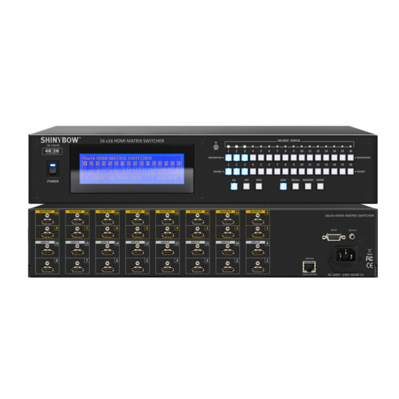
Page 5: Front Panel
FRONT PANEL FRONT PANEL 1. POWER ON SWITCH: The power switch turns the unit on and off. The LCM will illuminate blue to indicate the switcher is ON and receiving power. The switcher will remember the last setting during a power cycle. When power is removed and resorted, the last configuration will be evoked. - Page 6 FRONT PANEL FRONT PANEL 8. FUNCTION KEY - ALL Disables (mute) video on all destinations OR assign the same source to all destinations. Option 1 - Press ALL followed by OFF button. The display will show ”0” to indicate none of the destinations are assigned a video source.
- Page 7 FRONT PANEL FRONT PANEL 12. FUNCTION KEY - MEMORY The system can save up to 16 sets of switching routes, which are stored in local memory using Source keys 1 thru 16 or Destination buttons 1 thru 16 as the memory location. - Configure desired matrices .
-
Page 8: Back Panel
BACK PANEL BACK PANEL 1. DC POWER INLET: Power Jack: The switcher is fitted with a DC power plug input DC Jack - Inner OD Ø 2.1 mm (+) connector. Ensure that the used is of an approved type and is of Outside OD Ø... -
Page 9: Remote Control
REMOTE CONTROL Before making any connections observe the following: • Ensure the mains voltage supply matches the label on the supplied plug- Pack (+/- 10%). • Ensure that the power switch is OFF. • Ensure that all system grounds (earth) are connected to a common point. •... - Page 10 REMOTE PROTOCOL COMMANDS IR REMOTE CUSTOM AND DATA CODES (NEC Standard) HOW TO SETUP IR CODES : CUSTOM CODE : 32CD POWER ON : 32CD A15E LOCK : 32CD B54A POWER OFF : 32CD A25D RECALL : 32CD B24D ALL : 32CD B04F ENTER : 32CD B34C OFF : 32CD B14E MEMORY : 32CD B44B...
-
Page 11: Edid Functions
EDID FUNCTION EDID FUNCTION SETUP EDID Setup How to enter and exit 1. ENTER : After the switcher is powered on, the screen shows the main ENTER EXIT EDID EDID page. Press EDID to enter the EDID setup page. 2. SELECT : EDID mode selection will show on the top. DES is an abbreviation for destination buttons while SRC for source buttons. -
Page 12: Edid Function
EDID FUNCTION EDID function : 7x Embedded EDID Modes Mode 1. FSS (Fast Speed Start) Fast Speed Start mode shortens the startup time of the switcher. Selecting this mode does not force the EDID setup to be cancelled. Users may first select one EDID mode from mode 2 to 8, and then select mode 1 for fast speed start. - Page 13 EDID FUNCTION EDID FUNCTION : LEARNING Learning EDID Single Destination to Single Source EDID Destination 1 thru 16 Source 1 thru 16 Enter Copy the EDID of a single destination device and pass it to a single source. The source device will output video and audio according to the EDID of the destination.
-
Page 14: Troubleshooting
EDID FUNCTION COMPARISON TABLE Function Note Learning Let the source device(s) learn the EDID When a source devices has “learned” the EDID information of a destination Mode from a single source and output video device, the switcher will save that EDID into EPROM and the stored EDID and audio accordingly. -
Page 15: Ir Extender
IR EXTENDER 1. SB-100 IR 300M Receiver Switcher IR EXT. In Cable (3C) IR Receiver (SB-100) Distance: Max.300M IR PN#: SW-XXXX R oHS /95/E C INP UT R S -232 IR E XT. in DC 12V IR Rx RS - 232 IR EXT . - Page 16 RS-232 SERIAL INTERFACE RS-232 SERIAL INTERFACE CONNECT a PC or CONTROL SYSTEM. VERSION -2.0 COMPATIBLE RS-232 SERIAL CONNECT For a complete list of commands, please read the RS-232 Protocol Instruction Manual. Pin RS-232 Definition ------ Not used RS-232 PROTOCOL COMMANDS (RS-232 Control driver V2.0.1) The ShinybowUSA switcher can be controlled via the RS-232 serial control Transmitter port to allow for interfacing to a PC, or similar third party control system.
- Page 17 TYPICAL APPLICATION INSTALLING DIAGRAM Sample connection using IR transmitters (SB-101) and IR receiver (SB-100) with SB-6335T & SB-6335R to control a projector. NOTE: 1. IR Control Projector Over HDBaseT™ Extender: SB-6335 HDBaseT™ Transmitter SB-6335R HDBaseT™ Receiver 2. RS-232 Control 3. External IR Remote. 4.
- Page 18 TYPICAL APPLICATION INSTALLING DIAGRAM Example connection using IR transmitters (SB-101) and IR receivers (SB-100) with SB-6335T and SB-6335R to control a satellite receiver. NOTE: 1.IR Control Satellite Receiver Over HDBaseT™ CAT6/6a/7 extender from room: SB-6335 HDBaseT™ CAT5e/6/7 Transmitter SB-6335R HDBaseT™ CAT5e/6/7 Receiver 2.
-
Page 19: Limited Warranty
LIMITED WARRANTY PLEASE READ THE FOLLOWING TERMS AND CONDITIONS CAREFULLY BEFORE USING THIS HARDWARE, COMPONENTS AND SOFTWARE PROVIDED BY, THROUGH OR UNDER SHINYBOWUSA, INC (COLLECTIVELY, THE “PRODUCT”). By using installing or using the Product, you unconditionally signify your agreement to these Terms and Conditions. If you do not agree to these Terms and Conditions, do not use the Product and return the Product to SHINYBOWUSA, Inc. - Page 20 122 Rose Ln. Suite 303 | Frisco, Texas 75034 1-877-SHINY-USA 1-877-744-6987 1-972-377-2508 sales@shinybowusa.com www.shinybowusa.com...
Need help?
Do you have a question about the SB-5669K and is the answer not in the manual?
Questions and answers