Table of Contents
Advertisement
Advertisement
Table of Contents

Related Manuals for Gree GWC36LB-D1NNA2A/I


Summary of Contents for Gree GWC36LB-D1NNA2A/I
-
Page 4: Summary And Features
Summary and features Summary and features Indoor Unit GWC36LB-D1NNA2A/I GWH36LB-D1NNA2A/I Outdoor Unit GWC36LB-D1NNA2A/O GWH36LB-D1NNA2A/O Remote control window AUTO HEALTH BLOW HUMIDITY FILTER TURBO HOUR ON/OFF YB1F2 ON/OFF MODE BLOW TEMP TIMER TURBO SLEEP LIGHT... -
Page 5: Safety Precautions
Safety Precautions 1.Safety Precautions Important! or rubbish. The unit should be installed according to the instructions This air conditioning system meets strict safety and in order to minimize the risk of damage from earthquakes, operating standards. As the installer or service person, typhoons or strong winds. -
Page 6: Unit Specifications
Air Flow Volume(SH/H/M/L/SL) 1400/1300/1100/950/- Dehumidifying Volume 2.43 SEER Btu/w.h HSPF Btu/w.h Application Area 46-70 Model of indoor unit GWC36LB-D1NNA2A/I Fan Type Cross-flow Diameter Length(DXL) 108X522.7 Fan Motor Cooling Speed(SH/H/ML/SL) r/min 1450/1350/1200/1050/- Fan Motor Heating Speed(SH/H/ML/SL) r/min Output of Fan Motor Fan Motor RLA 0.46... - Page 7 Specifications Model of Outdoor Unit GWC36LB-D1NNA2A/O Compressor Manufacturer/Trademark Dalian SANYO Compressor Co.'Ltd. Compressor Model C-SB261H6A Compressor Oil SAY56T Compressor Type Scroll L.R.A. Compressor RLA 16.7 Compressor Power Input 3850 Overload Protector internal Throttling Method Capillary Operation Temp 16~30 Ambient Temp (Cooling) 18~45 Ambient Temp (Heating) Condenser Form...
- Page 8 Specifications Models GWH36LB-D1NNA2A Model GWH36LB-D1NNA2A Product Code CA16900060 Rated Voltage Rated Frequency Phases Power Supply Mode Outdoor Cooling Capacity 9700 Heating Capacity 10850 Cooling Power Input 4100 4300 Heating Power Input Cooling Power Current 18.6 Heating Power Current 19.5 Rated Input 5400 Rated Current 27.3...
- Page 9 Specifications Model of Outdoor Unit GWH36LB-D1NNA2A/O Compressor Manufacturer/Trademark Dalian SANYO Compressor Co.'Ltd. Compressor Model C-SB261H6A Compressor Oil SAY56T Compressor Type Scroll L.R.A. Compressor RLA 16.7 Compressor Power Input 3850 Overload Protector internal Throttling Method Capillary Operation Temp 16~30 Ambient Temp (Cooling) 18~45 Ambient Temp (Heating) -7~24...
-
Page 10: Capacity Variation Ratio According To Temperature
Specifications 2.2 CapacityVariation Ratio According toTemperature Cooling Heating Condition Condition Indoor:DB21.1℃ Indoor:DB26.7℃ WB19.4℃ Indoor air flow: Super High Indoor air flow: Super High Pipe length:7.5m Pipe length:7.5m 32 33 34 35 36 37 38 39 40 41 42 43 44 45 46 Outdoor temp. -
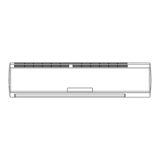
Page 11: Construction Views
Constrction views 3. Construction Views 3.1 Indoor Unit 1350... -
Page 12: Outdoor Unit
Constrction views 3.2 Outdoor Unit 1018... -
Page 13: Refrigerant System Diagram
Refrigerant System Diagram 4. Refrigerant System Diagram (1)Cooling Only Models INDOOR UNIT OUTDOOR UNIT GAS SIDE 3-WAY VALVE Muffler Di s charge HEAT EXCHANGE (EVAPORATOR) Suction Accumulator COMPRESSOR HEAT EXCHANGE (CONDENSER) LIQUID SIDE Capillary Strainer 2-WAY VALVE COOLING (2)Cooling & Heating Models INDOOR UNIT OUTDOOR UNIT GAS SIDE... -
Page 14: Schematic Diagram
Schematic Diagram 5. Schematic Diagram 5.1 Electrical data Symbol Color symbol Symbol Color symbol WHITE BROWN YELLOW BLUE BLACK PROTECTIVE EARTH YELLOW GREEN YEGN 5.2 Electrical wiring These circuit diagrams are subject to change without notice, please refer to the one supplied with the unit. Indoor Unit... - Page 15 Schematic Diagram Outdoor Unit Models GWC36LB-D1NTA2A/O EXHAUST TUBE ROOM TRANSFORMER TEMP. SENSOR TEMP. SENSOR TEMP. SENSOR N(1) N(4) POWER 1/L1 PTC2 CONTACTOR 2/T1 PTC1 LOW PRESSURE HIGH PRESSURE MOTOR SWITCH SWITCH COMP COMP. Models GWH36LB-D1NTA2A/O EXHAUST TUBE ROOM TRANSFORMER TEMP. SENSOR TEMP.
-
Page 16: Printed Circuit Board
Schematic Diagram 5.2 Printed Circuit Board TOP VIEW Connecting terminal of fan capacitor Live wire Protective tube Neutral wire Communication connecting terminal indoor outdoor units Connecting terminal super-high fan speed Connecting terminal for low fan speed Connecting terminal middle fan speed Connecting terminal for high fan speed Connecting... -
Page 17: Function And Control
Function and Control 6. Function and Control 6.1 Remote Control Operations Note: The remote controller is universal and it could be used for many units. Some buttons on this controller are not applicable to this unit. Be sure that there are no obstructions between receiver and remote controller; Do not drop or throw the remote controller;... - Page 18 Function and Control ON/OFF : Press this button to start the unit operation .Press this button again to stop the unit operation. MODE : Each time you press this button,a mode is selected in a sequence that goes from AUTO, , as the following: COOL,DRY, FAN, and HEAT COOL...
- Page 19 Function and Control HEALTH SAVE: Press HEALTH part of this button to turn on or off HEALTH function. (Not available for this mode) Pressing SAVE part of this button, is displayed and the unit goes into SAVE operation mode. Press SAVE part of the button again to cancel SAVE function .During SAVE operation, the tmperature and fan speed is not adjustable.
-
Page 20: Replacement Of Batteries
Function and Control SLEEP : Press this button to go into the SLEEP operation mode. Press it again to cancel. This function is available in COOL , HEAT (Only for models with heating function) or DRY mode to maintain the most comfortable temperature for you. LIGHT: Press LIGHT button to turn on the display's light and press this button again to turn off the display's light. -
Page 21: Description Of Each Control Operation
Function and Control 6.2 Description of Each Control Operation 1Temperature Parameters Indoor preset temperature (Tpreset) Indoor ambient temperature (Tamb.) 2 Basic functions Once the unit is energized, the compressor shall never be restarted except 3mins interval at least. For the first energization, if the unit is at off status before power failure, the compressor can be restarted without 3-min delay. - Page 22 Function and Control High Pressure Protection When it’s detected that the high pressure switch is open, the unit will turn to high pressure protection and all loads will be turned off. Meanwhile, all the buttons and remote control signal will be shielded; When the high pressure protection of compressor is released, the shielding of buttons and remote control signal will be released.
- Page 23 Function and Control Other protection Other protections are the same as those in cooling mode. (3)Heating mode (no for cooling only type) Heating conditions and process When Tamb. Tpreset+2 , the unit starts heating operation. In this case, the 4-way valve, compressor and outdoor fan operate simultaneously.
- Page 24 Function and Control 3 Other Control (1)Timer function General timer and clock timer functions are compatible by equipping different functions of remote controller. General Timer Timer ON can be set at unit OFF. If ON time setting is reached, the unit will start to operate according to previous setting status.
- Page 25 Function and Control O(0 ) (9) Display Operation and Mode Icons Upon energization, the unit will display all icons. Under standby state, running indicating mark is displayed in red. If the unit is started by remote controller, running indicating mark gives off light; meanwhile, the current setting running mode mark will be displayed(mode LED: cooling, heating and dry mode).
-
Page 26: Important Notices
Installation Manual 7. Installation Manual 7.1 Notices for installation Important Notices Important Notices The unit must only be installed by Authorised Service Center according to municipal or government regulations and in compliance with this manual . Before installating, please contact with local authorized maintenance center. If unit is not installed by the Authorised Service Center , the malfunction may not be solved due to discommodious contacts. -
Page 27: Earthing Requirements
Installation Manual Installation Location Selection of Outdoor Unit Installation Loctaion Selection of Outdoor Unit Select a location from which noise and outflow air emitted by unit will not inconvenience neighbors, animals and plants. Select a location where there is sufficient ventilation. Select a location where there is no obstructions which will cover the inlet and outlet vents The location should be able to withstand the full weight and vibration of the outdoor unit and permit safe installation. -
Page 28: Installation Dimension Diagram
Installation Manual 7.2 Installation Dimension Diagram Space to the ceiling Above Above Space to the wall Space to the wall Above Above Air outlet side Space to the floor Space to the obstruction Air inlet side Above Space to the wall Above Space to the wall Air outlet side... -
Page 29: Install Indoor Unit
Installation Manual 7.3 Install Indoor Unit Insta ll the re a r pa ne l 1.Always mount the rear panel horizontall y . As the water drainage pipe at the left, when adjusting the rear panel, this side should not be too high; the right side should be slightly high. 2. -
Page 30: Install The Indoor Unit
Installation Manual NOTE: When connecting the electric wire if the wire length is not enough, please contact with the authorized service shop to buy a exclusive electric wire that is long enough and the joint on the wire are not allowed. The electric wiring must be correctly connected, wrong connection may cause spare parts malfunction. -
Page 31: Install Outdoor Unit
Installation Manual 7.4 Install Outdoor Unit Electric Wiring 1. Disassemble handle of right side plate or front side plate of outdoor unit. 2. Remove the wire clamp and make the power connection cord and power cord matching with the indoor unit to the terminal board. 3. -
Page 32: Air Purging And Leakage Test
Installation Manual Air purging and leakage test 1. Connect charging hose of manifold valve to charge end of low pressure valve (both high/low pressure valves must be tightly shut). 2. Connect joint of charging hose to vacuum pump. 3. Fully open handle of Lo manifold valve. Liquid pipe 4. -
Page 33: Check After Installation And Test Operation
Installation Manual 7.5 Check After Installation and Test Operation Check after installation Items to be checked Possible malfunction The unit may drop, shake or emit noise. Has it been fixed firmly? It may cause insufficient cooling(heating) Have you done the refrigerant leakage test? capacity. - Page 34 Installation Manual 7.6 Installation and Maintenance of Healthy Filter Installation Instructions 1. Forcibly pull the panel for a specific angle from the two ends of the front panel according to the arrow direction. Then pull the air filter downwards to remove it. (See Fig.a) Fig.
-
Page 35: Exploded Views And Parts List
Exploded Views and Parts list 8. Exploded Views and Parts List 8.1 Indoor Unit... - Page 36 Exploded Views and Parts list Part Code Description GWC36LB-D1NNA2A/I Product Code CA169N0050 Receiver Window 22432164 Front Panel 20012490S Stand bar 24212120 Filter Sub-Assy 11122106 Front Case Sub-Assy 20012569 Upper Guide Louver 10512166 Lower guide louver 10512167 Axile Bush 10542704 Air Louver 2...
- Page 37 Exploded Views and Parts list Part Code Description GWH36LB-D1NNA2A/I Product Code CA169N0060 Receiver Window 22432164 Front Panel 20012490S Stand bar 24212120 Filter Sub-Assy 11122106 Front Case Sub-Assy 20012569 Upper Guide Louver 10512166 Lower guide louver 10512167 Axile Bush 10542704 Air Louver 2 10512169 Air Louver 1 10512168...
-
Page 38: Outdoor Unit
Exploded Views and Parts list 8.2 Outdoor Unit GWC36LB-D1NNA2A/O... - Page 39 Exploded Views and Parts list Part Code Description GWC36LB-D1NNA2A/O Product Code CA169W0050 Front Grill 22265401 Cabinet 01435103P Chassis Sub-assy 01205402 Compressor and fittings 00120131 Compressor Gasket 76710209 Rear Side Plate Sub-Assy 01305402 Valve Support Sub-Assy 01715402 Gas Valve Sub-Assy 07103401 Handle 26235253 Temperature Sensor...
- Page 40 Exploded Views and Parts list GWH36LB-D1NNA2A/O...
- Page 41 Exploded Views and Parts list Part Code Description GWH36LB-D1NNA2A/O Product Code CA169W0060 Front Grill 22265401 Cabinet 01435103P Drainage Connecter 06123401 Chassis Sub-assy 01205402 Drainage Plug 06813401 Compressor and fittings 00120131 Compressor Gasket 76710209 Rear Side Plate Sub-Assy 01305402 Valve Support Sub-Assy 01715402 Gas Valve Sub-Assy 07103401...
-
Page 42: Precautions Before Performing Inspection Or Repair
Troubleshooting 9. Troubleshooting 9.1 Precautions before Performing Inspection or Repair Be cautious during installation and maintenance. Do operation following the regulations to avoid electric shock and casualty or even death due to drop from high attitude. * Static maintenance is the maintenance during de-energization of the air conditioner. For static maintenance, make sure that the unit is de-energized and the plug is disconnected. - Page 43 Troubleshooting 1. The wiring terminal between outdoor condenser temperature sensor and controller is loosened or The unit will stop operation as it poorly contacted; reaches the temperature point. 2. There’s short circuit due to the trip-over of the parts Outdoor condenser During cooling and drying operation, on controller;...
-
Page 44: How To Check Simply The Main Part
Troubleshooting 9.4 How to Check simply the main part Malfunction of temperature sensor Malfunction diagnosis flowchart:... - Page 45 Troubleshooting Troubleshooting for high pressure protection (E1) Malfunction diagnosis flowchart: Start Whether the display panel and main board are Connect the display panel with the main board well Eliminate the malfunction connected tightly? Whether the OVC terminal on main board are Connect the OVC terminal on main board with the high connected well with high pressure switch on the Eliminate the malfunction...
- Page 46 Troubleshooting Troubleshooting for antifreezing protection (E2) Malfunction diagnosis flowchart: Start Solve the Eliminate the Poor air return in the indoor unit corresponding malfunction system problem Solve the Eliminate the The fan speed is abnormal corresponding malfunction speed problem Clean the Solve the Evaporator is dirty evaporator...
- Page 47 Troubleshooting Troubleshooting for low pressure protection of compressor (E3) Malfunction diagnosis flowchart: Start Check whether the Connect them Eliminate the main board and display board is correctly malfunction connected tightly? Check whether the Please confirm that Eliminate the LPP terminal on main board is connected well they are connected malfunction with the low pressure switch on the...
- Page 48 Troubleshooting Troubleshooting for high discharge temperature protection of compressor (E4) Malfunction diagnosis flowchart:...
- Page 49 Troubleshooting Troubleshooting for communication malfunction (E6) Malfunction diagnosis flowchart:...
-
Page 50: Appendix 1: Resistance Table Of Ambient Temperature Sensor For Indoor And Outdoor Units 15K
Troubleshooting Appendix 1: Resistance Table of Ambient Temperature Sensor for Indoor and Outdoor Units 15K Resistance Temp. Resistance Temp. Resistance Temp. Resistance Temp. -
Page 51: Appendix 2: Resistance Table Of Outdoor And Indoor Tube Temperature Sensors 20K
Troubleshooting Appendix 2: Resistance Table of Outdoor and Indoor Tube Temperature Sensors 20K Temp. Resistance Temp. Resistance Temp. Resistance Temp. Resistance 181.400 171.400 162.100 153.300 145.000 137.200 129.900 123.000 116.500... -
Page 52: Appendix 3: Resistance Table Of Outdoor Discharge Temperature Sensor 50K
Troubleshooting Appendix 3: Resistance Table of Outdoor Discharge Temperature Sensor 50K Temp. Temp. Temp. Temp. Resistance Resistance Resistance Resistance 853.500 799.800 750.000 703.800 4.334 660.800 620.800 580.600 548.900 516.600 Note: The above information is only for reference. -
Page 53: Removal Procedure Of Indoor Unit
Removal Procedure 10. Removal Procedure 10.1 Removal Procedure of Indoor Unit Warning Be sure to wait for a minium of 10 minutes after turning off power supplies before disassembly. Procedure Steps 1. Before disassembly Axonometric drawing for the complete indoor unit 2. - Page 54 Removal Procedure Steps Procedure 3. Remove display display Remove the two screws used for fixing the display and then remove the display. 4. Remove panel clasp Twist off the clasp at both sides of the panel slightly and then remove the panel. panel 5.
- Page 55 Removal Procedure 6. Remove electric box's top cover Remove the screws on the electric box's top cover screw Remove the electric box's top cover electric box's top cover screw 7. Remove front case Remove the 4 screw cover on the front case screw cover Twist off the 7 screws on front case front case...
- Page 56 Removal Procedure Steps Procedure 8. Remove earthing wire screw Remove the two earthing screws and then remove the earthing screw 9. Remove electric box cover screw Remove the 2 screws at the left side of the electric box screw Remove the 2 screws at the right side of the electric box electric box cover Remove the electric box cover...
- Page 57 Removal Procedure Steps Procedure 10. Remove temperature sensor tem perat ure senser Pull out the indoor tube tem perat ure senser 11. Remove electric box Pull out the 6 sockets on PCB screw Remove the two screws on electric box electric box Remove the electric box...
- Page 58 Removal Procedure Steps Procedure Remove main board Remove the screws on connection plate and then remove the connection wire. Take out the main board in electric box. Remove water tray water tray Lift up the water tray and then remove it. Remove the connecting tube of indoor and outdoor unit and electric wire Separate the connecting tube of indoor and...
- Page 59 Removal Procedure Steps Procedure Remove pipe-fixing plate Remove the two screws on the pipe-fixing plate at the back of indoor unit and then remove the pipe-fixing plate clasp plate screw Remove damper screw damper Remove the two screws on damper and then remove the damper Remove evaporator screw...
- Page 60 Removal Procedure Steps Procedure Remove the mounting plate of motor Remove the two screws on the mounting plate of motor with screwdriver and then remove the mounting plate of motor screw Remove cross flow blade and motor blade motor Remove the screws on cross flow blade and motor...
- Page 61 Removal Procedure Steps Procedure Remove the motor Separate the two cross flow blades Remove cushion rubber Remove the cushion rubber from the left cross flow blade cushion rubber Remove the cushion rubber from the chassis...
-
Page 62: Removal Procedure Of Outdoor Unit
Removal Procedure 10.2 Removal Procedure of Outdoor Unit GWC36LB-D1NNA2A/O Steps Procedure Before disassembly The complete outside over view of outdoor unit top panel Remove top panel Remove the screw used for fixing the top panel with screwdriver, lift up the top panel and then remove the top panel. - Page 63 Removal Procedure Procedure Steps Remove guard grille guard grille Remove the screws used for fixing the guard grille, pull out guard grille outward and then remove the guard grille Remove grille Remove the screws used for fixing the grille, loosen the clasp and then pull the grille outward grille Remove pa nel Remove the screws used for fixing the panel...
- Page 64 Removal Procedure Steps Procedure Remove right side plate right side plate Remove the screws used for fixing the right side plate and then pull the right side plate outwards. Remove electric box electric box Cut off the tieline, pull out the wiring terminal, remove all the connecting wires, remove the screws used for fixing the electric box, pull it upward and then remove the electric box.
- Page 65 Removal Procedure Steps Procedure 10. Remove motor Remove the screws used for fixing the motor, motor pull out the motor wires, pull it outward and then remove the motor. 11. Remove motor support motor support Remove the screws used for fixing the motor support, pull it upward and then remove the motor support 12.
- Page 66 Removal Procedure Steps Procedure 13. Remove gas and liquid separator gas and liquid separator Loosen the two screws used for fixing the gas and liquid separator, pull it upward and then remove the gas and liquid separator. 14. Remove compressor compressor Remove the nuts used for fixing the compressor with wrench, pull up the compressor upward and...
- Page 67 Removal Procedure Steps Procedure 16. Remove condenser and capillary Remove the screws on condenser, unsolder the spot weld (notice: before the soldering, release the refrigerant completely) between capillary and condenser, pull it outward and then remove the condenser and capillary. 17.
- Page 68 Removal Procedure GWH36LB-D1NNA2A/O Steps Procedure 1. Before disassembly The complete outside view drawing of outdoor unit Remove top panel top panel Remove the screws used for fixing the top panel with screwdriver, lift up the top panel and then remove the top panel. Remove front side plate Remove the screws used for fixing the front side plate, pull the front side plate forward and...
- Page 69 Removal Procedure Procedure Steps 4. Remove guard grille guard grille Remove the screws used for fixing the guard grille, pull the guard grille outward and then remove the guard grille Remove grille Remove the screw used for fixing the grille, loosen the clasp, pull out the grille outward and then remove the grille grille...
- Page 70 Removal Procedure Steps Procedure 7. Remove right side plate Remove the screw used for fixing the right side plate and then pull the right side plate outwards. right side plate 8. Remove electric box electric box Cut off the tieline, pull out the wiring terminal, remove all the connecting wires, remove the screws used for fixing the electric box, pull it upward and then remove the electric box...
- Page 71 Removal Procedure Steps Procedure 10.Remove motor Remove the screws used for fixing the motor, pull out the motor wire and pull it outward, and then remove the motor motor 11.Remove motor support motor support Remove the screws used for fixing the motor support, pull it upward and then remove the motor support 12.Remove four-way valve and air intake pipe...
- Page 72 Removal Procedure Procedure Steps 13. Remove gas and liquid separator gas and liquid separator Loosen the two screws used for fixing the gas and liquid separator, pull it upward and then remove the gas and liquid separator 14. Remove compressor compressor Remove the nuts used for fixing the compressor with wrench, pull the compressor upward to...
- Page 73 Removal Procedure Steps Procedure 16. Remove condenser and capillary Remove the screws used for fixing the condenser, unsolder the spot weld between capillary condenser (notice: before soldering, the refrigerant should be released completely), pull it outward and then remove the condenser and capillary Remove gas valve and valve support Remove the bolts used for fixing the gas valve...
Need help?
Do you have a question about the GWC36LB-D1NNA2A/I and is the answer not in the manual?
Questions and answers