
Subscribe to Our Youtube Channel
Related Manuals for Gree GWC30LB-D3DNA3G


Summary of Contents for Gree GWC30LB-D3DNA3G
- Page 1 Change for Life Service Manual Model: GWC30LB-D3DNA3G GWC30LB-D3DNA3H GWH30LB-D3DNA3G GWC36LB-D3DNA3G GWH36LB-D3DNA3G (Refrigerant R410A) GREE ELECTRIC APPLIANCES,INC.OF ZHUHAI...
-
Page 2: Table Of Contents
Service Manual Table of Contents Part : Technical Information ............... 1 1. Summary ........................1 ......................2 ......................2 ..................8 ............8 ........................9 ............. 9 3. Outline Dimension Diagram ..............10 3.1 Indoor Unit........................10 ........................10 4. Refrigerant System Diagram ..............11 5. - Page 3 Service Manual 9. Troubleshooting ....................34 ........34 ................43 .................59 10. Exploded View and Parts List ..............61 10.1 Indoor Unit........................61 .........................64 11. Removal Procedure ..................68 ................68 ................77 Appendix: ........................83 ............83 ..............83 Appendix 3: Pipe Expanding M ...................84 ............85 Table of contents...
-
Page 4: Part : Technical Information
Service Manual Part : Technical Information 1. Summary Indoor Unit: Outdoor Unit: Remote Controller:... - Page 5 Service Manual Model GWC30LB-D3DNA3G GWH30LB-D3DNA3G CB171010700 CB171010600 Rated Voltage Cooling Capacity(Min~Max) 28000 28000 Heating Capacity(Min~Max) 28400 2700 2700 2800 11.5 11.5 3900 4000 17.5 6.34 6.34 10.37 10.36 10.14 SEER SCOP Application Area 41.86-62.19 41.86-62.19 CB171N10700 CB171N10600 Pipe Diameter Indoor Unit...
- Page 6 Service Manual CB171W10700 CB171W10600 ZHUHAI LANDA COMPERSSOR ZHUHAI LANDA COMPERSSOR CO.LTD. CO.LTD. Compressor Model Compressor Oil RB68EP RB68EP Compressor Type Rotary Rotary Compressor RLA 13.45 13.45 2450 2450 1NT11L-6233 1NT11L-6233 Operation temp 61~86 61~86 Ambient temp (cooling) 5~115 5~115 -4~75 Pipe Diameter 0.45 0.45...
- Page 7 Service Manual Model GWC30LB-D3DNA3H CB171011800 Rated Voltage Cooling Capacity(Min~Max) 28000 Heating Capacity(Min~Max) 2700 11.5 3900 6.34 10.37 SEER SCOP Application Area 41.86-62.19 CB171N11800 Pipe Diameter Indoor Unit Swing Motor Model MP24BA 3.15 dB (A) dB (A) 41.9 51.8...
- Page 8 Service Manual CB171W11800 ZHUHAI LANDA COMPERSSOR CO.LTD. Compressor Model Compressor Oil RB68EP Compressor Type Rotary Compressor RLA 13.45 2450 1NT11L-6233 Operation temp 61~86 Ambient temp (cooling) 5~115 Pipe Diameter 0.45 2354 Climate Type Isolation IP24 PSIG PSIG dB (A) dB (A) 152.1 163.2 Refrigerant...
- Page 9 Service Manual Model GWC36LB-D3DNA3G(LC) GWH36LB-D3DNA3G(LCLH) CB171010900 CB171010800 Rated Voltage Cooling Capacity(Min~Max) 33600 33600 Heating Capacity(Min~Max) 34600 4100 4100 3800 16.5 4300 4300 8.20 8.20 9.11 SEER 18.00 18.00 SCOP 9.00 Application Area 55.01-83.72 55.01-83.72 CB171N10900 CB171N10800 Pipe Diameter Indoor Unit Swing Motor Model MP24BA MP24BA...
- Page 10 Service Manual CB171W10900 CB171W10800 MITSUBISHI ELECTRIC MITSUBISHI ELECTRIC (GUANGZHOU)COMPRESSOR (GUANGZHOU)COMPRESSOR CO. LTD CO. LTD Compressor Model Compressor Oil Compressor Type Rotary Rotary 67.00 67.00 Compressor RLA 13.50 13.50 3010 3010 Operation temp 61~86 61~86 Ambient temp (cooling) 0~109 0~109 -4~75 -4~75 Pipe Diameter 0.89...
-
Page 11: Operation Characteristic Curve
Service Manual 2.2 Operation Characteristic Curve Cooling Heating Condition Condition Indoor:DB 70°F Indoor:DB 80°F WB66°F Indoor air flow: Super High Indoor air flow: Super High Pipe length:24.6ft Pipe length:24.6ft Compressor Frequency(Hz) Compressor Frequency(Hz) 2.3 Capacity Variation Ratio According to Temperature Cooling Heating Conditions... -
Page 12: Noise Curve
Service Manual 2.4 Noise Curve Indoor side noise Outdoor side noise Compressor fre uency(H ) Indoor fan motor rating speed 2.5 Cooling and Heating Data Sheet in Rated Frequency Cooling: Rated cooling Compressor connecting indoor and Model (rps) Indoor P (MPa) 0.9~1.0 46.8 to 52.8 127 to 96.8... -
Page 13: Outline Dimension Diagram
Service Manual 3. Outline Dimension Diagram 3.1 Indoor Unit 53 1/7 13 7/9 29 3/8 2 3/4 2 3/4 11 3/5 3 1/2 3.2 Outdoor Unit... -
Page 14: Refrigerant System Diagram
Service Manual 4. Refrigerant System Diagram 30K: Cooling only model Outdoor unit Indoor unit as pipe side al e Di s charge Heat e changer Suction (e aporator) ccumlator Compressor Heat e changer i uid pipe (condenser) side al e lectron Capillary Strainer... - Page 15 Service Manual 36K: Cooling only model Outdoor unit Indoor unit Gas pipe side Valve Di s charge Heat exchanger (evaporator) Suction Accumlator Compressor Heat exchanger Liquid pipe (condenser) side Valve Electron Strainer expansion valve COOLING Cooling and heating model Indoor unit Outdoor unit Gas pipe side...
-
Page 16: Electrical Part
Service Manual 5. Electrical Part 5.1 Wiring Diagram Symbol Symbol Color Symbol Symbol Color Symbol Name Green Yellow Brown COMP Compressor YEGN Violet Orange... - Page 17 Service Manual...
-
Page 18: Pcb Printed Diagram
Service Manual 5.2 PCB Printed Diagram Indoor Unit Top view Name 2 2 2 Interface of fan motor Interface of display Interface of display interface interface Interface of wired controller terminal terminal Interface of BMS Interface of wired controller Interface of l Bottom view... - Page 19 Service Manual Outdoor Unit Top view Name Name Name compressor OVC-COMP 3 Terminal of temp sensor CN2 HEAT1-L Bottom view...
-
Page 20: Function And Control
Service Manual 6. Function and Control 6.1 Remote Controller Introduction Introduction for icons on display screen Set fan speed I feel Send signal Operation mode Cool mode Dry mode Set time Heat mode Sleep mode Up & down swing Temp. display type :Set temp. - Page 21 Service Manual 1. ON/OFF button 2. MODE button AUTO COOL HEAT Note: (60.8~86.0 3. FAN button Auto Caution: 4. SWING button no display Note: 5. TURBO button button (33.8...
- Page 22 Service Manual 7. SLEEP button 8. TEMP button no display r no di Note: 9. I FEEL button 10. LIGHT button 11. CLOCK button Note: 12. TIMER ON / TIMER OFF button Note:...
- Page 23 Service Manual Function introduction for combination buttons 1. Energy-saving function Note: 2. 8 heating function at 8 Note: TURBO 3. Child lock function 4. Temperature display switchover function Operation guide Replacement of batteries in remote controller signal sender battery reinstall are correct.
-
Page 24: Brief Description Of Modes And Functions
Service Manual 6.2 Brief Description of Modes and Functions 1. emperature Parameters Indoor preset temperature ( preset Indoor am ient temperature ( 2. Basic Functions Once energi ed in no case should the compressor e restarted within less than 3 minutes. In the situation that memory function is a aila le for the first energi ation if the compressor is at stop efore de-energi ation the compressor will e started w ithout a 3-minute lag if the compressor is in operation efore de-energi ation the compressor will e started with a 3-minute lag and once started the compressor will not e stopped within 6 minutes regardless of changes in room temperature... - Page 25 Service Manual Protection ② Protection is the same as that under the cooling mode. (3) Heating Mode Working conditions and process of heating ① If T Tpreset +3.6 , the unit enters heating mode, in which case the four-way valve, the compressor and the outdoor fan amb.
- Page 26 Service Manual ºF b.Under AUTO mode,if T +1.8 is detected,the unit will select to run under cooling mode,in which case implicit preset preset temperature is 77 ºF ; if T -1.8 ºF , the compressor will stop, the outdoor fan will stop with a time lag of 1 minute, and preset the indoor fan will run at preset speed;...
- Page 27 Service Manual Designation of sensors Faults he sensor is detected to e open-circuited or short-circuited for Indoor am ient temperature successi e 5 seconds he sensor is detected to e open-circuited or short-circuited for Indoor tu e temperature successi e 5 seconds he sensor is detected to e open-circuited or short-circuited for Outdoor am ient temperature successi e 30 seconds...
-
Page 28: Part : Installation And Maintenance
Service Manual Part : Installation and Maintenance 7. Notes for Installation and Maintenance Safety Precautions: 10. If the power cord or connection wire is not long enough, please get the specialized power cord or connection wire Important! from the manufacture or distributor. Prohibit prolong the wire by yourself. - Page 29 Service Manual Main Tools for Installation and Maintenance 1. Level meter, measuring tape 2. Screw driver 3. Impact drill, drill head, electric drill 4. Electroprobe 5. Universal meter 6. Torque wrench, open-end wrench, inner hexagon spanner 7. Electronic leakage detector 8.
-
Page 30: Installation
Service Manual 8. Installation 8.1 Installation Dimension Diagram Space to the wall Space to the wall At least 5 8/9 inch At least 5 8/9 inch Drainage pipe Installation and Maintenance... -
Page 31: Installation Procedures
Service Manual Installation procedures Start installation Preparation before installation Read the requirements select installation Prepare tools for electric connection location Select indoor unit Select outdoor unit installation location installation location Install the support of outdoor unit Install wall-mounting (select it according to the actual situation) frame, drill wall holes Connect pipes of indoor Fix outdoor unit... -
Page 32: Selection Of Installation Location
Service Manual 8.2 Installation Parts-checking 8.4 Electric Connection Requirement Name Name 1. Safety Precaution Wrapping tape Connection pipe Drainage pipe frame Connecting cable(power cord) remote controller conditioner. Wall pipe Air-conditioner Note: 8.3 Selection of Installation Location 1. Basic Requirement: 2. Grounding Requirement: 2. - Page 33 Service Manual 5. Connect the Pipe of Indoor Unit 3. Install Wall-mounting Frame Wall Wall Mark on the middle of it Gradienter Space Space Open-end to the to the wrench wall 6 wall 6 inch inch Union nut above above Pipe Pipe joint Union nut...
- Page 34 Service Manual 7. Connect Wire of Indoor Unit 8. Bind up Pipe Screw Panel Wiring cover Indoor and outdoor power cord Indoor unit pipe Liquid pipe Band Drain hose connection wire sleeve Drain hose Connection pipe Band Indoor power cord L1' S L2' G Note: white...
-
Page 35: Installation Of Outdoor Unit
Service Manual 8.6 Installation of Outdoor Unit 1. Fix the Support of Outdoor Unit(Select it according to ·Ibf) the actual installation situation) 11.10~14.75 20.12~29.50 33.19~40.56 44.24~47.94 expansion screws. 51.32~55.31 Note: 5. Connect Outdoor Electric Wire Handle screws are needed. green white black white... -
Page 36: Check After Installation And Test Operation
Service Manual 8.8 Check after Installation and Test Operation 1. Check after Installation installation. The drain hose can't be fluctuant The water outlet emit noise. can't be placed The drain hose in water can't be fluctuant The water outlet can't be fluctuant water dripping. -
Page 37: Troubleshooting
Service Manual 9. Troubleshooting 9.1 Flashing LED of Indoor/Outdoor Unit and Primary Judgement Display Method of Outdoor Display Method of Indoor Unit Unit Indicator has 3 kinds of Indicator Display (during display status and during Malfunction blinking, ON 0.5s and OFF Dual-8 A/C status Possible Causes... - Page 38 Service Manual Display Method of Outdoor Display Method of Indoor Unit Unit Indicator has 3 kinds of Indicator Display (during display status and during Malfunction blinking, ON 0.5s and OFF Dual-8 A/C status Possible Causes blinking, ON 0.5s and OFF Name 0.5s) Code...
- Page 39 Service Manual Display Method of Outdoor Display Method of Indoor Unit Unit Indicator has 3 kinds of Indicator Display (during display status and during Malfunction blinking, ON 0.5s and OFF Dual-8 A/C status Possible Causes blinking, ON 0.5s and OFF Name 0.5s) Code...
- Page 40 Service Manual Display Method of Outdoor Display Method of Indoor Unit Unit Indicator has 3 kinds of Indicator Display (during display status and during Malfunction blinking, ON 0.5s and OFF Dual-8 A/C status Possible Causes blinking, ON 0.5s and OFF Name 0.5s) Code...
- Page 41 Service Manual Display Method of Outdoor Display Method of Indoor Unit Unit Indicator has 3 kinds of Indicator Display (during display status and during Malfunction blinking, ON 0.5s and OFF Dual-8 A/C status Possible Causes blinking, ON 0.5s and OFF Name 0.5s) Code...
- Page 42 Service Manual Display Method of Outdoor Display Method of Indoor Unit Unit Indicator has 3 kinds of Indicator Display (during display status and during Malfunction blinking, ON 0.5s and OFF Dual-8 A/C status Possible Causes blinking, ON 0.5s and OFF Name 0.5s) Code...
- Page 43 Service Manual Display Method of Indoor Unit Display Method of Outdoor Unit Indicator Display (during Indicator has 3 kinds of display blinking, ON 0.5s and OFF status and during blinking, ON Dual-8 Malfunction A/C status Possible Causes 0.5s) 0.5s and OFF 0.5s Code Name Operation...
- Page 44 Service Manual Installation and Maintenance...
- Page 45 Service Manual Analysis or processing of some of the malfunction display: 1. Compressor discharge protection 2. Low voltage overcurrent protection 3. Communic ation malfun ction 4. Sensor open or short circuit 5. Compressor over load protection 6. System malfun ction 7.
-
Page 46: How To Check Simply The Main Part
Service Manual 9.2 How to Check Simply the Main Part Indoor unit 1. Malfunction of Temperature Sensor F1, F2 Main detection points: Start eliminated eliminated eliminated Installation and Maintenance... - Page 47 Service Manual 2.Malfunction of Blocked Protection of IDU Fan Motor H6 Start Turn the fan blades by hand under power-off condition Adjust the motor and blade Whether the fan blades assembly so that rotor can run can run smoothly? smoothly. Turn unit on to check whether the malfunction is...
- Page 48 Service Manual 3. Malfunction of Protection of Jumper Cap C5 Main detection points: Start eliminated eliminated eliminated Installation and Maintenance...
- Page 49 Service Manual 4. Malfunction of Overcurrent Protection E5 Main detection points: Start eliminated eliminated eliminated eliminated model eliminated eliminated opened completely) eliminated Installation and Maintenance...
- Page 50 Service Manual 5. Malfunction of Zero-crossing Inspection Circuit Malfunction of the IDU Fan Motor U8 Main detection points: Start U8 is still displayed Installation and Maintenance...
- Page 51 Service Manual 6.Malfunction of communication E6 Main detection points: Start Cut off power supply. Check if connection line of IDU and ODU and the wire inside electric box are correctly connected. Connect the line Correct connection? according to Malfunction eliminated? wiring diagram.
- Page 52 Service Manual Outdoor unit (1) Capacitor charge fault (Fault with outdoor unit) (AP1 below refers to the outdoor control panel) Main Check Points: Use AC voltmeter to check if the voltage between terminal L and N on the wiring board is within 210VAC~240VAC. If the reactor (L) is correctly connected? If the connection is loose or fallen? If the reactor (L) is damaged? Fault diagnosis process: Turn on the unit...
- Page 53 Service Manual (2) IPM Protection, Out-of-step Fault, Compressor Phase Overcurrent (AP1 below refers to the outdoor control panel) Main check points: If the connection between control panel AP1 and compressor COMP is secure? If loose? If the connection is in correct order? If the voltage input of the machine is within normal range? (Use AC voltmeter to measure the voltage between terminal L and N on the wiring board XT) If the compressor coil resistance is normal? If the insulation of compressor coil against the copper tube is in good condition?
- Page 54 Service Manual (3)High temperature and overload protection diagnosis (AP1 hereinafter refers to the control board of the outdoor unit) Mainly detect: Is outdoor ambient temperature in normal range? Are the outdoor and indoor fans operating normally? Is the heat dissipation environment inside and outside the unit is good? Fault diagnosis process: Overheat and high temperature protection...
- Page 55 Service Manual (4) Start-up failure (following AP1 for outdoor unit control board) Mainly detect: Whether the compressor wiring is connected correct? Is compressor broken? Is time for compressor stopping enough? Fault diagnosis process: Power on the unit Restart it up after Is stop time of the compressor 3 minutes longer than 3 minutes?
- Page 56 Service Manual (5) Out of step diagnosis for the compressor (AP1 hereinafter refers to the control board of the outdoor unit) Mainly detect: Whether the system pressure is too high? Whether the input voltage is too low? Fault diagnosis process: Out of step occurs in Out of step occurs once the operation...
- Page 57 Service Manual (6)Overload and air exhaust malfunction diagnosis (following AP1 for outdoor unit control board) Mainly detect: Wether the PMV is connected well or not? Is PMV damaged? Is refrigerant leaked? Fault diagnosis process: 20 minutes after the complete unit is powered off Is the terminal FA for the Connect the...
- Page 58 Service Manual (7)Power factor correct or (PFC) fault (a fault of outdoor unit) (AP1 hereinafter refers to the control board of the outdoor unit) Mainly detect: Check if the reactor (L) of the outdoor unit and the PFC capacitor are broken Fault diagnosis process: Start Check wiring of the...
- Page 59 Service Manual (8) Communication malfunction: (following AP1 for outdoor unit control board) Mainly detect: Is there any damage for the indoor unit mainboard communication circuit? Is communication circuit damaged? Detect the indoor and outdoor units connection wire and indoor and outdoor units inside wiring is connect well or not, if is there any damage? Fault diagnosis process: Start...
- Page 60 Service Manual (9) Communication malfunction:(following AP1 for outdoor unit control board) Mainly detect: Detect the indoor and outdoor units connection wire and indoor and outdoor units inside wiring is connect well or not, If is there any damage? Is there any damage for the indoor unit mainboard communication circuit? Is communication circuit damaged? The flow chart fir malfunction detect: Start Did the equipment operate...
- Page 61 Service Manual High-pressure protection Use pressure gauge to Measure if the pressure switch Replace the mainboard of measure if the pressure is is normal outdoor unit really high? Check if the operation mode of Set the correct operation Replace the pressure switch indoor unit is set properly? mode Check if the gas valve and...
-
Page 62: Troubleshooting For Normal Malfunction
Service Manual 9.3 Troubleshooting for Normal Malfunction 1. Air Conditioner Can't be Started up connected well. Wrong wire connection between or poor connection for wiring terminals reliably correctly once improper Replace batteries for remote controller Repair or replace remote controller 2. - Page 63 Service Manual 4. ODU Fan Motor Can't Operate Connect wires according to wiring diagram to connection diagram damaged fan capacitor. is bad and ODU compressor generates a lot of 5. Compressor Can't Operate Connect wires according to wiring diagram to connection diagram Capacity of compressor is...
-
Page 64: Exploded View And Parts List
Service Manual 10. Exploded View and Parts List 10.1 Indoor Unit Installation and Maintenance... - Page 65 Service Manual Part Code Description CB171N10700 CB171N11800 CB171N10600 22432164 22432164 22432164 20012490S 20012490S 20012490S Stand bar 24212120 24212120 24212120 11122106 11122106 11122106 20022159 20022159 20022159 10512166 10512166 10512166 10512167 10512167 10512167 10542704 10542704 10542704 10512169 10512169 10512169 10512168 10512168 10512168 Connecting Rod 10582086 10582086...
- Page 66 Service Manual Part Code Description CB171N10700 CB171N10600 22432164 22432164 20012490S 20012490S Stand bar 24212120 24212120 11122106 11122106 20022159 20022159 10512166 10512166 10512167 10512167 10542704 10542704 10512169 10512169 10512168 10512168 Connecting Rod 10582086 10582086 26112158 26112158 Water Tray 20182138 20182138 242520053 242520053 76712012 76712012...
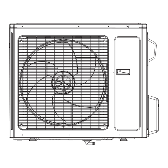
- Page 67 Service Manual 10.2 Outdoor Unit 10 11 12 Installation and Maintenance...
- Page 68 Service Manual Description CB171W10700 CB171W11800 CB171W10900 01473050 01473050 01473050 Cabinet 0143500401P 0143500401P 0143500401P 01303249P 01303249P 01303249P 10335014 10335014 10335014 0280310101P 0280310101P 0280302601P 76715022 76715022 76710207 00105051 00105051 00205275 03001300238 03001300238 03500600543 03001000246 03001000246 03001000246 0130504402P 0130504402P 0130504402P 0171501201P 0171501201P 0171501201P 07133157 07133157 07135054...
- Page 69 Service Manual 11 12 13 14 15 Installation and Maintenance...
- Page 70 Service Manual Part Code Description CB171W10600 CB171W10800 01473050 01473050 Cabinet 0143500401P 0143500401P 01303249P 01303249P 10335014 10335014 06813401 06813401 02803101P 02803026P Drainage Connecter 06123401 06123401 76715022 76710207 00105051 00205275 7651873209 7651873209 Magnet Coil 4300040029 4300040029 03123895 03123890 0130504402P 0130504402P 0171501201P 0171501201P 07133157 07135054 22245003...
-
Page 71: Removal Procedure
Service Manual 11. Removal Procedure Warning: Be sure to wait for a minimum of 20 minutes after turning off all power supplies and discharge the refrigerant 11.1 Removal Procedure of Indoor Unit completely before removal. Steps Procedure 1.Before disassembly of the unit Axonometric drawing for the complete unit. - Page 72 Service Manual Steps Procedure 3.Remove display display Remove 2 screws fixing display, and then remove the filter. 4.Remove panel clasp Pull the clasps at both sides slightly, and then remove the panel. panel 5.Remove horizontal louver Remove the axial bush on the horizontal louver, and then remove the horizontal louver.
- Page 73 Service Manual Steps Procedure 6.Remove top cover of electric box Remove screws fixing the top cover of electric box. screw Remove the top cover of electric box. top cover of electric box screw cap 7.Remove front case Remove the screw caps on front case. screw Remove screws connecting the front case.
- Page 74 Service Manual Steps Procedure 8.Remove earthing wire screw Remove earthing screws, and then remove the earthing wire. 9.Remove electric box cover clasp Loosen clasps at the left side of electric box. Loosen clasps on the right side of electric box. clasp electric box cover Remove electric box cover.
- Page 75 Service Manual Steps Procedure 10.Remove temperature sensor Pull out the indoor temperature sensor. temperature sensor 11.Remove electric box Pull out 6 sockets on PCB board. Pull out two screws on electric box. screw electric box Remove the electric box. Installation and Maintenance...
- Page 76 Service Manual Steps Procedure 12.Remove water tray water tray Pull the water tray upwards, and then remove the water tray. 13.Remove connection pipe between indoor and outdoor units Separate the connection pipe between indoor and outdoor units. connection position for indoor and outdoor units' connection pipe 14.Remove pipe-stopping plate Remove two screws on pipe-stopping plate for indoor unit, and then remove the pipe-stopping...
- Page 77 Service Manual Steps Procedure 16.Remove evaporator screw Remove screws between evaporator and bottom case. Turn over the indoor unit and adjust the pipe line to the position as shown by the broken line. Lift up the evaporator, and then remove the evaporator.
- Page 78 Service Manual Steps Procedure 18.Remove cross flow blade and motor blade motor Remove screws fixing cross flow blade and motor. Remove the motor sub-assy. Separate two cross flow blade. Installation and Maintenance...
- Page 79 Service Manual Steps Procedure 19.Remove cushion rubber Remove the cushion rubber on cross flow blade. cushion rubber Remove the cushion rubber from the base. Installation and Maintenance...
-
Page 80: Removal Procedure Of Outdoor Unit
Service Manual 11.2 Removal Procedure of Outdoor Unit Steps Procedure 1. Remove big handle,valve cover and top cover Remove the screw connecting the big handle and right side plate, and then remove the big handle. Remove the screw connecting the valve cover and right side plate, and then remove the valve cover. - Page 81 Service Manual Steps Procedure 4.Remove grille and panel Twist off the screws connecting the grille and panel, and then remove the grille. Twist off the screws connecting the panel, chassis and motor support with screwd-river, and then remove the panel. grille panel 5.Remove right side plate...
- Page 82 Service Manual Steps Procedure 7.Remove electric box electric box Twist off the screws on electric box, cut off the tieline with scissors or pliers, pull out the wiring terminal, pull it upwards to remove the electric box. Twist off the screws on electric box (fireproofing) electric box with screwdriver, and then remove the electric (fireproofing)
- Page 83 Service Manual Steps Procedure 9.Remove motor support Twist off the tapping screws fixingthe motor support, pull it upwardsand then remove the motor support. motor support 10.Remove isolation sheet Twist off the screws connecting isolation sheet and end plate of condenser and chassis, and then remove the isolation sheet.
- Page 84 Service Manual Steps Procedure 12.Remove gas valve and liquid valve Twist off the 2 bolts fixing the valve sub-assy. Unsolder the soldering joint between gas valve and air-return pipe and then remove the gas valve.(note: when unsoldering the soldering joint, wrap the gas valve with wet cloth completely to gas valve avoid the damage to valve, and release all...
- Page 85 Service Manual Steps Procedure 15.Remove left side plate Twist off the screws connecting the left side plate and chassis with screwdriver, and then remove the left side plate. left side plate 16.Remove chassis and condenser Pull it upwards to separate the chassis and condenser.
-
Page 86: Appendix
Service Manual Appendix: Appendix 1: Reference Sheet of Celsius and Fahrenheit Conversion formula for Fahrenheit degree and Celsius degree: Tf=Tcx1.8+32 Set temperature display display display 60.8 69.8 78.8 62.6 71.6 80.6 64.4 73.4 82.4 66.2 75.2 84.2 Ambient temperature display display display 55.4... -
Page 87: Appendix 3: Pipe Expanding M
Service Manual Appendix 3: Pipe Expanding Method Pipe Note: Pipe cutter Improper pipe expanding is the main cause of refrigerant leakage.Please expand the pipe according to the following steps: Leaning Uneven Burr Pipe Shaper Downwards Union pipe Pipe Hard mold Note: Expander Pipe... - Page 88 Service Manual Appendix 4: List of Resistance for Temperature Sensor Resistance Table of Ambient Temperature Sensor for Indoor and Outdoor Units(15K) Temp.( Temp.( Temp.( Temp.( -2.2 138.1 18.75 138.2 3.848 208.4 1.071 -0.4 128.6 69.8 17.93 3.711 210.2 1.039 121.6 71.6 17.14 141.8...
- Page 89 Service Manual Resistance Table of Tube Temperature Sensors for Indoor and Outdoor (20K) Temp.( Temp.( Temp.( Temp.( -2.2 181.4 25.01 138.2 5.13 208.4 1.427 -0.4 171.4 69.8 23.9 4.948 210.2 1.386 162.1 71.6 22.85 141.8 4.773 1.346 153.3 73.4 21.85 143.6 4.605 213.8...
- Page 90 Service Manual Resistance Table of Discharge Temperature Sensor for Outdoor(50K) Temp.( Temp.( Temp.( Temp.( -20.2 853.5 120.2 18.34 190.4 4.754 -18.4 799.8 51.8 93.42 17.65 192.2 4.609 -16.6 53.6 89.07 123.8 16.99 4.469 -14.8 703.8 55.4 84.95 125.6 16.36 195.8 4.334 660.8 57.2...
- Page 91 GREE ELECTRIC APPLIANCES,INC.OF ZHUHAI HONG KONG GREE ELECTRIC APPLIANCES SALES LIMITED...
Need help?
Do you have a question about the GWC30LB-D3DNA3G and is the answer not in the manual?
Questions and answers