Pro-Form CROSSWALK 590 LT User Manual
Hide thumbs
Also See for CROSSWALK 590 LT:
- User manual (33 pages) ,
- User manual (32 pages) ,
- User manual (32 pages)
Table of Contents
Advertisement
www.proform.com
USER'S MANUAL
Model No. PFTL99909.3
Serial No.
Write the serial number in the space
above for reference.
Serial
Number
Decal
QUESTIONS?
If you have questions, or if parts
are damaged or missing, DO NOT
CONTACT THE STORE; please
contact Customer Care.
IMPORTANT: Please register this
product (see the limited warranty
on the back cover of this manual)
before contacting Customer Care.
CALL TOLL-FREE:
1-888-533-1333
Mon.–Fri. 6 a.m.–6 p.m. MT
Sat. 8 a.m.–4 p.m. MT
ON THE WEB:
www.proformservice.com
CAUTION
Read all precautions and instruc-
tions in this manual before using
this equipment. Save this manual
for future reference.
Advertisement
Table of Contents

Related Manuals for Pro-Form CROSSWALK 590 LT


Summary of Contents for Pro-Form CROSSWALK 590 LT
- Page 1 www.proform.com USER’S MANUAL Model No. PFTL99909.3 Serial No. Write the serial number in the space above for reference. Serial Number Decal QUESTIONS? If you have questions, or if parts are damaged or missing, DO NOT CONTACT THE STORE; please contact Customer Care. IMPORTANT: Please register this product (see the limited warranty on the back cover of this manual)
-
Page 2: Table Of Contents
TABLE OF CONTENTS WARNING DECAL PLACEMENT ............. . .2 IMPORTANT PRECAUTIONS . -
Page 3: Important Precautions
IMPORTANT PRECAUTIONS WARNING: To reduce the risk of serious injury, read all important precautions and instructions in this manual and all warnings on your treadmill before using your treadmill. ICON assumes no responsibility for personal injury or property damage sustained by or through the use of this product. - Page 4 DANGER: 19. Never leave the treadmill unattended while it Always unplug the power is running. Always remove the key, unplug cord immediately after use, before clean- the power cord, and press the power switch ing the treadmill, and before performing the into the off position when the treadmill is not maintenance and adjustment procedures in use.
-
Page 5: Before You Begin
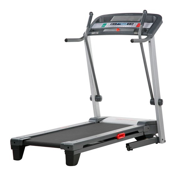
Thank you for selecting the new PROFORM reading this manual, please see the front cover of this ® CROSSWALK 590 LT treadmill. The CROSSWALK manual. To help us assist you, please note the product 590 LT treadmill offers a selection of features designed model number and serial number before contacting us. -
Page 6: Assembly
ASSEMBLY To hire an authorized service technician to assemble this product in your home, call 1-800-445-2480. Assembly requires two persons. Set the treadmill in a cleared area and remove all packing materials. Do not dispose of the packing materials until assembly is completed. Note: After shipping, there may be an oily sub- stance on the exterior of the treadmill or on the shipping carton. -
Page 7: With The Help Of A Second Person, Carefully Tip The
1. Make sure that the power cord is unplugged. With the help of a second person, carefully tip the treadmill onto its left side. Partially fold the Frame (57) so that the treadmill is more stable; do not fully fold the Frame yet. Remove and discard the two indicated screws (A) Hole and the shipping bracket (B). - Page 8 3. Remove the M10 Locknut (36), the M10 x 50mm Bolt (26), and the shipping bracket (C) from the Base (99). Attach a Wheel (95) with the Bolt and the Locknut that you just removed. Do not overtighten the Locknut; the Wheel must turn freely.
-
Page 9: With The Help Of A Second Person, Carefully Tip The
6. Press a Base Cap (91) into the Base (99). 7. With the help of a second person, carefully tip the treadmill onto its right side. Partially fold the Frame (57) so that the treadmill is more stable; do not fully fold the Frame yet. Remove and discard the two indicated screws (A) and the shipping bracket (B). - Page 10 8. Hold a Screw Spacer (98) inside the lower end of the Left Upright (79). Insert an M10 x 96mm Screw (7) with an M10 Star Washer (8) into the Left Upright and the Screw Spacer. Repeat this step with a second Screw Spacer (98), M10 x 96mm Screw (7), and M10 Star Washer (8).
- Page 11 11. Attach the Left Handrail (21) to the console assembly with three M4.2 x 19mm Screws (1). Remove the ties from the two M8 Cage Nuts (39). If necessary, press the Cage Nuts back into place. Console Assembly 12. Have a second person hold the console assembly near the Right Upright (80).
- Page 12 13. Partially tighten two M8 x 25mm Bolts (4) with two M8 Star Washers (9) into the Left Upright Console (79) and the Left Handrail (21); do not fully Assembly tighten the Bolts yet. Next, partially tighten two M8 x 25mm Bolts (4) with two M8 Star Washers (9) into the Right Upright (80) and the Right Handrail (100).
- Page 13 15. Insert the end of a Crosswalk Arm (82) into the hole in the top of a resistance mechanism. Make sure that the bend in the Crosswalk Arm is positioned as shown. Tighten an M4.2 x 19mm Screw (1) into the Bend resistance mechanism and Crosswalk Arm (82) from the direction shown.
-
Page 14: Operation And Adjustment
OPERATION AND ADJUSTMENT HOW TO CONNECT THE POWER CORD nominal 120-volt circuit capable of carrying 15 or more amps. To avoid overloading the circuit, do Use a Surge Suppressor not plug other electrical devices, except for low- power devices such as cell phone chargers, into Your treadmill, like other electronic equipment, can be the surge suppressor or into an outlet on the same circuit. - Page 15 CONSOLE DIAGRAM Clip FEATURES OF THE CONSOLE To turn on the power, see page 16. To use the man- ual mode, see page 16. To use a preset workout, see The treadmill console offers a selection of features page 18. To use the information mode, see page 19. designed to make your workouts more effective and IMPORTANT: If there is a sheet of plastic on the enjoyable.
-
Page 16: To Use Manual Mode
HOW TO TURN ON THE POWER 3. Start the walking belt. IMPORTANT: If the treadmill has been exposed to To start the walking belt, press the Start button, the cold temperatures, allow it to warm to room tem- Speed increase button, or one of the ten numbered perature before turning on the power. - Page 17 The lower left display To measure your can show the elapsed heart rate, stand time and the distance on the foot rails that you have walked or and place your run during the workout. hands on the Each time you change metal contacts—...
-
Page 18: To Use A Preset Workout
HOW TO USE A PRESET WORKOUT grammed for the next segment, the speed or in- cline setting will flash in the display to alert you. 1. Insert the key into the console. If you have selected a crosswalk workout, you will See HOW TO TURN ON THE POWER on page 16. - Page 19 THE INFORMATION MODE HOW TO USE THE CROSSWALK ARMS The console features an information mode that keeps As you walk on the treadmill, you can hold the hand- track of treadmill usage information and allows you to rails or use the crosswalk arms. To exercise your arms, select a unit of measurement for the console.
-
Page 20: How To Fold And Move The Treadmill
HOW TO FOLD AND MOVE THE TREADMILL HOW TO FOLD THE TREADMILL HOW TO MOVE THE TREADMILL To avoid damaging the treadmill, adjust the incline Before moving the treadmill, fold it as described at the to the lowest position before you fold the treadmill. left. -
Page 21: Troubleshooting
TROUBLESHOOTING Most treadmill problems can be solved by follow- d. If the treadmill still will not run, please see the front ing the simple steps below. Find the symptom that cover of this manual. applies, and follow the steps listed. If further assis- tance is needed, see the front cover of this manual. - Page 22 Remove the three M4.2 x 19mm Screws (1) and does not begin calibrating, press the Stop button, carefully pivot the Motor Hood (63) off. and then press the Incline increase or decrease button again. When the incline system is calibrated, remove the key from the console.
- Page 23 SYMPTOM: The walking belt is off-center or slips SYMPTOM: The crosswalk arms squeak during use when walked on a. (Note: Correcting this problem requires a small a. If the walking belt is off-center, first remove the amount of white marine grease, available at key and UNPLUG THE POWER CORD.
-
Page 24: Exercise Guidelines
EXERCISE GUIDELINES Burning Fat—To burn fat effectively, you must exer- WARNING: cise at a low intensity level for a sustained period of Before beginning this time. During the first few minutes of exercise, your or any exercise program, consult your physi- body uses carbohydrate calories for energy. - Page 25 SUGGESTED STRETCHES The correct form for several basic stretches is shown at the right. Move slowly as you stretch —never bounce. 1. Toe Touch Stretch Stand with your knees bent slightly and slowly bend forward from your hips. Allow your back and shoulders to relax as you reach down toward your toes as far as possible.
-
Page 26: Part List
PART LIST Model No. PFTL99909.3 R0112A Key No. Qty. Description Key No. Qty. Description M4.2 x 19mm Screw Walking Platform M4.2 x 25mm Tek Screw Drive Roller/Pulley 3/8" x 4 3/4" Screw Latch Cap M8 x 25mm Bolt Storage Latch 3/8"... - Page 27 Key No. Qty. Description Key No. Qty. Description Lift Motor Wire Drive Motor Bracket Handrail Cap 8" Cable Tie Console Base M4.2 x 10mm Screw Book Holder M8 Nut Fan Grill Foot Rail Decal Fan Housing/Fan – 12" Blue Wire, 2F 7 1/2"...
-
Page 28: Exploded Drawing
EXPLODED DRAWING A Model No. PFTL99909.3 R0112A... - Page 29 EXPLODED DRAWING B Model No. PFTL99909.3 R0112A...
- Page 30 EXPLODED DRAWING C Model No. PFTL99909.3 R0112A...
- Page 31 EXPLODED DRAWING D Model No. PFTL99909.3 R0112A...
-
Page 32: Ordering Replacement Parts
ORDERING REPLACEMENT PARTS To order replacement parts, please see the front cover of this manual. To help us assist you, be prepared to pro- vide the following information when contacting us: • the model number and serial number of the product (see the front cover of this manual) •...
Need help?
Do you have a question about the CROSSWALK 590 LT and is the answer not in the manual?
Questions and answers