Table of Contents
Advertisement
Advertisement
Table of Contents

Related Manuals for MSI MS-5148


Summary of Contents for MSI MS-5148
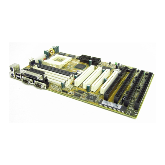
- Page 2 The PCI 430 TX system board is a high-performance personal computer system board based on a 3.3v version of the Pentium micrprocessor--the P54C and P55C, K6 and M2 with MMX microprocessor. The system board supports the Peripheral Component Interconnect (PCI) Local Bus Standard and provide four 32-bit PCI bus master slots.
-
Page 3: Cache Memory
Socket 7 supports Intel Pentium family -- P54C and P55C((MMX) 90MHz/100MHz/120Mhz/133MHz/150MHz/166MHz/200MHz/233MHz The Cyrix 6x86/M2 and AMD K5/K6 are also supported. Chip Set Intel 82430TX Cache Memory Supports Directed Map Organization,Write-Back cache policy. Supports 256K pipelined burst cache memory or 512K pipelined burst cache memory. - Page 4 Dimensions Standard ATX form factor 30cm(L) x 18.6cm(W) x 4 layer PCB Mounting 6 mounting holes...
-
Page 6: Cpu Installation Procedure
The 430 TX motherboard operates with Intel® P54C/P55C, Cyrix® 6x86/ M2 and AMD® 5K86/K6 processors. It could operates with 2.8V to 3.52V processors. The motherboard provides a 321-pin ZIF Socket 7 for easy CPU installation, a DIP switch (SW1) to set the proper speed for the CPU and a Jumper block (JV3 - JV7) for setting the CPU voltage. -
Page 7: Cpu Core Speed Derivation Procedure
2.1-2 CPU Core Speed Derivation Procedure 1. The 3 CPU clock frequencies that the system supports are 55MHz, 60MHz, 66MHz and 75MHz (To adjust SW1 pin 4, 5, and 6 ). See the following chart to set the different Host Clock Frequencies. Clock 55MHz 60MHz... - Page 8 2.1-3 CPU Voltage Setting: JV3 - JV7 The system board can autodetect whether the CPU is single or dual voltage. To adjust the Jumper setting of the CPU’s Vcore, just look at table below and set accordingly. JFAN INTEL FW82439TX BATT INTEL 2032...
- Page 9 2.1-4 CPU Speed and Voltage Setting: SW1 & JV3-JV7 To adjust the speed and voltage of the CPU, you must know the specifica- tion of your CPU (always ask the vendor for CPU specificaton) then look at Table 2.1 (Intel® P54C/P55C-MMX), Table 2.2 (Cyrix® 6x86/M2) and Table 2.3 (AMD®...
- Page 10 Table 2.1 Intel® P54C PENTIUM CPU CPU Voltage CPU Speed CPU Type JV3~JV7 VI/O Vcore 3.38 P54C-90 3.52 3.38 P54C-100 P54C-120 3.38 P54C-133 3.52 P54C-150 3.52 P54C-166 3.52 P54C-200 3.52 Intel® P55C PENTIUM (MMX) CPU P55C-166 P55C-200 3.3 P55C-233 Note: If you encounter a CPU with different Voltage, just go to page 2-3 and look for the proper voltage settings.
- Page 11 Table 2.2 Cyrix® 6x86 CPU Cyrix® 6x86 CPU uses P to rate the speed of there processor base on Intel® CPU core speed , for example P150+ (120MHz) has 150MHz core speed of Intel® but has 120MHz core speed in Cyrix®. Cyrix® 6x86 CPU should always uses a more powerful fan (ask vendor for proper cooling fan).
- Page 12 Table 2.3 AMD® 5K86 CPU AMD® 5K86 CPU uses PR to rate the speed of there processor base on Intel® CPU core speed , for example PR133+ (100MHz) has 133MHz core speed of Intel® but has 100MHz core speed in AMD® 5K86 CPU. CPU Voltage CPU Speed CPU Type...
- Page 13 2.1-5 CPU Fan Power Connector: JFAN This connector supports CPU cooling fan with +12V. It supports both two and three pin head connector. When connecting the wire to the connector, always take note that the red wire is the positive and should be connected to the +12V.
- Page 14 This jumper is for setting the Voltage of the Flash ROM BIOS. JFAN INTEL FW82439TX BATT INTEL 2032 FW82371AB JRMS1 BIOS JRMS2 JBAT J P 2 Voltage Setting +12V (default) Note: a. If you use Winbond , SST Flash ROM short 1-2 pin. b.
- Page 15 A battery must be used to retain the system board configuration in CMOS RAM. If you use the on-board battery you must short pins 1,2 of JBAT to keep the CMOS data. JFAN INTEL FW82439TX BATT INTEL 2032 FW82371AB JRMS1 BIOS JRMS2 JBAT...
- Page 16 Attach a power saving switch to JGS. When the switch is pressed, the system immediately goes into suspend mode. Press any key and the system wakes up. JGL can be connected with LED to monitor the JGS. JFAN INTEL FW82439TX BATT INTEL 2032...
-
Page 17: Memory Bank Configuration
2.5-1 Memory Bank Configuration The system board provides four 72-pin SIMMs (Single In-Line Memory Mod- ule) and two 168-pin DIMM(Double In-Line Memory) sockets, supports a maximum of 256MB of memory. You can use SIMM from 4MB, 8MB, 16MB, 32MB, 64MB or 128MB. And DIMM from 8MB, 16MB, 32MB, 64MB, 128MB, or 256MB. -
Page 18: Memory Installation Procedures
2.5-2 Memory Installation Procedures: A. How to install a SIMM Module Notched Single Sided SIMM Double Sided SIMM 1. The SIMM slot has a “Plastic Safety Tab” and the SIMM memory module has a “Notched End”, so the SIMM memory module can only fit in one direction. - Page 19 B. How to install a DIMM Module Single Sided DIMM Double Sided DIMM 1. The DIMM slot has a two key mark “VOLT and DRAM” , so the DIMM memory module can only fit in one direction. 2. Insert the DIMM memory module vertically into the DIMM slot then push it in.
- Page 20 B.1 DIMM Power Voltage Selector : JV1 JFAN INTEL FW82439TX BATT INTEL 2032 FW82371AB JRMS1 BIOS JRMS2 JBAT DIMM Voltage 3.3V SIMM Power Level : 5 Volts DIMM Power Level : 3.3V or 5V 2-15...
- Page 21 2.5-3 Memory Population Rule 1. Make sure that the SIMM banks are using the same type and equal size density memory. 2. To operate properly at least two 72-pin SIMM module must be installed in the same bank or one 168-pin DIMM module must be installed. 3.
- Page 22 Table 2.5-1 Minimum (upgradeable) and Maximum Memory Size for each configuration for SIMM DRAM MB/SIMM DRAM Address Size DRAM Density & Tech. Addressing Single Double Column pcs. Width Side(S) pcs. Side(D) 1Mx4 SYMM 4MBx8 8MBx16 1Mx16 SYMM 4MBx2 8MBx4 1Mx16 ASYM 4MBx2 8MBx4...
- Page 23 The Turbo LED, Hardware Reset, Key Lock, Power LED, Power Saving LED, Sleep Switch, Speaker and HDD LED all connected to the JFP connector block. JFAN INTEL FW82439TX BATT INTEL 2032 FW82371AB JRMS1 BIOS JRMS2 JBAT Speaker Power LED Keylock S l e e p P o w e r S a v i n g...
-
Page 24: Turbo Led
2.6-1 Turbo LED The Turbo LED are always ON. You can connect the Turbo LED from the system case to this pin. (See Figure 2.1) 2.6-2 Hardware Reset Reset switch are use to reboot the system rather than turning the power ON/ OFF, but avoid rebooting will the HDD LED is lit. -
Page 25: Pin Definition
The system board has two serial ports COMA and COMB. These two ports are 16550A high speed communication ports that send/receive 16 bytes FIFOs. You can attach a mouse or a modem cable directly into these connec- tors. 2 3 4 C O M A C O M B 6 7 8 9... - Page 26 The system board provides a connector for LPT. A parallel port is a stand- ard printer port that also supports Enhanced Parallel Port(EPP) and Extended capabilities Parallel Port(ECP). 13 12 11 10 9 8 7 6 5 4 3 2 1 25 24 23 22 21 20 19 18 17 16 15 14 JFAN INTEL...
- Page 27 The system board also provides a standard floppy disk connector FDD that supports 360K, 720K, 1.2M, 1.44M and 2.88M floppy disk types. You can attach a floppy disk cable directly to this connector. JFAN INTEL FW82439TX BATT INTEL 2032 FW82371AB JRMS1 BIOS JRMS2...
-
Page 28: Primary Ide Connector
The system board has a 32-bit Enhanced PCI IDE Controller that provide PIO mode 4 Ultra DMA33 speed. It has two HDD connectors IDE1 (primary) and IDE2 (secondary). You can connect up to four hard disk drives, CD-ROM, 120MB Floopy (reserved for future BIOS) and other devices to IDE1 and IDE2. - Page 29 2.12-1 ATX 20-pin Power Connector: JWR12 This connector support the power button on board soft power off and modem ring wakeup. you neeed to use the push button JRMS1 and JRMS2. 20........11 10........1 Power Connector ATX Power Connector Pin Description G N D G N D G N D PS_ON...
- Page 30 2.12-2 Power On/Off Switch: JRMS1/JRMS2 Connect to a 2-pin push button switch. Every time the switch is shorted by pushing it once, the power supply will change its status from OFF to ON. During ON stage push once and the system goes to sleep mode, push it more than 4 seconds will change its status from ON to OFF.
- Page 31 The system board provides a standard PS/2 style keyboard mini DIN connector for attaching a keyboard. You can plug a keyboard cable directly to this connector. It also provides a standard PS/2 style mouse mini DIN connector for attach- ing a PS/2 style mouse. You can plug a PS/2 style mouse directly into this connector.
- Page 32 The system board provide a USB(Universal Serial Bus) connector for attaching a keyboard, mose or etc. You can plug it directly to this connectro. Connector JFAN INTEL FW82439TX BATT INTEL 2032 FW82371AB JRMS1 BIOS JRMS2 JBAT 2-27...
- Page 33 The system board provides a 5-pin infrared connector(IR) for IR module. This connector is for optional wireless transmitting and receiving infrared module. You must configure the setting through BIOS setup. V C C N C R X G N D TX JFAN INTEL FW82439TX...
- Page 34 Award’s BIOS ROM has a built-in Setup program that allows users to modify the basic system configuration. This type of information is stored in battery -backed RAM (CMOS RAM), so that it retains the Setup information when the power is turned off.
-
Page 35: Main Menu
Power on the computer and press <Del> immediately will allow you to enter Setup. The other way to enter Setup is to power on the computer, when the below message appears briefly at the bottom of the screen during the POST (Power On Self Test), press <Del> key or simultaneously press <Ctrl>, <Alt>, and <Esc>... - Page 36 Once you enter Award BIOS CMOS Setup Utility, the Main Menu (Figure 1) will appear on the screen. The Main Menu allows you to select from ten setup functions and two exit choices. Use arrow keys to select among the items and press <Enter>...
- Page 37 Standard CMOS Setup This setup page includes all the items in a standard compatible BIOS. BIOS Features Setup This setup page includes all the items of Award special enhanced features. Chipset Features Setup This setup page includes all the items of chipset special features. Power Management Setup This category determines the power consumption for system after setting the specified items.
- Page 38 IDE HDD Auto Detection Automatically configure hard disk parameters. Save & Exit Setup Save CMOS value changes to CMOS and exit setup. Exit Without Save Abandon all CMOS value changes and exit setup.
- Page 39 The items in Standard CMOS Setup Menu are divided into 10 catego- ries. Each category includes no, one or more than one setup items. Use the arrow keys to highlight the item and then use the <PgUp> or <PgDn> keys to select the value you want in each item.
- Page 40 Date The date format is <day><month> <date> <year>. Day of the week, from Sun to Sat, determine. By BIOS, read only month The month Jan. through Dec. date The date from 1 to 31 can be keyed by numeric func- tion keys year...
- Page 41 If the controller of HDD interface is ESDI, the selection shall be “Type 1”. If the controller of HDD interface is SCSI, the selection shall be “None”. If the controller of HDD interface is CD-ROM, the selection shall be “None”. CYLS.
-
Page 42: Virus Warning
ROM PCI/ISA BIOS (2A59IM4A) BIOS FEATURES SETUP AWARD SOFTWARE, INC. Virus Warning Disabled Video BIOS Shadow :Enabled CPU Internal Cache Enabled C8000-CBFFF Shadow :Disabled External Cache Enabled CC000-CFFFF Shadow :Disabled Quick power on Self Test: Disabled D0000-D3FFF Shadow :Disabled Boot Sequence A,C,SCSI D4000-D7FFF Shadow :Disabled... -
Page 43: Cpu Internal Cache
Disabled (default) No warning message to appear when anything attempts to access the boot sector or hard disk partition table. Enabled Activates automatically when the system boots up causing a warning message to appear when anything attempts to access the boot sector of hard disk partition table. -
Page 44: Boot Sequence
Boot Sequence This category determines which drive the computer searches first for the disk operating system (i.e., DOS). The settings are A,C,SCSI/C,A,SCSI/ C,CD-ROM,A/CD-ROM,C,A/D,A,SCSI/E,A,SCSI/F,A,SCSI/SCSI,A,C/ SCSI,C,A/C only. Default value is A,C,SCSI. Swap Floppy Drive Switches the floppy disk drives between being designated as A and B. -
Page 45: Gate A20 Option
Boot Up System Speed It selects the default system speed - the speed that the system will run at immediately after power up. High (default) Set the speed to high Set the speed to low Gate A20 Option Normal The A20 signal is controlled by keyboard controller or chipset hardware. -
Page 46: Security Option
Typematic Delay Choose the length of delay from the time you press a key and the character repeating. (Units are mil-secs) Security Option This category allows you to limit access to the system and Setup, or just to Setup. System The system will not boot and access to Setup will be denied if the correct password is not entered at the prompt. -
Page 47: Video Bios Shadow
In this case, the PCI VGA controller should not respond to the Write, it should only snoop the data and permit the access to be forwarded to the ISA bus. The non-VGA ISA graphic controller can then snoop the data on the ISA bus. -
Page 48: Table Of Contents
The Chipset Features Setup option is used to change the values of the chipset registers. These registers control most of the system options in the computer. Choose the “CHIPSET FEATURES SETUP” from the Main Menu and the following screen will appear. ROM PCI/ISA BIOS(2A59IM4A) CMOS SETUP UTILITY CHIPSET FEATURES SETUP... -
Page 49: Auto Configuration
Auto Configuration Choosing Enabled (default) will automatically configure chipset features using default settings. Choose Disable to customize setup. DRAM Timing Sets the DRAM speed at 70ns (default) or 60ns. It will set the speed of the EDO/FP DRAM. DRAM Leadoff Timing To be able to change the setting, Auto configuration must be disable. -
Page 50: Dram Write Burst Timing
DRAM Write Burst Timing This option chooses the Write Burst Timing for accessing DRAM. See: DRAM Read Burst Option. Choose x222/x333/x444. Fast EDO Lead Off Under Autoconfig the BIOS will identify which type of DRAM is being used. Choose the setting accordingly. To customize use this option. Choose Enable or Disable. -
Page 51: Fast Ma To Ras# Delay :2 Clks
Fast MA to RAS# Delay The settings are 1 Clks or 2 Clks(default). During 1T One bus Clock is allowed, while 2T Two Bus Clock is allowed. MA address setup time to RAS assertion. This is also dependent on DRAM Timing. SDRAM (CAS Lat/RAS-to-CAS) The settings are 3/3 or 2/2. - Page 52 Memory Hole At 15M-16M Choosing Enabled will enable a memory hole in the DRAM space. The CPU cycle matching the enabled hole will be passed on to the PCI. PCI cycles matching an enabled hole are ignored. Disabled (default) will disable this function.
-
Page 53: Power Management
The Power Management Setup will appear on your screen like this: ROM PCI/ISA BIOS (2A59IM4A) POWER MANAGEMENT SETUP AWARD SOFTWARE, INC. ** Reload Global Timer Events ** Power Management : User Define IRQ [3-7,9-15],NMI : Enabled PM Control by APM : Yes Primary IDE 0 : Enabled... -
Page 54: Pm Control By Apm
Power Management Disable Global Power Management will be disabled. User Define Users can configure their own power management. Min Saving Pre-defined timer values are used such that all timers are in their MAX value. Max Saving Pre-defined timer values are used such that all timers MIN value. -
Page 55: Doze Mode
Video Off After The settings are N/A, Standby, Doze, or Suspend. This option is for choosing the setting in which the monitor will turn off. Always turn on. Doze During Doze Mode the monitor will turn off. Standby During Standby mode the monitor will turn off. Suspend During Suspend mode the monitor will turn off. -
Page 56: Suspend Mode
Suspend Mode Disable System will never enter SUSPEND mode. Defines the continuous idle time before the 1 Min/2 Min/ system entering SUSPEND mode. 4 Min/6 Min/ 8 Min/10 Min/ If any item defined in the options of “Power 20 Min/30 Min/ Down &... - Page 57 VGA Active Monitor During Enabled, if there’s no activities with the monitor screen the system will go into Power Saving Mode. And during Disabled, the system will go into Power Saving Mode, whether the monitor screen had activities or not. The settings are Disabled and Enabled. Soft-Off by PWR-BTTN The settings are Delay 4 sec or Instant-off.
- Page 58 Resume by Alarm This function is for setting date and time for your computer to boot up. During Disabled you can not use this function. And during Enabled choose the Date and Time Alarm: Date(of month) Alarm You can choose which month the system will boot up.
-
Page 59: Pnp Os Installed
You can manually configure the PCI Device’s IRQ. The following pages tell you the options of each item & describe the meanings of each options. ROM PCI/ISA BIOS (2A69HM4D) PNP/PCI CONFIGURATION SETUP AWARD SOFTWARE, INC. PCI IDE IRQ Map To : PCI-Auto PnP OS Installed Primary IDE INT#... -
Page 60: Resources Controlled By
Resources Controlled By By Choosing “Auto” the system BIOS will detect the system re- source and automatically assign the relative IRQ and DMA Channel for each peripheral. By Choosing “Manual”(default), the user will need to assign IRQ & DMA for add-on cards. Be sure that there is no conflict IRQ/DMA and I/O ports. - Page 61 IRQ-15 assigned to : PCI/ISA PnP DMA-0 assigned to : PCI/ISA PnP DMA-1 assigned to : PCI/ISA PnP DMA-3 assigned to : PCI/ISA PnP DMA-5 assigned to : PCI/ISA PnP DMA-6 assigned to : PCI/ISA PnP DMA-7 assigned to : PCI/ISA PnP The above settings will be shown on the screen only if “Manual”...
- Page 62 Assign IRQ for VGA Lets the user choose which IRQ to assign for VGA use. Used MEM base addr Lets the user choose the Legacy ISA addr. The settings are NA#, C800, CC00, D000, D400, D800 OR DC00. Used MEM Length Choose 8K, 16K, 32K, or 64K.
- Page 63 This Main Menu item loads the default system values. If the CMOS is corrupted the defaults are loaded automatically. Choose this item and the following message appears: “ Load Setup Defaults (Y / N) ? N “ To use the Setup defaults, change the prompt to “Y” and press < Enter > Note: The Setup defaults can be customized to increase performance.
-
Page 64: Ide Hdd Block Mode
ROM PCI/ISA BIOS (2A69HM4D) INTEGRATED PERIPHERALS AWARD SOFTWARE, INC. Onboard Parallel Mode :ECP/EPP IDE HDD Block Mode :Enabled ECP Mode Use DMA IDE Primary Master PIO :Auto Parallel Port EPP Type :EPP1 IDE Primary Slave PIO :Auto IDE Secondary Master PIO :Auto IDE Secondary Slave PIO :Auto IDE Primary Master UDMA... - Page 65 IDE Secondary Master PIO Auto/Mode0/Mode1-4 IDE Secondary Slave PIO Auto/Mode0/Mode1-4 For these 4 IDE option choose “Auto” to have the system BIOS auto detect the IDE HDD operation mode for PIO access. Note: Some IDE HDD can not operate at the responding HDD’s mode. When the user has selected “Auto”...
-
Page 66: Onboard Serial Port 1
On-Chip Secondary PCI IDE Enabled/Disabled The system provides for a On-Board On- Chipset PCI IDE controller that supports Dual Channel IDE (Primary and Secondary). A maximum of 4 IDE devices can be supported. If the user install the Off-Board PCI IDE controller (i.e. -
Page 67: Onboard Serial Port 2
Onboard Serial Port 2 Disabled/(3F8/IRQ4)/(2F8/IRQ3)/(3E8/IRQ4)/(2E8/IRQ3) The system has an On-board Super I/O chipset with 2 serial ports. The On- board serial ports can be selected as: Disabled 3F8/IRQ4 COMM1 uses IRQ4 2F8/IRQ3 COMM2 uses IRQ3 3E8/IRQ4 COMM3 uses IRQ4 2E8/IRQ3 COMM4 uses IRQ4 Note: Because the ISA Bus Interrupt accepts low to high edge trigger, the interrupt request line can not be shared by multiple sources. -
Page 68: Onboard Parallel Port
RxD , TxD Active Hi-Hi/Hi-Lo/ The user can choose between the preceding Lo-Hi/Lo-Lo RxD (Receive Data), TxD (Transmit Data) activity levels. Onboard Parallel Port Disabled/ There is a built-in parallel port on the on-board (3BCH/IRQ7)/ Super I/O chipset that provides Standard, ECP, (278H/IRQ5)/ and EPP features. -
Page 69: Usb Controller
will appear: “ECP Mode Use DMA” At this time the user can choose between DMA channels 3 or 1. The onboard parallel port is EPP Spec. compliant so after the user chooses the onboard parallel port with the EPP function and the following message will be displayed on the screen: “Parallel Port EPP Type.”... - Page 70 This Main Menu item lets you configure the system so that a pass- word is required each time the system boots or an attempt is made to enter the Setup program. Supervisor Password allows you to change all CMOS settings but the User Password setting doesn’t have this function. The way to set up the passwords for both Supervisor and User are as follow: 1.
- Page 71 You can use this utility to automatically detect the characteristics of most hard drives. When you enter this utility, the screen asks you to select a specific hard disk for Primary Master. If you accept a hard disk detected by the BIOS, you can enter “Y”...
Need help?
Do you have a question about the MS-5148 and is the answer not in the manual?
Questions and answers