Table of Contents
Advertisement
Quick Links
Chapter 1
INTRODUCTION
The Baby-AT VI14 mainboard is a high-performance personal computer
®
®
®
mainboard. This mainboard supports Intel
Pentium
processor/Pentium
TM
®
®
processor with MMX
technology, Cyrix
/IBM
6x86/6x86L/6x86MX/MII,
®
TM
AMD
K5/K6/K6-2, and IDT
Winchip processors. The mainboard also
supports four 32-bit PCI (Peripheral Component Interconnect) Local Bus
standard slots.
®
The mainboard uses the highly integrated VIA
598AT chipset to support
the AGP/PCI/ISA and Green standards, and to provide the Host/AGP bridge.
®
The VIA
586B chipset integrates all system control functions such as ACPI
(Advanced Configuration and Power Interface). The ACPI provides more
Energy Saving Features for the OSPM(OS Direct Power Management)
®
function. The VIA
586B chipset also improves the IDE transfer rate by
supporting Ultra DMA/33 IDE that transfer data at the rate of 33MB/s.
The mainboard uses the programmable synchronous DC/DC controller for
advanced processors. Synchronous operation allows the elimination of heat
sinks in many applications. The mainboard also provides 22 output voltage
from 1.80V to 3.50V in 100mV increments.
The mainboard also supports the System Hardware Monitor Controller as an
optional function. This function includes: CPU fan control, CPU tempera-
ture detect and protect & system voltage detect.
1-1
Advertisement
Table of Contents

Subscribe to Our Youtube Channel
Related Manuals for MSI MS-5184


Summary of Contents for MSI MS-5184
- Page 1 Chapter 1 INTRODUCTION The Baby-AT VI14 mainboard is a high-performance personal computer ® ® ® mainboard. This mainboard supports Intel Pentium processor/Pentium ® ® processor with MMX technology, Cyrix /IBM 6x86/6x86L/6x86MX/MII, ® K5/K6/K6-2, and IDT Winchip processors. The mainboard also supports four 32-bit PCI (Peripheral Component Interconnect) Local Bus standard slots.
- Page 2 Processor ® ® ® Socket 7 supports Intel Pentium processor/Pentium processor with technology. ® ® ® The Cyrix /IBM 6x86/6x86L/6x86MX/MII, AMD K5/K6/K6-2 and IDT Winchip processors are also supported. Chipset ® MVP3 chipset. Clock Generator 66/75/83.3/95/100/112/124/133MHz clocks are supported. Cache Memory Supports 1MB (Pipelined Burst SRAM) L2 Cache.
- Page 3 On-Board IDE An IDE controller provides IDE HDD/CD-ROM with PIO, Bus Master and Ultra DMA/33 operation modes. Can connect up to four IDE devices. On-Board Peripherals On-Board Peripherals include: - 1 floppy port supports 2 FDD with 360K, 720K, 1.2M, 1.44M and 2.88Mbytes.
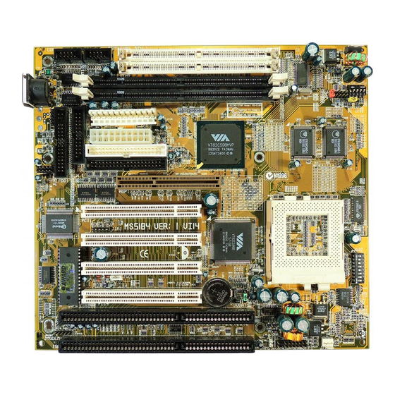
- Page 4 Keyboard JMODEM1 JMS1 JVSB1 FDD1 BIOS LPT1 JIR1 MVP3 BATT 586B JVBAT1 JRMS1 JFP1 Cache Cache JFAN1 MS-5184 Baby AT VI14 Mainboard...
-
Page 5: Hardware Installation
Chapter 2 Hardware Installation ® ® The Baby AT VI14 mainboard operates with Intel Pentium processor/ ® ® Pentium processor w/MMX technology, Cyrix /IBM 6x86/6x86L/ ® 6x86MX, AMD K5/K6/K6-2 and IDT Winchip processors. It could operate with 1.8V to 3.52V processors. The mainboard provides a 321-pin ZIF Socket 7 for easy CPU installation. - Page 6 2.1-2 CPU Core Speed Derivation Procedures 1. The DIP Switch SW1 is used to adjust the CPU, AGP, and PCI clock frequency. Clock 133.3 88.7 44.3 82.7 41.3 74.7 37.3 100.2 66.6 33.3 95.25 63.5 31.7 83.5 66.6 33.3 ON/OFF 37.5 ON/OFF 66.8...
- Page 7 2. The SW2 (6, 7, & 8) is used to set the Core/Bus (Fraction) ratio of the CPU. The actual core speed of the CPU is the Host Clock Frequency multiplied by the Core/Bus ratio. For example: CPU Clock 66MHz Core/Bus ratio then CPU core speed Host Clock x Core/Bus ratio...
- Page 8 2.1-3 Processor Voltage Setting a. Vcore Voltage Setting: SW2 The Dip Switch SW2 (1-5) is used to set the processor Vcore voltage setting. 1 2 3 4 5 Note: Always consult vendor for proper CPU specification, before setting the processor voltage (Vcore/Vio). Improper setting may damage the processor and other components.
- Page 9 Vcore 3.40 2.05 1.95 1.85...
- Page 10 b. Vi/o Voltage Setting: JP5 The Jumper Switch JP5 is used to set the processor Vi/o voltage setting. 3.3V 3.45V 3.6V 3.8V 4.0V...
- Page 11 2.1-4 CPU Speed and Voltage Setting: SW1, SW2 & JP5 To adjust the speed and voltage of the CPU, you must know the specifica- tions of your CPU (always ask the vendor for CPU specifications). Then ® ® refer to Table 2.1 (Intel processors), Table 2.2 (Cyrix processors) and ®...
- Page 12 ® Table 2.1 Intel processors ® ® Intel Pentium processors CPU Speed & Voltage Type VI/O Vcore 100MHz 1 2 3 4 5 6 7 8 133MHz 1 2 3 4 5 6 7 8 1 2 3 4 5 166MHz 1 2 3 4 5 6 7 8 200MHz...
- Page 13 ® Table 2.2 Cyrix processors ® Cyrix 6x86 processor uses PR to rate the speed of their processors based ® ® on Intel Pentium processor core speed. For example PR150 (120MHz) has ® ® 150MHz core speed of Intel Pentium processor but has 120MHz core ®...
- Page 14 ® Cyrix 6x86MX processors CPU Speed & Voltage Type VI/O Vcore PR166 (66x2) 1 2 3 4 5 1 2 3 4 5 6 7 8 PR200 (75x2) 1 2 3 4 5 6 7 8 PR233 1 2 3 4 5 (75x2.5) 1 2 3 4 5 6 7 8 ®...
- Page 15 ® Table 2.3 AMD processors ® K5 processor uses PR to rate the speed of their processors based on ® ® Intel Pentium processor core speed . For example PR133(100MHz) has ® ® 133MHz core speed of Intel Pentium processor but has 100MHz core ®...
- Page 16 ® K6 processors CPU Speed & Voltage Type VI/O Vcore PR166 1 2 3 4 5 6 7 8 1 2 3 4 5 PR200 1 2 3 4 5 1 2 3 4 5 6 7 8 PR233 1 2 3 4 5 1 2 3 4 5 6 7 8 PR266 1 2 3 4 5...
- Page 17 ® K6-2 processors CPU Speed & Voltage Type VI/O Vcore 300MHz 1 2 3 4 5 1 2 3 4 5 6 7 8 333MHz 1 2 3 4 5 6 7 8 1 2 3 4 5 350MHz 1 2 3 4 5 1 2 3 4 5 6 7 8 366MHz 1 2 3 4 5...
- Page 18 2.1-5 CPU Fan Connector: JFAN1 This connector supports fan with +12V. When connecting the wire to the connector, always take note that the red wire is the positive and should be connected to the +12V pin and the black one to GND. +12V SPEED N.C.
- Page 19 A battery must be used to retain the mainboard configuration in CMOS RAM. To retain the on-board battery you must always short pins 1-2 of JVBAT1. JVBAT1 (Default) Function JVBAT1 Keep Data Clear Data Note: You can clear CMOS by shorting 2-3 pin, while the system is off.
-
Page 20: Memory Bank Configuration
2.3-1 Memory Bank Configuration The mainboard provides two unbuffered 168-pin DIMM(Double In-Line Memory) or two 72-pin SIMM(Single In-Line Memory) sockets. It supports six memory banks for a maximum of 768MB memory. Each bank supports up to 128MB memory. You can use SIMM from 4MB, 8MB, 16MB, 32MB, 64MB to 128MB, and DIMM from 8, 16, 32, 64,128 to 256MB. -
Page 21: Memory Installation Procedures
2.3-2 Memory Installation Procedures: A. How to install SIMM Module Notched Single Sided SIMM Double Sided SIMM 1. The SIMM slot has a “Plastic Safety Tab” and the SIMM memory module has a “Notched End”, so the SIMM memory module can only fit in one direction. - Page 22 b. How to install a DIMM Module Single Sided DIMM Double Sided DIMM 1. The DIMM slot has two Notch Key called “VOLT and DRAM”, so the DIMM memory module can only fit in one direction. 2. Insert the DIMM memory module vertically into the DIMM slot. Then, push it in.
-
Page 23: Memory Population Rules
2.3-3 Memory Population Rules 1. Make sure that the SIMM banks are using the same type and equal size density memory. 2. To operate properly, at least two 72-pin SIMM module must be installed in the same bank or one 168-pin DIMM module must be installed. The system cannot operate with only one 72-pin SIMM module. - Page 24 The Power Switch, Reset Switch, Key Lock, Power LED, Speaker and HDD LED are all connected to the JFP1 connector block. Keylock Power Speaker Power Switch Reset Switch JFP1 2-20...
- Page 25 2.4-1 Power Switch Connect to a 2-pin push button switch. This switch has the same feature with JRMS1. 2.4-2 Reset Switch Reset switch is used to reboot the system rather than turning the power ON/ OFF. Avoid rebooting while the HDD LED is lit. You can connect the Reset switch from the system case to this pin.
- Page 26 The mainboard also provides a standard floppy disk connector FDD1 that supports 360K, 720K, 1.2M, 1.44M and 2.88M floppy disk types. You can attach a floppy disk cable directly to this connector. pin 1 FDD1 2-22...
- Page 27 The mainboard has a 32-bit Enhanced PCI IDE Controller that provides for two HDD connectors IDE1 (primary) and IDE2 (secondary). You can connect up to four hard disk drives, CD-ROM, 120MB Floppy (reserved for future BIOS) and other devices to IDE1 and IDE2. pin 1 pin 1 IDE1(primary IDE connector)
-
Page 28: Pin Description
This is a standard 12-pin AT-type or PS/2 type connector. Be sure to attach the connectors with the two black wires at the center. Power Connector PIN DEFINITION Description Description Power Good Ground +5V DC Ground +12V DC -5V DC -12V DC +5V DC Ground... - Page 29 This type of connector already supports the remote ON/OFF function. However, you need to connect the Remote Power On/OFF switch (JRMS1). Power Connector PIN DEFINITION SIGNAL SIGNAL 3.3V 3.3V -12V 3.3V PS_ON PW_OK 5V_SB 2-25...
- Page 30 The mainboard provides two serial port (COM 1 and COM 2) connectors. These two connectors are 16550A high speed communication ports that send/receive 16 bytes FIFOs. You can attach a mouse or a modem cable directly into these connectors. pin 1 pin 1 2-26...
- Page 31 The mainboard provides a connector for printer. A parallel port is a standard printer port that also supports Enhanced Parallel Port(EPP) and Extended capabilities Parallel Port(ECP). pin 1 LPT1 2-27...
- Page 32 The mainboard provides a 5-pin infrared connector(JIR1) for IR module. This connector is for optional wireless transmitting and receiving infrared module. If you want to use this function, you must configure the setting through BIOS setup. IRTX IRRX JIR1 2-28...
- Page 33 ® The mainboard provides a standard AT keyboard DIN connector for attaching a keyboard. You can plug a keyboard cable directly to this connector. Pin5 Pin1 Pin2 Pin4 Pin3 DATA ® Keyboard Connector 2-29...
- Page 34 ® The mainboard provides a 5-pin connector for PS/2 mouse cable. You can ® ® plug a PS/2 style mouse to PS/2 mouse cable. The connector location is shown below. JMS1 Pin 1 Pin 2 Pin 3 Pin 4 Pin 5 DATA 2-30...
- Page 35 Connect a USB cable to support USB device, such as keyboard and mouse. JUSB1 SIGNAL DESCRIPTION 1/10 -Data 0 Negative Data Channel 0 +Data 0 Positive Data Channel 0 Ground Ground +Data 1 Positive Data Channel 1 -Data 1 Negative Data Channel 1 USB Port Description 2-31...
- Page 36 The JWOL1 connector is for use with LAN add-on cards that supports Wake Up on LAN function. JWOL1 SIGNAL 5VSB MP_WAKEUP Note: LAN wake-up signal is active “high”. Note: To be able to use this function, you need a power supply that provide enough power for this feature.
- Page 37 The JMODEM1 connector is for use with Modem add-on card that supports the Modem Wake Up function. JMODEM1 SIGNAL MDM_WAKEUP 5VSB Note: Modem wake-up signal is active “low”. Note: To be able to use this function, you need a power supply that provide enough power for this feature.
-
Page 38: Award Bios Setup
® Chapter 3 AWARD BIOS SETUP ® Award BIOS ROM has a built-in Setup program that allows users to modify the basic system configuration. This type of information is stored in battery-backed RAM (CMOS RAM), so that it retains the Setup information when the power is turned off. -
Page 39: Status Page Setup Menu/Option Page Setup Menu
® Power on the computer and press <Del> immediately to allow you to enter Setup. The other way to enter Setup is to power on the computer. When the below message appears briefly at the bottom of the screen during the POST (Power On Self Test), press <Del>... -
Page 40: Bios Features Setup
® ® Once you enter Award BIOS CMOS Setup Utility, the Main Menu (Figure 1) will appear on the screen. The Main Menu allows you to select from eleven setup functions and two exit choices. Use arrow keys to select among the items and press <Enter>... - Page 41 ® Chipset Features Setup This setup page includes all the items of chipset special features. Power Management Setup This category determines the power consumption for system after setting the specified items. Default value is Disable. PCI Configuration Setup This category specifies the IRQ level for PCI and ISA devices. Load Setup Defaults Chipset defaults indicates the values required by the system for the maximum performance.
- Page 42 ® The items in Standard CMOS Setup Menu are divided into 10 catego- ries. Each category includes no, one or more than one setup items. Use the arrow keys to highlight the item and then use the <PgUp> or <PgDn> keys to select the value you want in each item.
-
Page 43: Primarymaster/Primaryslave Secondarymaster/Secondary Slave
® Date The date format is <day><month> <date> <year>. Day of the week, from Sun to Sat, determined by BIOS. Read-only. month The month from Jan. through Dec. date The date from 1 to 31 can be keyed by numeric function keys. - Page 44 ® If the controller of HDD interface is ESDI, the selection shall be “Type 1”. If the controller of HDD interface is SCSI, the selection shall be “None”. If the controller of HDD interface is CD-ROM, the selection shall be “None”.
-
Page 45: Anti-Virus Protection
® ROM PCI/ISA BIOS (2A5LEM4F) BIOS FEATURES SETUP AWARD SOFTWARE, INC. Anti-Virus Protection : Disabled Video BIOS Shadow :Enabled CPU Internal Cache : Enabled C8000-CBFFF Shadow :Disabled External Cache : Enabled CC000-CFFFF Shadow :Disabled D0000-D3FFF Shadow :Disabled Quick Power on Self Test : Disabled D4000-D7FFF Shadow :Disabled Boot Sequence... -
Page 46: Cpu Internal Cache
® Disabled No warning message to appear when anything attempts to access the boot sector or hard disk (default) partition table. Enabled Activates automatically when the system boots up causing a warning message to appear when anything attempts to access the boot sector of hard disk partition table. - Page 47 ® Boot Sequence This category determines which drive the computer searches first for the disk operating system (i.e., DOS). The settings are A,C,SCSI/C,A,SCSI/ C,CD-ROM,A/CD-ROM,C,A/D,A,SCSI/E,A,SCSI/F,A,SCSI/SCSI,A,C/ SCSI,C,A/C only, LS/ZIP,C. Default value is A, C, SCSI. Swap Floppy Drive Switches the floppy disk drives between being designated as A and B.
-
Page 48: Memory Parity/Ecc Check
® Memory Parity/ECC Check Set this option to Enabled, to use the Parity/ECC function. This is used with DIMM module. The default setting is Disabled. Security Option This category allows you to limit access to the system and Setup, or just to Setup. -
Page 49: Video Bios Shadow
® OS Selection for DRAM > 64MB ® Allows OS2 to be used with > 64 MB of DRAM. Settings are Non- OS/2 (default) and OS2. Set to OS/2 if using more than 64MB and running ® OS/2 Report No FDD For WIN 95 ®... - Page 50 ® The Chipset Features Setup option is used to change the values of the chipset registers. These registers control most of the system options in the computer. Choose the “CHIPSET FEATURES SETUP” from the Main Menu and the following screen will appear. ROM PCI/ISA BIOS(2A5LEM4F) CMOS SETUP UTILITY CHIPSET FEATURES SETUP...
- Page 51 ® Bank 0/1 DRAM Timing Bank 2/3 DRAM Timing Bank 4/5 DRAM Timing The DRAM timing is controlled by the DRAM Timing Registers. The Timings programmed into this register are dependent on the system design. Slower rates may be required in certain system designs to support loose layouts or slower memory.
- Page 52 ® System BIOS Cacheable Select Enabled allows caching of the system BIOS ROM at F000h- FFFFFh, resulting in better system performance. However, if any program writes to this memory area, a system error may result. Enabled BIOS access cached Disabled BIOS access not cached Memory Hole At 15Mb Addr In order to improve performance, certain space in memory can be...
-
Page 53: Spread Spectrum
® Spread Spectrum This item allows you to select the clock generator Spread Spectrum function. When overclocking the processor, always set this item to Disa- bled. The default is enabled. 3-16... -
Page 54: Power Management
® The Power Management Setup will appear on your screen like this: ROM PCI/ISA BIOS (2A5LEM4F) POWER MANAGEMENT SETUP AWARD SOFTWARE, INC. Primary INTR ACPI Function :Enabled IRQ3(COM2) :Primary Power Management :User Define IRQ4(COM1) :Primary PM Control by APM :Yes IRQ5(LPT2) :Primary Video Off Option... -
Page 55: Acpi Function
® ACPI Function During Enabled, this will support ACPI function. Power Management User Define Users can configure their own power management. Min Saving Pre-defined timer values are used such that all timers are in their MAX value. Max Saving Pre-defined timer values are used such that all timers are in their MIN value. -
Page 56: Soft-Off By Pwrbtn
® Soft-off by PWRBTN This field is for the soft-off function setting. When the board utilizes an ATX power supply, two types of settings are offered: Delay 4 sec. and Instant-off. When the setting is Delay 4 sec., users can power off the system by pressing POWER-ON button for 4 seconds. -
Page 57: Modem Ring Resume
® Suspend Mode Disable System will never enter SUSPEND mode. 10/20/30/40sec/ Defines the continuous idle time before the 1 Min/2 Min/ system enters SUSPEND mode. 4 Min/6 Min/ If any item defined in the options of “Power 8 Min/10 Min/ Down &... -
Page 58: Rtc Alarm Resume
® RTC Alarm Resume This function is for setting date and time for your computer to boot up. During Disabled, you cannot use this function. During Enabled, choose the Date and Time Alarm: Date(of month) Alarm You can choose which day of the month the system will boot up. -
Page 59: Pnp Os Installed
® You can manually configure the PCI Device’s IRQ. The following pages tell you the options of each item & describe the meanings of each options. ROM PCI/ISA BIOS (2A5LEM4F) PNP/PCI CONFIGURATION SETUP AWARD SOFTWARE, INC. PnP OS Installed CPU to PCI Write Buffer :Enabled Resources Controlled By :Manual... -
Page 60: Resources Controlled By
® Resources Controlled By By Choosing “Auto”, the system BIOS will detect the system resource and automatically assign the relative IRQ and DMA Channel for each peripheral. By Choosing “Manual”(default), the user will need to assign IRQ & DMA for add-on cards. Be sure that there is no conflict for IRQ/DMA and I/O ports. - Page 61 ® IRQ-15 assigned to : PCI/ISA PnP DMA-0 assigned to : PCI/ISA PnP DMA-1 assigned to : PCI/ISA PnP DMA-3 assigned to : PCI/ISA PnP DMA-5 assigned to : PCI/ISA PnP DMA-6 assigned to : PCI/ISA PnP DMA-7 assigned to : PCI/ISA PnP The above settings will be shown on the screen only if “Manual”...
-
Page 62: Pci Irq Activated By
® PCI#2 Access #1 Retry Enabled PCI#2 will be disconnected, if max retries are attempted without success. Disabled PCI#2 will not be disconnected until access is finish. PCI IRQ Activated By This sets the method by which the PCI Bus recognizes that an IRQ service is being requested by a device. - Page 63 ® This Main Menu item loads the default system values. If the CMOS is corrupted the defaults are loaded automatically. Choose this item and the following message appears: “ Load Setup Defaults (Y / N) ? N “ To use the Setup defaults, change the prompt to “Y” and press < Enter > Note: The Setup defaults can be customized to increase performance.
- Page 64 ® This Special Features Setup is used by System Hardware Monitor chipset. You can manually change the value of each option. ROM PCI/ISA BIOS (2A5LEM4F) INTEGRATED PERIPHERALS AWARD SOFTWARE, INC. ********* SYSTEM MONITOR ******** ******** POST SHOWING ******** CPU Fan Detected :Enabled CPU Fan RPM :6367...
- Page 65 ® CPU Fan RPM During Enabled, this will monitor the RPM of your CPU fan. System Temperature/CPU Temperature This will show the System and CPU temperature. CPU Critical Temp This option is for setting the critical temperature level for the proces- sor.
- Page 66 ® ROM PCI/ISA BIOS (2A5LEM4F) INTEGRATED PERIPHERALS AWARD SOFTWARE, INC. Onboard Parallel Mode :378/IRQ7 Onchip IDE First Channel :Enabled Parallel Port Mode :ECP/EPP Onchip IDE Second Channel:Enabled ECP Mode Use DMA IDE Prefetch Mode :Enabled EPP Mode Select :EPP1.9 IDE HDD Block Mode :Enabled IDE Primary Master PIO :Auto...
-
Page 67: Ide Hdd Block Mode
® IDE Prefetch Mode Enabled/Disabled IDE HDD Block Mode Enabled/Disabled Enabled allows the Block mode access for the IDE HDD. IDE Primary Master PIO Auto/Mode0/Mode1-4 IDE Primary Slave PIO Auto/Mode0/Mode1-4 IDE Secondary Master PIO Auto/Mode0/Mode1-4 IDE Secondary Slave PIO Auto/Mode0/Mode1-4 For these 4 IDE options, choose “Auto”... -
Page 68: Init Display First
® Init Display First This item allows you to determine whether AGP or PCI slot will show ® display first. This option is only used with Windows 98 support for multiple displays. Onboard FDD Controller Enabled/Disabled The system has an on-board Super I/O chip with a FDD controller that supports 2 FDDs for 360K/720K/1.2M/1.44M/ 2.8M. -
Page 69: Uart2 Mode
® UART2 Mode This item allow you to determine which Infra Red (IR) function of onboard I/O chip. If you choose IR function, the COM 2 will not function. Onboard Parallel Port Disabled There is a built-in parallel port on the on-board Super I/O chipset that pro- (3BCH/IRQ7)/ vides Standard, ECP, and EPP features. - Page 70 ® “ECP Mode Use DMA” At this time the user can choose between DMA chan- nels 3 or 1. The onboard parallel port is EPP Spec. compliant, so after the user chooses the onboard parallel port with the EPP function, the following message will be displayed on the screen: “EPP Mode Select.”...
- Page 71 ® This Main Menu item lets you configure the system so that a pass- word is required each time the system boots or an attempt is made to enter the Setup program. Supervisor Password allows you to change all CMOS settings but the User Password setting doesn’t have this function.
- Page 72 ® You can use this utility to automatically detect the characteristics of most hard drives. When you enter this utility, the screen asks you to select a specific hard disk for Primary Master. If you accept a hard disk detected by the BIOS, you can enter “Y”...
- Page 73 ® Chapter 4 ® BIOS USER’S GUIDE The system configuration information and chipset register information is stored in the CMOS RAM. This information is retained by a battery when the power is off. Enter the BIOS setup (if needed) to modify this information. The following pages will describe how to enter BIOS setup, and all about options.
-
Page 74: Enter Bios Setup
® 4.1 Enter BIOS Setup ® Enter the AMI setup Program’s Main Menu as follows: 1. Turn on or reboot the system. The following screen appears with a series of diagnostic check. AMIBIOS (C) 1998 American Megatrends Inc. A5I84MS VXXX XXXXXX Hit <DEL>... - Page 75 ® AMIBIOS HIFLEX SETUP UTILITIES - VERSION 1.07 (C) 1998 American Megatrends, Inc. All Rights Reserved Standard CMOS Setup Advanced CMOS Setup Advanced Chipset Setup Power Management Setup PCI/Plug and Play Setup Peripheral Setup Hardware Monitor Setup (optional) Auto-Detect Hard Disks Change User Password Change Supervisor Password Change Language Setting...
-
Page 76: Standard Cmos Setup
® 4.2 Standard CMOS Setup 1. Press <ENTER> on “Standard CMOS Setup” of the main menu screen . AMIBIOS SETUP - STANDARD CMOS SETUP (C)1998 American Megatrends,Inc.All Rights Reserved Date (mm/dd/yyyy): Fri March 20, 1998 Time (hh/mm/ss): 17:09:25 Floppy Drive A: 1.44 MB 3 1/2 Floppy Drive B: Not Installed... -
Page 77: Advanced Cmos Setup
® 4.3 Advanced CMOS Setup 1. Press <ENTER> on “Advanced CMOS Setup” of the main menu AMIBIOS SETUP - ADVANCED CMOS SETUP (C) 1998 American Megatrends, Inc. All Rights Reserved Quick Boot Disabled Available Options: Pri Master ARMD Emulated Auto Enabled Pri Slave ARMD Emulated Auto... -
Page 78: Quick Boot
® Description of the item on screen follows: Quick Boot ® Set this option to Enabled to permit AMI BIOS to boot within 5 seconds. This option replaces the old ABOVE 1 MB Memory Test option. The Optimal default setting is Enabled. The Fail-Safe default setting is Disabled. - Page 79 ® Initialize I2O Devices If set to Yes, BIOS will initialize I2O processors, I2O storage device, and provide INT13 support for I20 storage device. If set to No, BIOS will not initialize I2O processors and I2O storage device. Floppy Access Control This option sets the Floppy to Read-only or Read-Write.
-
Page 80: System Bios Cacheable
® ® Boot to OS/2 Set this option to Enabled to permit the BIOS to run properly, if OS/ ® is to be used with > 64MB of DRAM. The settings are Enabled or Disabled. The Optimal and Fail-safe default settings are Disabled. Internal Cache/External Cache ®... - Page 81 ® C800, 16k Shadow/CC00, 16k Shadow/D000, 16K Shadow/ D400, 16K Shadow/D800, 16K Shadow/DC00, 16K Shadow These options specify how the contents of the adaptor ROM named in the option title are handled. The ROM area that is not used by ISA adapter cards will be allocated to PCI adapter cards.
-
Page 82: Advanced Chipset Setup
® 4.4 Advanced Chipset Setup 1. Press <ENTER> on “Advanced Chipset Setup” of the main menu screen. AMIBIOS SETUP - ADVANCED CHIPSET SETUP (C) 1998 American Megatrends, Inc. All Rights Reserved Available Options: USB Function Disabled USB KB/Mouse Legacy Support Disabled Enabled Disabled... - Page 83 ® Description of the item on screen follows: USB Function Set this option to Enable or Disable the onchip USB controller. The default setting is Disabled. USB KB/Mouse Legacy Support Set this option to Enable or Disable USB Keyboard/Mouse. The default setting is Disabled Memory Hole This option allows the end user to specify the location of a memory...
- Page 84 ® ECC Mode Select Enabled or Disabled ECC (Error Correcting Code), according to the type of the installed DRAM. AGP Aperture Size This option determines the effective size of the graphics aperture used in the particular PAC configuration. The AGP aperture is memory- mapped, while graphics data structure can reside in a graphics aperture.
-
Page 85: Pci Delay Transaction
® PCI Delay Transaction This item allows you to Enable or Disable the PCI Delay Transaction. ClkGen for PCI Slot/DIMM This item allows the clock generator to auto-detect the interface of PCI/DIMM. If there’s no PCI/DIMM present, the clock will be shutdown. 4-13... -
Page 86: Power Management Setup
® 4.5 Power Management Setup 1. Press <ENTER> on “Power Management Setup” of the main menu screen. AMIBIOS SETUP - POWER MANAGEMENT SETUP (C) 1996 American Megatrends, Inc. All Rights Reserved Available Options: ACPI Aware OS Enabled Enabled Power Management / APM Disabled Disabled Green PC Monitor Power State... - Page 87 ® Description of the item on screen follows: ACPI Aware OS During Enabled, this will support ACPI function. Power Management/APM Set this option to Enabled to enable the chipset’s power management features and APM(Advanced Power Management). The settings are Enabled or Disabled. The Optimal and Fail-Safe default settings are Disa- bled.
- Page 88 ® Standby Time Out This option specifies the length of a period of system inactivity while in Full power on state. When this length of time expires, the computer enters Standby power state. The settings are Disabled, 1 min, 2 min, 4 min, 8 min, 10 min, 20 min, 30 min, 40 min, 50 min, or 60 min.
-
Page 89: Power Button Function
® Power Button Function During Suspend, if you push the switch once, the system goes into suspend mode and if you push it more than 4 seconds, the system will be turned off. During On/Off, the system will turn off once you push the switch. -
Page 90: Pci/Plug And Play Setup
® 4.6 PCI/Plug and Play Setup 1. Press <ENTER> on “PCI/Plug and Play Setup” of the main menu screen. AMIBIOS SETUP - PCI/PLUG AND PLAY SETUP (C) 1998 American Megatrends, Inc. All Rights Reserved Available Options: Plug and Play Aware O/S Enabled Clear NVRAM Enabled... -
Page 91: Clear Nvram
® Description of the item on screen follows: Plug and Play Aware O/S Set this option to Yes if the operating system in this computer is aware of and follows the Plug and Play specification. Currently, only ® Windows 95 or 98 is PnP-aware. The settings are Yes or No. The Optimal and Fail-Safe default settings No. -
Page 92: Offboard Pci Ide Card
® Offboard PCI IDE Card This option specifies if an offboard PCI IDE controller adapter card is installed in the computer. You must specify the PCI expansion slot on the mainboard where the offboard PCI IDE controller is installed. If an offboard PCI IDE controller is used, the onboard IDE controller is automatically ®... - Page 93 ® IRQ3/IRQ4/IRQ5/RQ7/IRQ9/IRQ10/IRQ11/IRQ14/IRQ15 These options specify the bus that the specified IRQ line is used on. These options allow you to reserve IRQs for legacy ISA adapter cards. ® These options determine if AMI BIOS should remove an IRQ from the pool of available IRQs passed to devices that are configurable by the system BIOS.
-
Page 94: Peripheral Setup
® 4.7 Peripheral Setup 1. Press <ENTER> on “Peripheral Setup” of the main menu screen. AMIBIOS SETUP - PERIPHERAL SETUP (C) 1998 American Megatrends, Inc. All Rights Reserved Available Options: OnBoard FDC Enabled Enabled OnBoard Serial Port1 3F8h/COM1 Disabled OnBoard Serial Port2 2F8h/COM2 OnBoard Parallel Port Parallel Port Mode... -
Page 95: Onboard Fdc
® Description of the item on screen follows: Onboard FDC Choose Auto, for the BIOS to automatically detect the device If the ISA add-on card has Onboard FDC to be set at Disabled FDC exist Enabled none FDC exist Choose Enabled, Enabling onboard FDC. Choose Disabled, Disabling onboard FDC. -
Page 96: Onboard Parallel Port
® Onboard Parallel Port Choose Auto, the BIOS automatically assigned onboard parallel port to the available parallel port or disabled. If the ISA add-on card has Onboard parallel port to be set as LPT1 LPT2 LPT3 PORT I/O:378H I/O:278H I/O:3BCH ASSIGNED ASSIGNED Disabled... -
Page 97: Parallel Port Irq
® Parallel Port IRQ If the onboard parallel mode is not on auto mode, the user can select the interrupt line for onboard parallel port. We suggest that the user select the interrupt for the onboard parallel port as shown below: Onboard parallel port set at Parallel Port IRQ LPT1(378H) - Page 98 ® 4.8 Hardware Monitor Setup (optional) The Hardware Monitor Setup is used to monitor the Current CPU temperature, CPU Fan speed, Chassis Fan Speed, Power fan speed, Vcore, etc. AMIBIOS SETUP - HARDWARE MONITOR SETUP (C) 1996 American Megatrends, Inc. All Rights Reserved Available Options: -=System Hardware Monitor=-...
Need help?
Do you have a question about the MS-5184 and is the answer not in the manual?
Questions and answers