Table of Contents
Advertisement
Quick Links
Chapter 1
INTRODUCTION
The MICRO ATX AL14 mainboard is a high-performance personal computer
®
®
®
mainboard. This mainboard supports Intel
Pentium
processor/Pentium
TM
®
®
processor with MMX
technology, AMD
K6/K6-2/K6-III, and Cyrix
6x86L/6x86MX/MII processors. This mainboard combines leading edge
®
®
AGP ATI
3D 128VR technology in graphics and Creative
ES1373 PCI
Enhanced technology in audio. The mainboard also supports three 32-bit
PCI (Peripheral Component Interconnect) Local Bus standard slots.
®
The mainboard uses the highly integrated Aladdin
5 chipset to support the
PCI/ISA and Green standards, and to provide the Host/AGP bridge. The
®
Aladdin
5 chipset integrates all system control functions such as ACPI
(Advanced Configuration and Power Interface). The ACPI provides more
Energy Saving Features for the OSPM(OS Direct Power Management)
®
function. The Aladdin
5 chipset also improves the IDE transfer rate by
supporting Ultra DMA/33 IDE that transfer data at the rate of 33MB/s.
1-1
Advertisement
Table of Contents

Subscribe to Our Youtube Channel
Related Manuals for MSI MS-5191


Summary of Contents for MSI MS-5191
- Page 1 Chapter 1 INTRODUCTION The MICRO ATX AL14 mainboard is a high-performance personal computer ® ® ® mainboard. This mainboard supports Intel Pentium processor/Pentium ® ® processor with MMX technology, AMD K6/K6-2/K6-III, and Cyrix 6x86L/6x86MX/MII processors. This mainboard combines leading edge ®...
-
Page 2: Cache Memory
® ® Socket 7 supports Intel Pentium processor with MMX technology. ® Cyrix 6x86L/6x86MX/MII are supported. ® K6/K6-2/K6-III processors are supported. Chipset ® Aladdin 5 M1541/M1543C chipset. FSB (Front Side Bus) 100/95/83.3/75/66MHz clocks are supported. Cache Memory Supports 512K or 1MB Pipelined Burst cache memory. Switching Regulator Provides CPU with voltage ranging from 1.3V to 3.5V Support VI/O 3.45 for AMD K6 300 processor... -
Page 3: On-Board Peripherals
Video ® 3D 128 VR - Running on AGP BUS. - Onboard 16MB SGRAM. - 3D Acceleration. Audio ® Creative ES1373 - Running on PCI BUS. - 64 Voice and AC3 Capable - Support Direct Sound and Direct Sound 3D - AC97’... - Page 4 Remote Control Meet ACPI specifications. Power ON/OFF switch connector on-board. Soft Power-Off. Support modem ring wake-up . Support alarm wake-up. Support LAN wake-up.
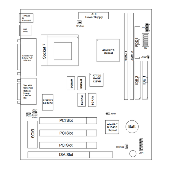
- Page 5 B:Serial Port/ VGA Port ® RAGE 128VR Top: Midi/ Game Port Bottom: Line-In Line-Out Creative ES1373 JCD1 JBAT1 JAUX1 JTAD1 PCI Slot Aladdin ® Batt M1543C chipset PCI Slot PCI Slot CHSFAN JFP1 ISA Slot MS-5191 MICRO ATX AL14 Mainboard...
-
Page 6: Hardware Installation
Chapter 2 HARDWARE INSTALLATION ® ® The MICRO ATX AL14 mainboard operates with Intel Pentium processor ® ® with MMX technology,AMD K6/K6-2/K6-III, and Cyrix 6x86L/ 6x86MX/MII processors. It could operate with 2.0V to 1.3V processors. The mainboard provides a 321-pin ZIF Socket 7 for easy CPU installation, a DIP switch (SW1) to set the proper speed for the CPU and (JV1) for setting the CPU voltage. -
Page 7: Cpu Core Speed Derivation Procedure
2.1-2 CPU Core Speed Derivation Procedure 1. The DIP Switch SW1 (4, 5, & 6) is used to adjust the CPU clock frequency. Clock 100MHz 95MHz 83MHz 75MHz 66MHz 60MHz 68MHz 2. The DIP Switch SW1 (1, 2, and 3) is used to set the Core/Bus (Fraction) ratio of the CPU. - Page 8 2.1-3 CPU Voltage Setting: JV1...
- Page 9 Other CPU Voltage Setting VI/O VCore 3.45 3.45 1.35 3.45 3.45 1.45 3.45 3.45 1.55 3.45 3.45 1.65 3.45 3.45 1.75 3.45 3.45 1.85 3.45 3.45 1.95 3.45 3.45 3.45 3.45 3.45 3.45 3.45 3.45 3.45 3.45 3.45 3.45 3.45 3.45 3.45 3.45...
- Page 10 2.1-4 CPU Speed and Voltage Setting: SW1 and JV1 To set the proper speed and voltage of the CPU, you must know the specifi- cations of your CPU (always ask the vendor for CPU specifications). ® ® Then refer to Table 2.1 (Intel Processor), Table 2.2 (Cyrix ®...
-
Page 11: Cpu Speed
® Table 2.1 Intel Processor ® ® a. Intel Pentium Processor with MMX Technology 166 MHz 200 MHz 233 MHz Note: In case, you encounter a CPU with different voltage, just go to Section 2.1-3 and look for the proper voltage settings. ®... -
Page 12: Cpu Voltage
® b. Cyrix 6x86MX Processor CPU Speed CPU Voltage Type VI/O Vcore PR200 (75 x 2) PR233 (66 x 3) (75 x 2.5) (83 x 2) PR266 (83 x 2.5) ® c. Cyrix MII processor CPU Voltage CPU Speed Type VI/O Vcore PR300 (66x3.5) - Page 13 ® Table 2.3 AMD Processor ® K6 processor uses PR to rate the speed of their processors based on ® ® Intel Pentium processor core speed . For example, PR133(100MHz) has ® ® 133MHz core speed of Intel Pentium processor but has 100MHz core ®...
- Page 14 CPU Voltage CPU Speed Type VI/O Vcore K6-2 450MHz K6-2 475MHz K6-3 400MHz K6-3 450MHz Note: In case, you encounter a CPU with different voltage, just go to Section 2.1-3 and look for the proper voltage settings.
- Page 15 2.1-6 Fan Power Connectors: CPUFAN & CHSFAN These connectors support system cooling fan with +12V. It supports three pin head connector. When connecting the wire to the connector, always take note that the red wire is the positive and should be connected to the +12V, the black wire is Ground and should be connected to GND.
-
Page 16: Memory Bank Configuration
2.2-1 Memory Bank Configuration The mainboard provides two 168-pin DIMM (Double In-Line Memory) sock- ets. It supports four memory banks for a maximum of 512MB memory. You can use DIMM from 8MB, 16MB, 32MB, 64MB, 128MB to 256MB. If you use 100 MHz CPU Bus Frequency, only PC100 DIMM Specs. -
Page 17: Memory Installation Procedure
2.2-2 Memory Installation Procedure: A. How to install DIMM Module Single Sided DIMM Double Sided DIMM 1. The DIMM slot has two keys marked “VOLT and DRAM” , so the DIMM memory module can only fit in one direction. 2. Insert the DIMM memory module vertically into the DIMM slot. Then, push it in. -
Page 18: Memory Population Rules
2.2-3 Memory Population Rules 1. This mainboard supports Table Free memory, so memory can be installed in DIMM1 or DIMM2 in any order. 2. Use only 3.3v unbuffered DIMM. 3. The DRAM addressing and the size supported by the mainboard is shown next page. - Page 19 Table 2.2-1 EDO DRAM Memory Addressing DRAM MB/DIMM Address Size DRAM DRAM Density & Addressing Tech. Single Double Column Width pcs. Side(S) pcs. Side(D) 1Mx16 SYMM 8MBx4 16MBx8 1Mx16 ASYM 8MBx4 16MBx8 2Mx8 ASYM 16MBx8 32MBx16 2Mx8 ASYM 16MBx8 32MBx16 4Mx4 SYMM 32MBx16 64MBx32...
- Page 20 The Power Switch, Reset Switch, Key Lock, Power LED, Speaker and HDD LED are all connected to the JFP1 connector block. Reset Switch Power Switch Speaker Power L E D L E D Keylock JFP1 2-15...
- Page 21 2.3-1 Power Switch Connect to a 2-pin push button switch. This switch has the same function with JRMS1. 2.3-2 Reset Switch Reset switch is used to reboot the system rather than turning the power ON/ OFF. Avoid rebooting while the HDD LED is lit. You can connect the Reset switch from the system case to this pin.
- Page 22 The mainboard also provides a standard floppy disk connector, FDD supports 360K, 720K, 1.2M, 1.44M and 2.88M floppy disk types. You can attach a floppy disk cable directly to this connector. 2-17...
- Page 23 The mainboard has a 32-bit Enhanced PCI IDE Controller that provides two HDD connectors IDE1 (Primary) and IDE2 (Secondary). You can connect up to four hard disk drives, CD-ROM, 120MB Floppy and other devices to IDE1 and IDE2. IDE1(Primary IDE Connector) The first hard disk should always be connected to IDE1.
- Page 24 This type of connector already supports the remote ON/OFF function. However, you need to connect the Remote Power On/OFF switch (JRMS1). Power Connector PIN DEFINITION SIGNAL SIGNAL 3.3V 3.3V -12V 3.3V PS_ON PW_OK 5V_SB Warning: Since the mainboard has the instant power on function, make sure that all components are installed properly before inserting the power connector to ensure that no damage will be done.
- Page 25 The mainboard has a 9-pin male DIN connector for serial port COM A. This port is a 16550A high speed communication port that send/receive 16 bytes FIFOs. You can attach a mouse or a modem cable directly into this connector. 1 2 3 4 6 7 8 9 COM A...
- Page 26 The mainboard provides a DB 15-pin connector to connect to a VGA monitor. Analog Video Display Connector(DB15-S) Signal Description Green Blue Not used Ground Ground Ground Ground Not used Ground Not used Horizontal Sync Vertical Sync 2-21...
- Page 27 The mainboard provides a 25 pin female centronic connector for LPT. A parallel port is a standard printer port that also supports Enhanced Parallel Port(EPP) and Extended Capabilities Parallel Port(ECP). See connector and pin definition below: Parallel Port (25-pin Female) L P T PIN DEFINITION SIGNAL...
- Page 28 ® The mainboard provides a standard PS/2 mouse mini DIN connector for ® ® attaching a PS/2 mouse. You can plug a PS/2 mouse directly into this connector. The connector location and pin definition are shown below: Pin5 Mouse Clock Pin6 Pin3 Pin4...
- Page 29 You can connect joystick or game pads to this connector. Joystick/MIDI Line Out is a connector for Speakers or Headphones. Line In is used for external CD player, Tape layer, or other audio devices. Mic is a connector for the microphones. Line Out Line In Mic 1/8”...
- Page 30 The mainboard provides a Universal Serial Bus root for attaching USB devices like: keyboard, mouse and other USB devices. You can plug the USB device directly to this connector. USB Port 2 1 2 3 4 USB Port 1 SIGNAL -Data0 +Data0 2-25...
- Page 31 A battery must be used to retain the mainboard configuration in CMOS RAM. If you use the on-board battery, you must short 1-2 pins of JBAT1 to keep the CMOS data. JBAT1 Note: You can clear CMOS by shorting 2-3 pin, while the system is off. Then, return to 1-2 pin position.
- Page 32 The mainboard provides CD Line-in connector to let you connect to the cable provided by the CD-ROM. Right Left JCD1 2-27...
- Page 33 Connect the audio cable provided by the CD, TV Tuner, or etc. into this connector. Right Left JAUX1 2-28...
- Page 34 This connector is for Internal Modem Card with internal voice connector. Phone Mono-out JTAD1 2-29...
- Page 35 ® Chapter 3 ® BIOS USER’S GUIDE The system configuration information and chipset register information is stored in the CMOS RAM. This information is retained by a battery when the power is off. Enter the BIOS setup (if needed) to modify this information. The following pages will describe how to enter BIOS setup, and all about options.
-
Page 36: Enter Bios Setup
® 3.1 Enter BIOS Setup ® Enter the AMI setup Program’s Main Menu as follows: 1. Turn on or reboot the system. The following screen appears with a series of diagnostic check. AMIBIOS (C) 1999 American Megatrends Inc. AR5191MS VXXX XXXXXX Main Processor: XXXXX Processor Clock: XXXMHz Hit <DEL>... - Page 37 ® AMIBIOS HIFLEX SETUP UTILITIES - VERSION 1.20 (C) 1998 American Megatrends, Inc. All Rights Reserved Standard CMOS Setup Advanced CMOS Setup Advanced Chipset Setup Power Management Setup Peripheral Setup Auto-Detect Hard Disks Change User Password Change Supervisor Password Auto Configuration with Optimal Settings Auto Configuration with Fail Safe Settings Save Settings and Exit Exit without Saving...
-
Page 38: Standard Cmos Setup
® 3.2 Standard CMOS Setup 1. Press <ENTER> on “Standard CMOS Setup” of the main menu screen . AMIBIOS SETUP - STANDARD CMOS SETUP (C)1998 American Megatrends,Inc.All Rights Reserved Date (mm/dd/yyyy): Fri Feb 27, 1998 Time (hh/mm/ss): 17:09:25 Floppy Drive A: 1.44 MB 3 1/2 Floppy Drive B: Not Installed... -
Page 39: Advanced Cmos Setup
® 3.3 Advanced CMOS Setup 1. Press <ENTER> on “Advanced CMOS Setup” of the main menu AMIBIOS SETUP - ADVANCED CMOS SETUP (C) 1998 American Megatrends, Inc. All Rights Reserved 1st Boot Device FLOPPY Available Options: 2nd Boot Device IDE-0 Disabled 3rd Boot Device LS120/ZIP... -
Page 40: Floppy Drive Swap
® Description of the item on screen follows: 1st Boot Device/2nd Boot Device/3rd Boot Device/4th Boot Device This option sets the sequence of boot drives. The settings are: IDE0 The system will boot from the first HDD. IDE1 The system will boot from the Second HDD. IDE2 The system will boot from the Third HDD. -
Page 41: Password Check
® Floppy Access Control This option sets the Floppy to Read-only or Normal. The default value is Normal. Typematic Control Key strokes repeat at a rate determined by the keyboard controller. When in normal mode, the typematic rate and typematic delay can be selected. -
Page 42: Advanced Chipset Setup
® 3.4 Advanced Chipset Setup 1. Press <ENTER> on “Advanced Chipset Setup” of the main menu screen. AMIBIOS SETUP - ADVANCED CHIPSET SETUP (C) 1998 American Megatrends, Inc. All Rights Reserved Available Options: USB Function Enabled USB Legacy Support Disabled Disabled Enabled DRAM Timing... - Page 43 ® Description of the item on screen are as follows: USB Function Set this option to Enable or Disable the on-chip USB controller. The Optional and Fail-Safe default setting is Enabled. USB Keyboard Legacy Support Set this option to Enable or Disable USB keyboard/mouse. The Optional and Fail-Safe default settings are Disabled.
- Page 44 ® Primary Frame Buffer The processor provides a write-combining with buffering strategy for write operation. This is useful for frame buffering. Writing to USWC memory can be buffered and combined in the processor’s write-combining buffer (WCB). The WCBs are viewed as a special purpose outgoing write buffers, rather than a cache.
- Page 45 ® Delay Transaction During Enabled, the chipset delay transaction mechanism is enabled when the chipset is the target of a PCI transaction. A read cycle from Host to PCI is immediately retrieved due to any pending PCI to DRAM cycle. During Disabled, a read cycle from the Host to PCI is waited until time-out due to any pending PCI to DRAM cycle.
-
Page 46: Power Management Setup
® 3.5 Power Management Setup 1. Press <ENTER> on “Power Management Setup” of the main menu screen. AMIBIOS SETUP - POWER MANAGEMENT SETUP (C) 1998 American Megatrends, Inc. All Rights Reserved Available Options: Power Management / APM Enabled Green Monitor Power State Disabled Enabled Video Power Down Mode... - Page 47 ® Description of the item on screen are as follows: Power Management/APM Set this option to Enabled to enable the power management features and APM(Advanced Power Management). The settings are Enabled, Inst- On(instant-on) or Disabled. The Optimal and Fail-Safe default settings are Disabled.
- Page 48 ® Suspend Time Out This option specifies the length of a period system inactivity while in Standby state. When this length of time expires, the computer enters Suspend power state. The settings are Disabled, 1 min, 2 min, 3 min, 4 min, 5 min, 6 min, 7 min, 8 min, 9 min, 10 min, 11 min, 12 min, 13 min, 14 min or 15 min.
-
Page 49: Peripheral Setup
® 3.6 Peripheral Setup 1. Press <ENTER> on “Peripheral Setup” of the main menu screen. AMIBIOS SETUP - PERIPHERAL SETUP (C) 1998 American Megatrends, Inc. All Rights Reserved OnBoard FDC Enabled Available Options: OnBoard Serial Port1 3F8/COM1 Enabled Onboard Serial Port2 2F8/COM2 Disabled Onboard Serial Port3... -
Page 50: Onboard Fdc
® Description of the item on screen follows: Onboard FDC Choose Auto, for the BIOS to automatically detect the device. If the ISA add-on card has Onboard FDC to be set at Disabled FDC exist Enabled none FDC exist Choose Enabled, Enabling onboard FDC. Choose Disabled, Disabling onboard FDC. -
Page 51: Onboard Parallel Port
® Onboard Parallel Port Choose Auto, for the BIOS to automatically assign the onboard parallel port to the available parallel port or disabled. If the ISA add-on card has Onboard parallel port to be set as LPT1 LPT2 LPT3 PORT I/O:378H I/O:278H I/O:3BCH... - Page 52 ® Parallel Port IRQ If the onboard parallel mode is not on auto mode, the user can select the interrupt line for onboard parallel port. We suggest that the user select the interrupt for the onboard parallel port as shown below: Onboard parallel port set at Parallel Port IRQ LPT1(378H)
-
Page 53: Ide Driver
Chapter 4 ® IDE DRIVER The on-chip IDE controller supports two separate IDE controllers for up to 4 IDE devices providing an interface for IDE hard disks and CD-ROMS. The Ultra DMA specification (which supports the 33M bytes per second transfer rate) has been implemented in this IDE controller. - Page 54 ® 2.1 Windows 95/98 2.1-1 ALi IDE Driver Installation Procedure: Step 1: Click on “ALi IDE Driver” icon. Step 2: This will show an ALi IDE Driver installation menu. Step 3: Click on “Next”. Step 4: Click on “Next” to install ALi PCI Bus Master IDE Driver. Step 5: This will copy the ALi IDE driver into the hard drive.
-
Page 55: System Requirements
Chapter 5 ® RAGE PRO TURBO VGA DRIVER ® The ATI RAGE PRO TURBO is a highly integrated graphics controller. Incorporated within this single chip are the 2D, 3D, and video accelerators, palette DAC, and dual-clock synthesizer. This multi-function integrated controller delivers TV-quality scaled video optimized for MPEG playback, industry-leading mach64 2D performance. - Page 56 Insert the CD-title into your CD-ROM drive. This CD will auto-run. This will display installation for VGA driver and sound driver. Also included are MSI Utility, Adobe Acrobat, Remote Control Utility, and PC-Cillin 98. Just click the button for automatic installation for ATI Rage Pro Turbo VGA driver.
- Page 57 2.1-1 ALi AGP Driver Installation Procedure: Step 1: Insert the provided CD_ROM disk into the CD-ROM drive. Step 2: Look for the CD_ROM drive, double click on the CD_ROM icon. This will show the setup screen. Step 3: Click on “ALi AGP Driver” icon. Step 4: This will show an ALi AGP Driver installation menu.
- Page 58 2.1-4 Changing resolution, color depth, and refresh rate: Step 1: Click Start menu and select Control Panel from Settings group. Step 2: Select Display icon. Step 3: Select Settings. Step 4: Select Color Palette to change between 16 color, 256 color, Hi color, or True color.
- Page 59 ® 2.2 Windows NT 4.0 ® You need to install Windows NT “Service Pack”, before you install ® Windows NT driver. 2.2-1 Display Driver Installation Procedure: Step 1: Click Start menu and select Control Panel from Settings group. Step 2: Select Display icon. Step 3: Select Settings on the Display Properties.
- Page 60 2.2-2 Changing resolution, color depth, and refresh rate: Step 1: Click Start menu and select Control Panel from Settings group. Step 2: Select Display icon. Step 3: Select Settings. Step 4: Select Color Palette to change between 16 color, 256 color, 32768 colors, 65536 colors, and 16777216 colors.
- Page 61 Chapter 6 CREATIVE 1373 AUDIO DRIVER ® The Creative 1373 digital controller provides the next generation of audio performance to the PC market. 1.1 Features SoundScape WaveTable Synthesizer. Full DOS Game Compatibility. PCI Bus Master for fast DMA. Fully Compliant with PC97 Power Management Specification. 1.2 System Requirements This section describes system requirements for the Audio Driver installation and Usage.
- Page 62 Insert the CD-title into your CD-ROM drive. This CD will auto-run. This will display installation for VGA driver and sound driver. Also ® ® included are Intel PIIX4 patch for Windows 95, PC-cillin 98, and Bus Master driver. Just click the button for automatic installation for audio driver.
- Page 63 2.1-1 Audio Driver Installation Procedure: Step 1: Insert the provided CD_ROM disk into the CD-ROM drive. Step 2: Look for the CD_ROM drive, double click on the CD_ROM icon. This will show the setup screen. Step 3: Click on “CREATIVE AudioPCI”sound drivers icon. Step 4: This will copy the audio drivers into the hard drive.
Need help?
Do you have a question about the MS-5191 and is the answer not in the manual?
Questions and answers