Table of Contents
Advertisement
Quick Links
CHAPTER 1
INTRODUCTION
Chapter 1
INTRODUCTION
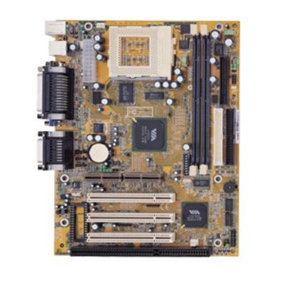
The MICRO ATX VI16 mainboard is a high-performance all-in-one system
®
®
®
mainboard. This mainboard supports Intel
Pentium
processor/Pentium
TM
®
®
processor with MMX
technology, Cyrix
/IBM
6x86/6x86L/6x86MX/MII,
®
and AMD
K6/K6-2/K6-III processors.
The mainboard uses the highly integrated Apollo MVP4. The Apollo MVP4
is a PC Socket-7 system logic North Bridge with integrated 2D/3D Graphics
Accelerator. The core logic portion of the chip is based on the popular
100MHz VIA Apollo MVP3 chipset with enhanced features and graphics
accelerator based on the Cyber9398DVD from Trident Microsystems. The
VT82C686A Super I/O PCI integrated Peripheral Controller (PSIPC) is a high
integration, high performance, power efficient and high compatibility device
that supports Intel and non-Intel based processors plus PCI bus bridge
functionality to make a complete Microsoft PC98-compliant PCI/ISA system.
The VT82C686A supports PCI-to-ISA bus controller, four USB ports, dual
bus-master IDE with Ultra DMA33/66, AC97 Basic Audio, System Hardware
Monitoring, and integrated "Super I/O functionality".
This Mainboard with Apollo MVP4 coupled with VT82C686A is a ideal
performance energy efficient, and highly integrated computer systems.
1-1
Advertisement
Table of Contents

Subscribe to Our Youtube Channel
Related Manuals for MSI MS-5187


Summary of Contents for MSI MS-5187
- Page 1 CHAPTER 1 INTRODUCTION Chapter 1 INTRODUCTION The MICRO ATX VI16 mainboard is a high-performance all-in-one system ® ® ® mainboard. This mainboard supports Intel Pentium processor/Pentium ® ® processor with MMX technology, Cyrix /IBM 6x86/6x86L/6x86MX/MII, ® and AMD K6/K6-2/K6-III processors. The mainboard uses the highly integrated Apollo MVP4.
-
Page 2: Mainboard Features
CHAPTER 1 INTRODUCTION 1.1 Mainboard Features l Socket 7 supports Intel ® ® Pentium processor with MMX technology. l The Cyrix ® ® 6x86/6x86L/6x86MX/MII and AMD K6/K6-2/K6-III proces- sors are also supported. Chipset l VIA ® VT82C501(MVP4) chipset. (North bridge) - support 66/100MHz FSB - integrated AGP 2D/3D Graphics Accelerator - support PC66/PC100 SDRAM memory module... - Page 3 CHAPTER 1 INTRODUCTION On-Board IDE l An IDE controller provides IDE HDD/CD-ROM with PIO, Bus Master and UltraDMA-33/66 operation modes. l Can connect up to four IDE devices. On-Board Peripherals l On-Board Peripherals include: - 1 floppy port supports 2 FDD with 360K, 720K, 1.2M, 1.44M and 2.88Mbytes.
- Page 4 CHAPTER 1 INTRODUCTION Mounting l 6 mounting holes. System Hardware Monitor (optional) l CPU Fan Revolution Detect l CPU Fan Control (the fan will automatically stop when the system enters suspend mode) l System Voltage Detect l CPU Overheat Warning. l Display Actual Current Voltage Other Features l LAN Wake-Up...
-
Page 5: Mainboard Layout
Apollo MVP4 Top: Midi/ Game Port JCD1 Bottom: BATT Line-Out JAUX1 Line-In MODEM1 JBAT1 JSDIN1 JBTCK1 PCI SLOT 1 VT82C686A PCI SLOT 2 JWOL1 JMDM1 PCI SLOT 3 JGL1 SFAN1 JGS1 JFP1 ISA SLOT 1 MS-5187 MICRO ATX VI16 Mainboard... -
Page 6: Cpu Installation Procedures
Chapter 2 Hardware Installation 2.1 Central Processing Unit: CPU ® ® The Micro ATX VI16 mainboard operates with Intel Pentium processor/ ® ® Pentium processor w/MMX technology, Cyrix /IBM 6x86/6x86L/ ® 6x86MX/MII, and AMD K6/K6-2/K6-III processors. It could operate with 2.2V to 3.2V processors. -
Page 7: Cpu Core Speed Derivation Procedure
2.1-2 CPU Core Speed Derivation Procedure 1. The DIP Switch SW1 (1, 2, and 3) are used to set the Core/Bus (Fraction) ratio of the CPU. The actual core speed of the CPU is the Host Clock Frequency multiplied by the Core/Bus ratio. For example: CPU Clock 66MHz... - Page 8 2.1-3 Processor Voltage Setting The jumper Switch JV1 (1-5) is used to set the processor Vcore voltage setting. Vcore OPEN SHORT OPEN OPEN OPEN SHORT SHORT OPEN OPEN OPEN OPEN OPEN SHORT OPEN OPEN OPEN OPEN OPEN SHORT OPEN SHORT OPEN OPEN SHORT...
-
Page 9: Fan Power Connectors: Cfan1/Sfan1
2.1-4 Fan Power Connectors: CFAN1/SFAN1 These connectors support system cooling fan with + 12V. It supports three pin head connector. When connecting the wire to the connector, always take note that the red wire is the positive and should be connected to the +12V, the black wire is Ground and should be connected to GND. - Page 10 2.1-5 CPU Speed and Voltage Setting: SW1, JV1 To adjust the speed and voltage of the CPU, you must know the specifications of your CPU (always ask the vendor for CPU specifi- ® cations). Then refer to Table 2.1 (Intel processors), Table 2.2 ®...
- Page 11 ® Table 2.1 Intel processors ® ® Intel Pentium processors with MMX technology CPU Speed & Voltage Type VI/O Vcore 166MHz 1 2 3 4 5 6 7 8 3.3 2.8 200MHz 1 2 3 4 5 6 7 8 233MHz 1 2 3 4 5 6 7 8 Note: If you encounter a CPU with different voltage, just go to Section 2.1-3 and look...
- Page 12 ® Table 2.2 Cyrix processors ® Cyrix 6x86 processor uses PR to rate the speed of their processors based ® ® on Intel Pentium processor core speed. For example PR150 (120MHz) has ® ® 150MHz core speed of Intel Pentium processor but has 120MHz core ®...
-
Page 13: Cpu Voltage
® Cyrix 6x86MX Processor CPU Speed CPU Voltage Type VI/O Vcore PR200 (66 x 2.5) 1 2 3 4 5 6 7 8 PR233 (75 x 2.5) 1 2 3 4 5 6 7 8 (66 x 3) 1 2 3 4 5 6 7 8 (83 x 2) 1 2 3 4 5 6 7 8 PR266... - Page 14 ® Table 2.3 AMD Processor ® K6/K6-2/K6-3 Processor CPU Voltage CPU Speed Type VI/O Vcore 166MHz 1 2 3 4 5 6 7 8 200MHz 1 2 3 4 5 6 7 8 233MHz 1 2 3 4 5 6 7 8 266MHz 1 2 3 4 5 6 7 8 300MHz...
- Page 15 A battery must be used to retain the mainboard configuration in CMOS RAM. Short 1-2 pins of JBAT1 to store the CMOS data. JBAT1 Keep Data Clear Data Note: You can clear CMOS by shorting 2-3 pin, while the system is off. Then, return to 1-2 pin position.
-
Page 16: Memory Bank Configuration
2.3-1 Memory Bank Configuration The mainboard supports a maximum memory size of 256MB(64-bit technol- ogy) or 512MB(128-bit technology for SDRAM: It provides two 168-pin unbuffered DIMMs (Double In-Line Memory Module) sockets. It supports 8 MB to 128 Mbytes DIMM memory module. 2-11... -
Page 17: Memory Installation Procedures
2.3-2 Memory Installation Procedures A. How to install a DIMM Module Single Sided DIMM Double Sided DIMM 1. The DIMM slot has 2 Notch Keys “VOLT and DRAM”, so the DIMM memory module can only fit in one direction. 2. Insert the DIMM memory module vertically into the DIMM slot. Then push it in. -
Page 18: Memory Population Rules
2.3-3 Memory Population Rules 1. Supports only SDRAM DIMM. 2. To operate properly, at least one 168-pin DIMM module must be in- stalled. 3. This mainboard supports Table Free memory, so memory can be installed on DIMM1 or DIMM 2 in any order. 4. -
Page 19: Case Connector: Jfp1
2.4 Case Connector: JFP1 The Power Switch, Reset Switch, Power LED, Speaker, and HDD LED are all connected to the JFP1 connector block. Reset Switch Power Switch Speaker Power Buzzer (short pin) JFP1 2-14... -
Page 20: Power Switch
2.4-1 Power Switch Connect to a 2-pin push button switch. This switch has the same feature with JRMS1. 2.4-2 Reset Switch Reset switch is used to reboot the system rather than turning the power ON/ OFF. Avoid rebooting while the HDD LED is lit. You can connect the Reset switch from the system case to this pin. -
Page 21: Floppy Disk Connector: Fdd
2.5 Floppy Disk Connector: FDD The mainboard also provides a standard floppy disk connector FDD that supports 360K, 720K, 1.2M, 1.44M and 2.88M floppy disk types. This connector supports the provided floppy drive ribbon cables. 2-16... -
Page 22: Hard Disk Connectors: Ide1 & Ide2
2.6 Hard Disk Connectors: IDE1 & IDE2 The mainboard has a 32-bit Enhanced PCI IDE and Ultra DMA33/66 Con- troller that provides PIO mode 0~4, Bus Master, and Ultra DMA 33/66 function. It has two HDD connectors IDE1 (primary) and IDE2 (secondary). You can connect up to four hard disk drives, CD-ROM, and other devices to IDE1 and IDE2. -
Page 23: Atx 20-Pin Power Connector: Jpwr1
2.7-1 ATX 20-pin Power Connector: JPWR1 This connector supports the power button on-board. Using the ATX power supply, functions such as Modem Ring Wake-Up and Soft Power Off are supported by this mainboard. This power connector supports instant power on function which means that system will boot up instantly when the power connector is inserted on the board. - Page 24 2.7-2 Remote Power On/Off Switch: JRMS1 Connect to a 2-pin push button switch. During OFF state, press once and the system turns on. During ON stage, push once and the system goes to sleep mode: pushing it more than 4 seconds will change its status from ON to OFF.
-
Page 25: Irda Infrared Module Connector: Ir1
2.8 IrDA Infrared Module Connector: IR1 The mainboard provides one infrared (IR1) connector for IR modules. This connector is for optional wireless transmitting and receiving infrared module. You must configure the setting through the BIOS setup to use the IR function. - Page 26 The mainboard has a 9-pin male DIN connector for serial port COM A. This port is a 16550A high speed communication port that send/receive 16 bytes FIFOs. You can attach a mouse or a modem cable directly into this connec- tor.
-
Page 27: Vga Db 15 Pin Connector
2.10 VGA DB 15 Pin Connector The mainboard provides a DB 15-pin connector to connect to a VGA monitor. Analog Video Display Connector(DB15-S) Signal Description Green Blue Not used Ground Ground Ground Ground Not used Ground Not used Horizontal Sync Vertical Sync 2-22... - Page 28 The mainboard provides a 25 pin female centronic connector for LPT. A parallel port is a standard printer port that also supports Enhanced Parallel Port(EPP) and Extended capabilities Parallel Port(ECP). See connector and pin definition below: Parallel Port (25-pin Female) LPT 1 PIN DEFINITION SIGNAL...
-
Page 29: Keyboard Connector: Jkbms1
® The mainboard provides a standard PS/2 mouse mini DIN connector for ® ® attaching a PS/2 mouse. You can plug a PS/2 mouse directly into this connector. The connector location and pin definition are shown below: Pin5 Mouse Clock Pin6 Pin3 Pin4... -
Page 30: Joystick/Midi Connectors
2.14 Joystick/Midi Connectors You can connect joystick or game pad to this connector. Joystick/MIDI 2.15 Audio Port Connectors Line Out is a connector for Speakers or Headphones. Line In is used for external CD player, Tape layer, or other audio devices. Mic is a connector for the microphones. -
Page 31: Usb Connectors
2.16 USB Connectors The mainboard provides a UHCI(Universal Host Controller Interface) Universal Serial Bus root for attaching USB devices like: keyboard, mouse and other USB devices. You can plug the USB device directly to this connector. USB Port 2 1 2 3 4 USB Port 1 SIGNAL -Data0... - Page 32 Attach a power saving switch to JGS1. When the switch is pressed, the system immediately goes into suspend mode. Press any key and the system wakes up. JGS1 2-27...
- Page 33 JGL1 can be connected with an LED. There are two types of LED that you can use: 3-pin LED or 2-pin LED(ACPI request). When the 2-pin LED is connected to JGL1, the light will turn green, when system is On. During sleep mode, the 2-pin LED will change color from Green to Orange.
- Page 34 The JWOL1 connector is for use with LAN add-on cards that supports Wake Up on LAN function. To use this function, you need to set the “Wake-Up on LAN” to enable at the BIOS Power Management Setup. JWOL1 SIGNAL 5VSB MP_WAKEUP Note: LAN wake-up signal is active “high”.
- Page 35 The JMDM1 connector is for use with Modem add-on card that supports the Modem Wake Up function. JMDM1 SIGNAL MDM_WAKEUP 5VSB Note: Modem wake-up signal is active “low”. Note: To be able to use this function, you need a power supply that provide enough power for this feature.
- Page 36 2.21 Modem-In: MODEM1 The connector is for Modem with internal voice connector. SPK IN GND MIC OUT MODEM1 SPK_IN is connected to the Modem Speaker Out connector. MIC_OUT is connected to the Modem Microphone In connector. 2-31...
- Page 37 This connector is used for DVD Add on Card with Line In connector. LGND R JAUX1 2-32...
- Page 38 This connector is for CD-ROM audio connector. LGND R JCD1 2-33...
- Page 39 The Audio/Modem Riser specification is an open industry-standard specification that defines a hardware scalable Original Equipmet Manufacturer (OEM) mainboard riser board and interface, which supports both audio and modem. JSDIN JBTCK1 Feature JBTCK1 JSDIN1 Onboard AC97 Audio and Modem Riser Card AMR Card 2-34...
- Page 40 The TV-Out Interface is a MSI in-house design which support TV-out or PanelLink function. To be able to utilize both AMR and PTI simultaneously, you need to use MSI product like MS-5967 & MS-5966. 2-35...
- Page 41 JPL1 can be connected with an LED. When the system is powered on., the LED will lit. When the system is shutdown, the LED will ceased to lit. JPL1 2-36...
-
Page 42: Award Bios Setup
® Chapter 3 AWARD BIOS SETUP ® Award BIOS ROM has a built-in Setup program that allows users to modify the basic system configuration. This type of information is stored in battery-backed RAM (CMOS RAM), so that it retains the Setup information when the power is turned off. -
Page 43: Status Page Setup Menu/Option Page Setup Menu
® Power on the computer and press <Del> immediately to allow you to enter Setup. The other way to enter Setup is to power on the computer. When the below message appears briefly at the bottom of the screen during the POST (Power On Self Test), press <Del>... -
Page 44: Standard Cmos Setup
® ® Once you enter Award BIOS CMOS Setup Utility, the Main Menu (Figure 1) will appear on the screen. The Main Menu allows you to select from twelve setup functions and two exit choices. Use arrow keys to select among the items and press <Enter>... - Page 45 ® Chipset Features Setup This setup page includes all the items of chipset special features. Power Management Setup This category determines the power consumption for system after setting the specified items. Default value is Disable. PCI Configuration Setup This category specifies the IRQ level for PCI and ISA devices. Load BIOS Defaults BIOS Defaults will indicate the value required by the system for safe performance.
- Page 46 ® The items in Standard CMOS Setup Menu are divided into 10 catego- ries. Each category includes no, one or more than one setup items. Use the arrow keys to highlight the item and then use the <PgUp> or <PgDn> keys to select the value you want in each item.
-
Page 47: Primarymaster/Primaryslave Secondarymaster/Secondary Slave
® Date The date format is <day><month> <date> <year>. Day of the week, from Sun to Sat, determined by BIOS. Read-only. month The month from Jan. through Dec. date The date from 1 to 31 can be keyed by numeric function keys. - Page 48 ® If the controller of HDD interface is ESDI, the selection shall be “Type 1”. If the controller of HDD interface is SCSI, the selection shall be “None”. If the controller of HDD interface is CD-ROM, the selection shall be “None”.
-
Page 49: Anti-Virus Protection
® ROM PCI/ISA BIOS (2A5LEM4F) BIOS FEATURES SETUP AWARD SOFTWARE, INC. Anti-Virus Protection : Disabled Video BIOS Shadow :Enabled CPU Internal Cache : Enabled C8000-CBFFF Shadow :Disabled External Cache : Enabled CC000-CFFFF Shadow :Disabled D0000-D3FFF Shadow :Disabled Quick Power on Self Test : Enabled D4000-D7FFF Shadow :Disabled Boot From LAN First... -
Page 50: Cpu Internal Cache
® Disabled No warning message to appear when anything attempts to access the boot sector or hard disk (default) partition table. Enabled Activates automatically when the system boots up causing a warning message to appear when anything attempts to access the boot sector of hard disk partition table. - Page 51 ® Boot Sequence This category determines which drive the computer searches first for the disk operating system (i.e., DOS). The settings are A,C,SCSI/C,A,SCSI/ C,CD-ROM,A/CD-ROM,C,A/D,A,SCSI/E,A,SCSI/F,A,SCSI/SCSI,A,C/ SCSI,C,A/C only, LS/ZIP,C. Default value is A, C, SCSI. Swap Floppy Drive Switches the floppy disk drives between being designated as A and B.
-
Page 52: Security Option
® Security Option This category allows you to limit access to the system and Setup, or just to Setup. System The system will not boot and access to Setup will be denied if the correct password is not entered at the prompt. Setup(default) The system will boot, but access to Setup will be denied if the correct password is not entered... -
Page 53: Video Bios Shadow
® OS Selection for DRAM > 64MB ® Allows OS2 to be used with > 64 MB of DRAM. Settings are Non- OS/2 (default) and OS2. Set to OS/2 if using more than 64MB and running ® OS/2 Report No FDD For WIN 95 ®... - Page 54 ® The Chipset Features Setup option is used to change the values of the chipset registers. These registers control most of the system options in the computer. Choose the “CHIPSET FEATURES SETUP” from the Main Menu and the following screen will appear. ROM PCI/ISA BIOS(2A5LEM4F) Bank 0/1 DRAM Timing :SDRAM 10ns...
- Page 55 ® Bank 0/1 DRAM Timing Bank 2/3 DRAM Timing The DRAM timing is controlled by the DRAM Timing Registers. The Timings programmed into this register are dependent on the system design. Slower rates may be required in certain system designs to support loose layouts or slower memory.
- Page 56 ® System BIOS Cacheable Select Enabled allows caching of the system BIOS ROM at F000h- FFFFFh, resulting in better system performance. However, if any program writes to this memory area, a system error may result. Enabled (default) BIOS access cached Disabled BIOS access not cached Memory Hole...
- Page 57 ® Onchip Sound This item allows you to enabled or disabled the onboard sound chip. To enabled the onboard audio, set this item to enabled. Then, short JRTCK1 pin 1-2 and JSDIN pin 1-2. Onchip Modem This item allows you to enabled or disabled the Soft Wave Modem for AMR(Modem Riser Card).
-
Page 58: Power Management
® The Power Management Setup will appear on your screen like this: ROM PCI/ISA BIOS (2A5LEM4F) POWER MANAGEMENT SETUP AWARD SOFTWARE, INC. IRQ3(COM2) :Primary Power Management :User Define IRQ4(COM1) :Primary PM Control by APM :Yes IRQ5(LPT2) :Primary Video Off Method :DPMS Support IRQ6(FDD) :Primary... -
Page 59: Video Off After
® Power Management User Define Users can configure their own power management. Min Saving Pre-defined timer values are used such that all timers are in their MAX value. Max Saving Pre-defined timer values are used such that all timers are in their MIN value. PM Control by APM System BIOS will ignore APM when power managing the system. - Page 60 ® MODEM Use IRQ Name the interrrupt request (IRQ) line assigned to the modem (if any) on your system. Activity of the selected IRQ always awakens the system. The settings are NA, 3, 4, 5, 7, 9, 10, or 11. Reserve IRQ 9 ®...
-
Page 61: Soft-Off By Pwrbtn
® HDD Power Down Disable HDD’s motor will not shut off. Defines the continuous HDD idle time before 1 Min/2 Min/ the HDD enters the power saving mode (motor 3 Min/4 Min/ off). BIOS will turn off the HDD’s motor when 5 Min/6 Min/ time is out. -
Page 62: Rtc Alarm Resume
® PM Events Award BIOS defines 7 PM events in the power management mode (Doze &suspend). The user can initialize any PM Events to be Enable or Disable. When the system detects all of the enabled events do not have any activity, it will start the system Doze timer first if the Power Management is not Disabled. -
Page 63: Pnp Os Installed
® You can manually configure the PCI Device’s IRQ. The following pages tell you the options of each item & describe the meanings of each options. ROM PCI/ISA BIOS (2A5LEM4F) PNP/PCI CONFIGURATION SETUP AWARD SOFTWARE, INC. PnP OS Installed :Yes CPU to PCI Write Buffer :Enabled Resources Controlled By... -
Page 64: Resources Controlled By
® Resources Controlled By By Choosing “Auto” (default), the system BIOS will detect the system resource and automatically assign the relative IRQ and DMA Channel for each peripheral. By Choosing “Manual”, the user will need to assign IRQ & DMA for add-on cards. - Page 65 ® IRQ-15 assigned to : PCI/ISA PnP DMA-0 assigned to : PCI/ISA PnP DMA-1 assigned to : PCI/ISA PnP DMA-3 assigned to : PCI/ISA PnP DMA-5 assigned to : PCI/ISA PnP DMA-6 assigned to : PCI/ISA PnP DMA-7 assigned to : PCI/ISA PnP The above settings will be shown on the screen only if “Manual”...
-
Page 66: Assign Irq For Vga
® PCI#2 Access #1 Retry Enabled PCI#2 will be disconnected, if max retries are attempted without success. Disabled PCI#2 will not be disconnected until access is finish. Assign IRQ for VGA Lets the user choose which IRQ to assign for VGA card. 3-25... - Page 67 ® This Main Menu item loads the default system values. If the CMOS is corrupted the defaults are loaded automatically. Choose this item and the following message appears: “ Load Setup Defaults (Y / N) ? N “ To use the Setup defaults, change the prompt to “Y” and press < Enter > Note: The Setup defaults can be customized to increase performance.
- Page 68 ® This Special Features Setup is used by System Hardware Monitor chipset. You can manually change the value of each option. ROM PCI/ISA BIOS (2A5LEM4F) INTEGRATED PERIPHERALS AWARD SOFTWARE, INC. ********* SYSTEM MONITOR ******** ******** POST SHOWING ******** CPU Fan Detected :Enabled CPU Fan RPM :6367...
- Page 69 ® CPU Fan RPM During Enabled, this will monitor the RPM of your CPU fan. System Temperature/CPU Temperature This will show the System and CPU temperature. CPU Critical Temp This option is for setting the critical temperature level for the proces- sor.
- Page 70 ® ROM PCI/ISA BIOS (2A5LEM4F) INTEGRATED PERIPHERALS AWARD SOFTWARE, INC. Onboard Parallel Mode :ECP/EPP Onchip IDE First Channel :Enabled ECP Mode Use DMA Onchip IDE Second Channel:Enabled EPP Mode Select :EPP1.9 IDE Prefetch Mode :Enabled IDE HDD Block Mode :Enabled Onboard Legacy Audio :Enabled Primary Master PIO...
- Page 71 ® IDE Prefetch Mode Enabled/Disabled IDE HDD Block Mode Enabled/Disabled Enabled allows the Block mode access for the IDE HDD. Primary Master PIO Auto/Mode0/Mode1-4 Primary Slave PIO Auto/Mode0/Mode1-4 Secondary Master PIO Auto/Mode0/Mode1-4 Secondary Slave PIO Auto/Mode0/Mode1-4 For these 4 IDE options, choose “Auto” to have the system BIOS auto detect the IDE HDD operation mode for PIO access.
-
Page 72: Onboard Serial Port
® IOnboard FDD Controller Enabled/Disabled The system has an on-board Super I/O chip with a FDD controller that supports 2 FDDs for 360K/720K/1.2M/1.44M/ 2.8M. Choose “Enabled” to use the on- board FDD controller for accessing the FDD. Otherwise choose “Disabled” to use the off-board FDD controller. -
Page 73: Onboard Parallel Mode
® UART2 Mode This item allows you to determine which Infra Red (IR) function of onboard I/O chip. If you choose IR function, the COM 2 will not function. Onboard Parallel Port Disabled There is a built-in parallel port on the on-board Super I/O chipset that pro- (3BCH/IRQ7)/ vides Standard, ECP, and EPP features. -
Page 74: Onboard Legacy Audio
® “ECP Mode Use DMA” At this time the user can choose between DMA chan- nels 3 or 1. The onboard parallel port is EPP Spec. compliant, so after the user chooses the onboard parallel port with the EPP function, the following message will be displayed on the screen: “EPP Mode Select.”... - Page 75 ® This Main Menu item lets you configure the system so that a pass- word is required each time the system boots or an attempt is made to enter the Setup program. Supervisor Password allows you to change all CMOS settings but the User Password setting doesn’t have this function.
- Page 76 ® You can use this utility to automatically detect the characteristics of most hard drives. When you enter this utility, the screen asks you to select a specific hard disk for Primary Master. If you accept a hard disk detected by the BIOS, you can enter “Y”...
-
Page 77: Graphics Features
CHAPTER 4 VIA CHIPSET DRIVER Chapter 4 VIA CHIPSET DRIVER 1. Overview The MVP4 integrates an AGP 2.0 - compliant 2D/3D AGP graphics controller into the north bridge of the chipset. Packed with features, the controller incorporates a 64-bit 2D/3D graphics engine and video accelerator with advanced DVD video and optional TV output capability. -
Page 78: System Requirements
CHAPTER 4 VIA CHIPSET DRIVER 1.3 System Requirements This section describes system requirements for the VGA Driver installa- tion and Usage. ® Computer Intel Pentium processor ® K6/K6-2/K6-III processor ® Cyrix MX/MII processor Monitor VGA Support, mimimum 640x480 resolu- tion ®... - Page 79 CHAPTER 4 VIA CHIPSET DRIVER 2. Driver Setup & Usage Procedures for Windows ® Insert the CD-title into your CD-ROM drive. The CD will auto-run and will display the four icons in the monitor “VIA Chipset Drivers”, “VIA AC97 PCI Sound Drivers”, “VIA Enhance VGA Drivers” and “Download VIA Drivers”.
- Page 80 CHAPTER 4 VIA CHIPSET DRIVER VIA AC97 PCI Sound Drivers installation procedure: Step 1: Insert the provided CD_ROM disk into the CD-ROM drive. Step 2: Look for the CD_ROM drive, double click on the CD_ROM icon. This will show the setup screen. Step 3: Click on “VIA AC97 PCI Sound Drivers”...
- Page 81 CHAPTER 4 VIA CHIPSET DRIVER Enable the Ultra DMA Driver for IDE Driver Step 1: Insert the provided CD-ROM disk into the CD-ROM drive. Step 2: Look for the CD-ROM drive, double click on the CD-ROM icon. This will show the setup screen. Step 3: Click on the “VIA Chipset Drivers”...
-
Page 82: Windows Nt
CHAPTER 4 VIA CHIPSET DRIVER 3. Windows NT 4.0 ® ® Install Windows NT 4.0 Service Pack 3 or the latest version before installing the VIA drivers. Insert the CD-title in the CD-ROM drive. The CD will auto-run and will display four icons on the screen “VIA Chipset Drivers”, “VIA AC97 PCI Sound Drivers”, “VIA Enhance VGA Drivers”... - Page 83 CHAPTER 4 VIA CHIPSET DRIVER 3.2 VIA AC97 PCI Sound Drivers Installation Procedure: Step 1: Insert the provided CD_ROM disk into the CD-ROM drive. Step 2: Look for the CD_ROM drive, double click on the CD_ROM icon. This will show the setup screen. Step 3: Click on “VIA AC97 PCI Sound Drivers”...
- Page 84 CHAPTER 4 VIA CHIPSET DRIVER 3.4 Enable the Ultra DMA for IDE Driver: Step 1: Insert the provided CD-ROM disk into the CD-ROM drive. Step 2: Look for the CD-ROM drive, double click on the CD-ROM icon. This will show the setup screen. Step 3: Click on the “VIA Chipset Drivers”...
Need help?
Do you have a question about the MS-5187 and is the answer not in the manual?
Questions and answers