Table of Contents
Advertisement
Available languages
Available languages
FCC-B Radio Frequency Interference Statement
This equipment has been tested and found to comply with the limits for a class B digital device, pursuant
to part 15 of the FCC rules. These limits are designed to provide reasonable protection against harmful
interference in a residential installation. This equipment generates, uses and can radiate radio frequency
energy and, if not installed and used in accordance with the instruction manual, may cause harmful
interference to radio communications. However, there is no guarantee that interference will occur in a
particular installation. If this equipment does cause harmful interference to radio or television reception,
which can be determined by turning the equipment off and on, the user is encouraged to try to correct the
interference by one or more of the measures listed below.
4
Reorient or relocate the receiving antenna.
4
Increase the separation between the equipment and receiver.
4
Connect the equipment into an outlet on a circuit different from that to which the receiver is
connected.
4
Consult the dealer or an experienced radio/ television technician for help.
Notice 1
The changes or modifications not expressly approved by the party responsible for compliance could void
the user's authority to operate the equipment.
Notice 2
Shielded interface cables and A.C. power cord, if any, must be used in order to comply with the emission
limits.
VOIR LA NOTICE D'NSTALLATION AVANT DE RACCORDER AU RESEAU.
This device complies with Part 15 of the FCC Rules. Operation is subject to the following two conditions:
(1) this device may not cause harmful interference, and
(2) this device must accept any interference received, including interference that may cause undesired
operation
Micro-Star International
MS-7143
G52-M7143X4
i
Advertisement
Table of Contents

Related Manuals for MSI MS-7143


Summary of Contents for MSI MS-7143
- Page 1 This device complies with Part 15 of the FCC Rules. Operation is subject to the following two conditions: (1) this device may not cause harmful interference, and (2) this device must accept any interference received, including interference that may cause undesired operation Micro-Star International MS-7143 G52-M7143X4...
- Page 2 Copyright Notice The material in this document is the intellectual property of MICRO-STAR INTERNATIONAL. We take every care in the preparation of this document, but no guarantee is given as to the correctness of its contents. Our products are under continual improvement and we reserve the right to make changes without notice.
-
Page 3: Safety Instructions
Safety Instructions 1. Always read the safety instructions carefully. 2. Keep this User Manual for future reference. 3. Keep this equipment away from humidity. 4. Lay this equipment on a reliable flat surface before setting it up. 5. The openings on the enclosure are for air convection hence protects the equipment from overheating. Do not cover the openings. -
Page 4: Weee Statement
MSI will comply with the product take back requirements at the end of life of MSI-branded products that are sold into the EU. You can return these products to local collection points. - Page 5 Srpski Da bi zaštitili prirodnu sredinu, i kao preduzeće koje vodi računa o okolini i prirodnoj sredini, MSI mora da vas podesti da… Po Direktivi Evropske unije ("EU") o odbačenoj ekektronskoj i električnoj opremi, Direktiva 2002/96/EC, koja stupa na snagu od 13. Avgusta 2005, proizvodi koji spadaju pod "elektronsku i električnu opremu" ne mogu više biti odbačeni kao običan otpad i proizvođači ove opreme biće prinuđeni da uzmu natrag ove...
- Page 6 Table of Content English...1 Français ...13 Deutsch...25 简体中文 ...39 繁體中文 ...51 日本語...63...
-
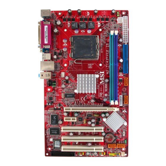
Page 7: Layout
Introduction Thank you for choosing the 915PL/ P Neo (MS-7143 v2.X) Series ATX mainboard. The 915PL/ P Neo Series is based on Intel 915PL/ 915P & Intel ICH6 chipsets for optimal system efficiency. Designed to fit the advanced Intel the 915PL/ P Neo Series delivers a high performance and professional desktop platform solution. -
Page 8: Specifications
Supports up to 2GB memory size without ECC. l Supports dual channel DDR333/ DDR400 MHz. (For the updated supporting memory modules, please visit http://www.msi.com.tw/program/products/mainboard/mbd/pro_mbd_trp_list.php ) Slots l One PCI Express x16 slot (supports PCI Express Bus specification v1.0a compliant). - Page 9 On-Board Peripherals l On-Board Peripherals includes: - 1 floppy port supports 2 FDDs with 360K, 720K, 1.2M, 1.44M and 2.88Mbytes. - 2 serial ports and 1 parallel port supports SPP/EPP/ECP mode. - 8 USB 2.0 ports (Rear * 4/ Front * 4). - 3 audio (Line-In/Line-Out/Mic) ports.
-
Page 10: Lga775 Cpu/Cooler Installation
CPU from overheating. Overclocking This motherboard is designed to support overclocking. However, please make sure your components are able to tolerate such abnormal setting, while doing overclocking. Any attempt to operate beyond product specifications is not recommended. We do not guarantee the damages or risks caused by inadequate operation or beyond product specifications. - Page 11 Note: If you want to uninstall the CPU, align the 4 points (see Point 8 for details) again and push the clip to lift up the CPU. MSI Reminds You... 1. Confirm if your CPU cooler is firmly installed before turning on your system.
-
Page 12: Power Supply
2GB. To operate properly, at least one DIMM module must be installed. (For the updated supporting memory modules, please visit http://www.msi.com.tw/program/products/mainboard/mbd/pro_mbd_trp_list.php) Install at least one DIMM module on the slots. Memory modules can be installed on the slots in any order. -
Page 13: Ide Connectors: Ide1
Slave drive. You must configure second hard drive to Slave mode by setting the jumper accordingly. MSI Reminds You... If you install two hard disks on cable, you must configure the second drive to Slave mode by setting its jumper. Refer to the hard disk documentation supplied by hard disk vendors for jumper setting instructions. -
Page 14: Front Panel Audio/Usb Connectors
Intel Front Panel I/O Connectivity Design Guide. MSI Reminds You... If you do not want to connect to the front audio header, pins 5 & 6, 9 & 10 have to be jumpered in order to have signal output directed to the rear audio ports. -
Page 15: Pci Express Slots
PCI Express Slots The PCI Express slots, as a high-bandwidth, low pin count, serial, interconnect technology, support Intel highest performance desktop platforms utilizing the Intel Pentium 4 processor with HT Technology. PCI Express architecture provides a high performance I/O infrastructure for Desktop Platforms with transfer rates starting at 2.5 Giga transfers per second over a PCI Express x1 lane for Gigabit Ethernet, TV Tuners, 1394 controllers, and general purpose I/O. -
Page 16: Bios Setup
BIOS Setup Power on the computer and the system will start POST (Power On Self Test) process. When the message below appears on the screen, press <DEL> key to enter Setup. Press DEL to enter Setup If the message disappears before you respond and you still wish to enter Setup, restart the system by turning it OFF and On or pressing the RESET button. -
Page 17: Frequency/Voltage Control
Settings: [Enabled], [Disabled]. Spread Spectrum When the motherboard’s clock generator pulses, the extreme values (spikes) of the pulses creates EMI (Electromagnetic Interference). The Spread Spectrum function reduces the EMI generated by modulating the pulses so that the spikes of the pulses are reduced to flatter curves. -
Page 18: Load Bios Default
and performance. But if you are plagued by EMI, select the desired range for EMI reduction. Remember to disable Spread Spectrum function if you are overclocking, because even a slight jitter can introduce a temporary boost in clock speed which may just cause your overclocked processor to lock up. - Page 19 Introduction Félicitations, vous venez d’acquérir une carte mère ATX 915PL/ P Neo (MS-7143 v2.X) Series Les 915PL/ P Neo Series sont basées sur les chipsets Intel Intel 915PL/ 915P & Intel ICH6 offrant un système très performant. La carte fonctionne avec les processeurs Intel 533/ 800MHz (LGA775), la 915PL/ P Neo Series est très performante et offre une solution...
- Page 20 Supporte jusqu’à Pentium 4 3XX, 5XX, 6XX(EM64T) ou supérieur. l Supporte la technologie Intel Hyper-Threading. l Supporte la technologie Intel EIST. (Pour les dernières mises à jours concernant les CPU, vous pouvez visiter : http://www.msi.com.tw/program/products/mainboard/mbd/pro_mbd_cpu_support.php.) Chipset l Chipset Intel 915PL/ 915P - Supporte FSB 533/ 800MHz - Supporte l’interface PCI Express x 16/ x 1...
- Page 21 Périphériques Intégrés l Périphériques Intégrés Inclus : - 1 port floppy supportant 2 FDD avec 360K, 720K, 1.2M, 1.44M et 2.88Mbytes. - 2 ports série, 1 port parallèle supportant les modes SPP/EPP/ECP. - 8 ports USB 2.0 (Arrière * 4, avant * 4). - 3 ports audio (Line-In/Line-Out/Mic).
-
Page 22: Panneau Arrière
PC. (Pour une mise à jour sur les CPU, veuillez visiter http://www.msi.com.tw/program/products/mainboard/mbd/pro_mbd_cpu_support.php) MSI Vous Rappelle... Surchauffe Une surchauffe endommagera sérieusement le CPU et le système. Soyez toujours sur du bon fonctionnement des ventilateurs et radiateurs pour protéger le CPU d’une surchauffe. - Page 23 Prendre le CPU Clip bleu de MSI et le faire tourner afin qu’il s’aligne avec le socket. Il faut ensuite retirer la protection qui se trouve sur le socket de la carte mère. Veuillez ne pas toucher aux broches du socket.
- Page 24 besoins. Volt Le DDR DIMM ne possède qu’une encoche en son centre. Ainsi il n’est possible de monter le module que dans un seul sens. Insérez le module de mémoire DIMM verticalement dans le slot. Puis appuyez dessus Le clip en plastique situé de chaque côté du module va se fermer automatiquement. Alimentation La carte mère supporte les alimentations ATX.
- Page 25 MSI Vous Rappelle... Si vous voulez installer deux disques durs, vous devez configurer le second en Esclave en configurant le cavalier. Se référer à la documentation du disque dur pour les instructions. Connecteurs Serial ATA contrôlés par Intel ICH6: SATA1/2/3/4 Le Southbridge de cette carte est Intel ICH6, qui supporte quatre connecteurs de série SATA1 ~...
-
Page 26: Connecteur Audio Front Panel
Panel I/O Connectivity MSI Vous rappelle... Si vous ne voulez pas connecter l’audio en façade à l’aide des broches 5 & 6, 9 & 10 doivent être recouvertes par un cavalier pour envoyer le signal vers les ports audio à l’arrière. Autrement le connecteur Line-Out à... -
Page 27: Pci Interrupt Request Routing
Slots PCI Express Les slots PCI Express possèdent une large bande passante L’architecture PCI Express procure une infrastructure I/O haute performance avec un taux de transfert de 2.5 GB/S sur un connecteur PCI Express 1x (Gigabit Ethernet, Tuner TV, contrôleur 1394...) Elle délivre des performances importantes pour les applications vidéos (multimedia, 3D…) De plus, l’architecture PCI Express procure une bande passante deux fois plus importante que celle procurée avec l’AGP 8x avec un taux de transfert de 4.0 GB/s pour le PCI Express 16 x... -
Page 28: Setup Du Bios
Setup du BIOS Lorsque le PC démarre le processus de POST (Power On Self Test) se met en route. Quand le message ci-dessous apparaît, appuyer sur <DEL> pour accéder au Setup. DEL: Setup Si le message disparaît avant que n’ayez appuyé sur la touche, redémarrez le PC à l’aide du bouton RESET. - Page 29 Load BIOS Defaults Utiliser ce menu pour charger les paramètres par défaut du BIOS. Set Password Utiliser ce menu pour entrer un mot de passe Save & Exit Setup Sauvegarder les changements du CMOS et sortir de l’utilitaire de Setup. Exit Without Saving Abandonner tous les changements et sortir de l’utilitaire de Setup.
- Page 30 Memory Voltage En ajustant le voltage DDR, vous pouvez augmenter la vitesse DDR. Tout changement effectué sur cette option peut entraîner une instabilité, donc changer le voltage DDR à long terme n’est pas recommandé. PCI Express Voltage Ce champs vous permet d’ajuster le voltage du PCI Express voltage pour une meilleure performance de votre PCI Express lorsque vous overclockez.
- Page 31 Einleitung Danke, dass Sie das 915PL/ P Neo Series (MS-7143 v2.X) ATX Mainboard gewählt haben. Das 915PL/ P Neo Series basiert auf den Intel 915PL/ 915P und Intel ICH6 Chipsätzen und ermöglicht so ein optimales und effizientes System. Entworfen, um die fortschrittlichen Intel Prescott 533/ 800MHz Prozessoren im LGA775 Package aufzunehmen, stellt das 915PL/ P Neo Series die ideale Lösung zum Aufbau eines professionellen Hochleistungsdesktopsystems dar.
-
Page 32: Spezifikationen
Unterstützt den Speicherausbau auf bis zu 2GB ohne ECC. l Unterstützt Dual Channel DDR 333/400 MHz. (Um den letzten Stand bezüglich der unterstützten Speichermodule zu erhalten, besuchen Sie bitte http://www.msi.com.tw/program/products/mainboard/mbd/pro_mbd_trp_list.php ) Schnittstellen l Ein PCI Express x16 Slot (unterstützt PCI Express Bus, gemäß der Spezifikation V1.0a). - Page 33 Peripherieanschlüsse onboard l hierzu gehören: - 1 Anschluss für zwei Diskettenlaufwerke mit 360 KB, 720 KB, 1,2 MB, 1,44 MB oder 2,88 MB - 2 Serielle Schnittstelle und 1 Parallele Schnittstelle, die die Betriebsmodi SPP/EPP/ECP unterstützt - 8 USB 2.0 Anschlüsse (4 hintere/ 4 vordere) - 3 Audioanschlüsse (Eingang/ Ausgang/ Mikrofon).
-
Page 34: Hinteres Anschlusspaneel
Überhitzung beschädigt die CPU und das System nachhaltig, stellen Sie stets eine korrekte Funktionsweise des CPU Kühlers sicher, um die CPU vor Überhitzung zu schützen. Übertakten Dieses Motherboard wurde so entworfen, dass es Übertakten unterstützt. Stellen Sie jedoch bitte sicher, dass die betroffenen Komponenten mit den abweichenden Einstellungen während des Übertaktens zurecht kommen. - Page 35 Folgen Sie den Schritten unten, um die CPU und den Kühler ordnungsgemäß zu installieren. Ein fehlerhafter Einbau führt zu Schäden an der CPU und dem Mainboard. Die CPU verfügt über eine Abdeckung auf der Anschlussfläche an der Unterseite, um die Kontakte der CPU vor Schaden zu bewahren.
- Page 36 MSI weist darauf hin... 1. Stellen Sie den festen Sitz Ihres CPU- Kühlers fest, bevor Sie das System anschalten. 2. Überprüfen Sie die Temperatur der CPU im “Health Status” der Hardwareüberwachung im BIOS. 3. Um Schäden zu vermeiden, berühren Sie keinesfalls die Pins des CPU Sockels.
- Page 37 Laufwerk verwalten. Das zweite Laufwerk muss durch das entsprechende Setzen einer Steckbrücke als Slave eingestellt werden. MSI weist darauf hin... Verbinden Sie zwei Laufwerke über ein Kabel, müssen Sie das zweite Laufwerk im Slave-Modus konfigurieren, indem Sie entsprechend den Jumper setzen. Entnehmen Sie bitte die Anweisun- gen zum Setzen des Jumpers der Dokumentation der Festplatte, die der Festplattenhersteller zur Verfügung stellt.
- Page 38 MSI weist darauf hin... Bitte falten Sie das Serial ATA Kabel nicht in einem Winkel von 90 Grad, da dies zu Datenverlusten während der Datenübertragung führt. CD-Eingang: CD1 Hier kann das Audiokabel des CD-ROM Laufwerkes angeschlossen werden. Stromanschlüsse für Lüfter: CPUFAN1/SYSFAN1 Der vierpolige Anschluss CPUFAN1 (Prozessorlüfter) und der...
- Page 39 Peripheriegeräte anzuschließen, Festplattenlaufwerke, Digitalkameras, MP3-Player, Drucker, Modems und ähnliches. MSI weist darauf hin... Bitte beachten Sie, dass Sie die mit VCC (Stromführende Leitung) und GND (Erdleitung) bezeichneten Pins korrekt verbinden müssen, ansonsten kann es zu Schäden kommen. Steckbrücke zur CMOS-Löschung: JBAT1 Auf dem Mainboard gibt es einen sogenannten CMOS Speicher (RAM), der über eine Batterie...
- Page 40 PCI (Peripheral Component Interconnect) Slots Die PCI Steckplätze ermöglichen Ihnen den Einsatz von PCI- Karten, um das System Ihren Anforderungen anzupassen. Stellen Sie vor dem Einsetzen oder Entnehmen von Karten sicher, dass Sie den Netzstecker gezogen haben. Studieren Sie bitte die Anleitung zur Erweiterungskarte, um jede notwendige Hard - oder Softwareeinstellung für...
-
Page 41: Bios Setup
BIOS Setup Nach dem Einschalten beginnt der Computer den POST (Power On Self Test - Selbstüberprüfung nach Anschalten). Sobald die Meldung unten erscheint, drücken Sie die Taste <Entf>(<Del>), um das Setup aufzurufen. DEL: Setup Wenn die Nachricht verschwindet, bevor Sie reagieren und Sie möchten immer noch ins Setup, starten Sie das System neu, indem Sie es erst AUS- und danach wieder ANSCHALTEN, oder die “RESET”-Taste am Gehäuse betätigen. -
Page 42: Frequency/Voltage Control
H/W Monitor Dieser Eintrag gibt den „Gesundheitszustand“ Ihres PCs wieder. Frequency/Voltage Control Hier können Sie Einstellungen zu Taktfrequenz und Spannung vornehmen. Load BIOS Defaults In diesem Menü können Sie jene Werkseinstellungen für das BIOS laden, die der Hersteller für den leistungsoptimierten Systembetrieb vorgibt. Set Password Verwenden Sie dieses Menü, um das Kennwort einzugeben. - Page 43 Spread Spectrum Pulsiert der Taktgenerator des Motherboards, erzeugen die Extremwerte (Spitzen) der Pulse Elektromagnetische Interferenzen (sog. EMI). Die “Spread Spectrum” Funktion reduziert die erzeugten EMI, indem die Pulse so moduliert werden, das die Pulsspitzen zu flacheren Kurven reduziert werden. Sollten Sie keine Probleme mit Interferenzen haben, belassen Sie es bei der Einstellung [Disabled] (ausgeschaltet), um bestmögliche Systemstabilität und -leistung zu gewährleisten.
-
Page 44: Load Bios Default
Load BIOS Default Hier können Sie die Voreinstellungen für den stabilen Betrieb laden, die der Mainboardhersteller vorgibt. - Page 45 简介 感谢您购买 915PL/ P Neo(MS-7143 v2.X)Series ATX 主板。915PL/ P Neo Series 是基于 Intel 915PL/ 915P & Intel ICH6 芯片组,支持 LGA775 封装的 Intel 915PL/ P Neo Series 提供了高性能、专业化的桌面平台解决方案。 布局 T: mouse B: keyboard Line-In Line-Out B:Mic Codec Chip Winbond W83627THF B IOS...
- Page 46 支持 2 条无缓冲 DDR SDRAM 的 DIMM l 支持的最大容量为 2GB,无 ECC l 支持双通道 DDR333/ DDR400 MHz (要了解内存模组的最新信息,请访问 http://www.msi.com.tw/program/products/mainboard/mbd/pro_mbd_trp_list.php ) 插槽 l 1 条 PCI Express x16 插槽(兼容 PCI Express Bus 规格 v1.0a) l 1 条 PCI Express x1 插槽(兼容 PCI Express Bus 规格 v1.0a)...
- Page 47 板载周边 l 板载周边包括: - 1 个软驱接口,支持 2 台 360K, 720K, 1.2M, 1.44M 和 2.88 Mbytes 的软驱 - 2 个串行接口和 1 个支持 SPP/EPP/ECP 模式的并行接口 - 8 个 USB 2.0 端口(后置* 4/ 前置* 4) - 3 个音频(Line-In/Line-Out/Mic)端口 - 1 个 RJ-45 LAN 插孔 音频...
-
Page 48: 中央处理器:Cpu
硬件安装 这一章主要告诉您如何安装 CPU,内存,扩展卡,也会告诉您怎样设置主板上的跳线,并提供连 接外围设备的指导,如鼠标,键盘等。安装时,请谨慎拿各零部件并且按照安装说明的步骤进行。 中央处理器:CPU 本主板支持 LGA775 封装的 Intel 插槽,可使 CPU 安装过程简化。当您在安装 CPU 时,请务必确认您使用的 CPU 带有防过热的散 热片和降温风扇。 如果您的 CPU 没有散热片和降温风扇, 请与经销商联系,购买或索取以上设备, 并在开机之前妥善安装。 要了解关于 CPU 的最新信息,请访问 http://www.msi.com.tw/program/products/mainboard/mbd/pro_mbd_cpu_支持.php. 微星提醒您 ... 温度过高 温度过高会严重损害 CPU 和系统,请务必确认所使用的降温风扇始终能够正常工作,保护 CPU 以免过热烧毁。 超频 此主板的设计支持超频。但是,请先确认您的组件在超频过程中可支持非正常设定。我们并不推荐 您在标准规格以外的情况下运行此设备。 对于任何非正常的设定或在标准规格以外运行本设备所造 成的损失,我们不予担保。 LGA775 CPU 和风扇的安装(CPU 夹子为选配)... - Page 49 4. 只要 CPU 尚未安装,请把塑料盖覆在 CPU 插槽上,以免插槽的针脚受损。 5. 请注意 CPU 的安插 / 拔取的寿命为 20 次。因此我们建议您不要频繁地插拔 CPU 。 内存 主板提供 2 条插槽,可以插入 184-pin 无缓冲的 DDR333 / DDR400 DDR SDRAM 内存,支持的 内存最大容量为 2GB。您至少要安装一条内存在插槽,以保证系统正常工作。 (要了解内存模组支 持的更新,请访问 http://www.msi.com.tw/program/products/mainboard/mbd/pro_mbd_trp_list.php ) 至少要安装一条内存模组在插槽。内存条可以按任何次序被安装。您也可以根据自己的需要,来安 装单面或双面的内存模组。 安装 DDR 内存 Volt Notch...
- Page 50 DDR DIMM 内存条的中央仅有一个缺口。 将 DDR 内存垂直插入 DDR 插槽中,并确保缺口的正确位置。 DIMM 插槽两边的塑料卡口会自动闭合。 电源适配器 主板使用 ATX 结构的电源适配器给主板供电。在连接电源适配器之前,请务必确认所有的组件都 已正确安装,并且不会造成损坏。建议您使用功率为 300W 或以上的电源。 ATX 24-Pin 电源接口:ATX1 此接口可连接 ATX 24-Pin 电源适配器。在与 ATX 24-Pin 电源适配器 相连时,请务必确认,电源适配器的接头安装方向正确,针脚对应顺 序也准确无误。将电源接头插入,并使其与主板电源接口稳固连接。 若您喜欢,也可以使用 20-pin 的 ATX 电源适配器。若您要使用 20-pin 的 ATX 电源适配器,请顺着 pin 1 和 pin 13 插上电源适配器(参阅右 示图例)...
- Page 51 由 ICH6 控制的 Serial ATA 接口:SATA1/2/3/4 此主板的南桥芯片是 Intel ICH6,它支持 4 个 serial 接口 SATA1~4。 它们都是高速串行 Serial ATA 端口。每个接口都支持第一代 Serial ATA,数据速 率达到 150 MB/s。SATA1~4 接口都兼容 Serial ATA1.0 规格。 微星提醒您 ... 请勿把 serial ATA 数据线折成 90 度,否则会造成传输时数据的丢失。 CD-In 接口:CD1 此接口为 CD-ROM 的音频接口。 风扇电源接口:CPUFAN1/SYSFAN1 此...
-
Page 52: Pci Express
前置 USB 接口:JUSB1/ JUSB2 主板提供 2 个 USB2.0 的接口 JUSB1、JUSB2。USB 2.0 技术提高数据传输速度,达到 480Mbps,是 USB1.1 的 40 倍。它可连接高速数据传输速率的 USB 界面周边设备,如 USB HDD、数码相机、MP3 播放器、打印机、调制解调器 等。 微星提醒您 ... 请注意, VCC 和 GND 的针脚必须安插正确,否则会引起主板的损毁。 清除 CMOS 跳线:JBAT1 主板上建有一个 CMOS RAM,其中保存的系统配置数据需要通过一枚外置电池来维持。CMOS RAM 是在每次启动计算机的时候引导操作系统的。若您想清 除保存在 CMOS RAM 中的系统配置信息,可使用 JBAT1 (清 除... - Page 53 PCI(周边设备连接)插槽 PCI 插槽可安装您所需要的扩展卡。当您在安装或拆 卸扩展卡的时候,请务必确认已将电源插头拔除。同 时,请仔细阅读扩展卡的说明文件,安装和设置此扩展卡必须的硬件和软件,比如跳线或 BIOS 设 置。 PCI 中断请求队列 IRQ 是中断请求队列和中断请求确认的缩写,将设备的中断信号送到微处理器的硬件列表。PCI 的 IRQ 针脚一般都是连接到如下表所示的 PCI 总线的 INT A# ~ INTD# 引脚: Order1 PCI Slot 1 INT C# PCI Slot 2 INT D# PCI Slot 3 INT A# Order2 Order3 Order4 INT D# INT A#...
- Page 54 BIOS 设置 计算机加电后,系统将会开始 POST (加电自检)过程。当屏幕上出现以下信息时,按<DEL>键 即可进入设定程序。 DEL: Setup 如果信息在您做出反应前就消失了,而您仍需要进入 Setup,请关机后再开机或按机箱上的 Reset 键, 重启您的系统。您也可以同时按下<Ctrl>、<Alt>和<Delete>键来重启系统。 主页面 Standard CMOS Features(标准 CMOS 特性设定) 使用此菜单可对基本的系统配置进行设定。如时间,日期等。 Advanced BIOS Features(高级 BIOS 特性设定) ® 使用此菜单可对 Award 系统的高级特性进行设定。 Advanced Chipset Features(高级芯片组特性设定) 使用此菜单可以修改芯片组寄存器的值,优化系统的性能表现。 Integrated Peripherals(整合周边设定) 使用此菜单可以对周边设备进行特别的设定。 Power Management Setup(电源管理特性设定) 使用此菜单可以对系统电源管理进行特别的设定。 PNP/PCI Configurations(PnP/PCI 配置)...
- Page 55 Set Password(设置密码) 使用此项菜单可设置密码。 Save & Exit Setup(保存后退出) 保存对 CMOS 的修改,然后退出 Setup 程序。 Exit Without Saving(不保存退出) 放弃对 CMOS 的修改,然后退出 Setup 程序。 频率/电压控制 Adjust CPU Ratio(调整 CPU 倍频) 此项用于调整 CPU 倍频的。设置范围从[8]到[50]。 Auto Detect PCI Clk(自动侦测 PCI 时钟) 此项用于自动侦测 PCI 插槽。当设置为[Enabled],系统将移除(关闭)闲置的 PCI 插槽时钟,以 最小化电池干扰(EMI)...
- Page 56 Memory Voltage(内存电压) 调整 DDR 电压可以提高 DDR 速度。但这样的调整会影响系统的稳定性,所以建议您不要改变默 认设置作为长期使用。 PCI Express Voltage(PCI Express 电压) PCI Express 电压在此项可调整,可让您在超频时提高 PCI Express 设备性能。但此项可能会影响 到系统的稳定性。 载入 BIOS 缺省值 您可载入主板制造商提供的稳定系统的 BIOS 设置缺省值。...
- Page 57 簡介 感謝您選購 915PL/ P Neo (MS-7143 v2.X) ATX 系列主機板,The 915PL/ P Neo 系列主機板係採 用 Intel 915PL/ 915P 及 Intel ICH6 晶片組,以期提供系統最佳化效能。並針對新一代的 Intel Prescott 533/ 800MHz(LGA775 插槽)處理器來設計的,故 915PL/ P Neo 系列可提供您高效能及 專業的桌上型電腦平台解決方案。 主機板配置圖 T: mouse B: keyboard Line-In Line-Out B:Mic Codec...
- Page 58 支援兩條 unbuffered 的 DDR SDRAM 記憶體(DIMM 模組)。 l 支援高達 2GB 的記憶體容量(non-ECC)。 l 支援雙通道 DDR333/ DDR400 MHz 的記憶體。 (有關最新的記憶體模組訊息,請您至微星科技網站 http://www.msi.com.tw/program/products/mainboard/mbd/pro_mbd_trp_list.php ) 插槽 l 一個 PCI Express x16 插槽(支援 PCI Express 遵循匯流排 1.0a 版規格)。 l 一個 PCI Express x1 插槽(支援 PCI Express 遵循匯流排 1.0a 版規格)。...
- Page 59 內建週邊輸出 l 內建週邊包括: - 一個軟碟機埠,可支援兩部 360K/720K/1.2M/1.44M/2. 88MB 規格的軟碟機。 - 二個序列埠及一個平行埠,可支援 SPP/EPP/ECP 模式。 - 八個 USB2.0 版連接埠(背板*4/面板*4)。 - 三個音效輸入/音效輸出/麥克風輸入埠。 - 一個 RJ-45 網路連接埠。 音效 l AC97 連接控制器整合在 Intel ICH6 晶片之中。 l 6 通道音效晶片(ADI AD1888)。 - 符合 AC97 v2.3 規格。 - 符合 PC2001 規格對聲音效能的要求。 區域網路...
-
Page 60: 中央處理器(Cpu
硬體安裝 本章將教您安裝中央處理器、記憶體模組、擴充卡及設定主機板上的跨接器,附帶並告訴您如何連 接滑鼠鍵盤等週邊裝置,進行安裝時請小心處理零組件並遵守安裝步驟。 中央處理器(CPU) 本主機板支援 Intel Pentium 4 Prescott 處理器,所使用的 CPU 插槽稱之為 LGA775。當您在安裝 CPU 時,請確認附有散熱器與冷卻風扇以防止 CPU 過熱。如果沒找到散熱器與冷卻風扇,請洽詢 經銷商購買,並在啟動電腦之前,將散熱器正確地安裝在您的主機板上。 有關最新的 CPU 訊息,請您至微星科技網站: http://www.msi.com.tw/program/products/mainboard/mbd/pro_mbd_cpu_support.php. MSI 提醒您... 溫度過高 溫度過高將會嚴重損壞您的 CPU 及系統,請確保您的散熱風扇可以正常運作,以保護 CPU ,避免 發生過熱的情形。 超頻使用 本主機板儘管設計成為可超頻運作。然而當您將其調整為超頻運作時,請確認您的系統元件及週邊 是可以忍受如此非正常的設定。任何在非本產品規格建議下的運作方式,我們將不保證其造成的損 壞及運轉時的風險。 安裝 LGA775 規格的中央處理器及風扇(CPU 扣環是選擇性備配) 當您在安裝 CPU 時,請確認附有散熱器與冷卻風扇以防止 CPU 過熱。如果沒找到散熱器與冷卻... - Page 61 12. 輕輕的壓下裝載拉桿,且確定拉桿有卡入固定鈎之中。 13. 將散熱器與主機板的洞對齊,壓下散熱器直到其 4 個扣環與主機板的洞 密合。 14. 壓下四邊鈎子固定住散熱器,然後轉動卡榫(依照上面標記的正確方 向)。定住鈎子。 15. 翻轉一下主機板以確認環扣已正確的安插完畢。 請注意:若您要移除處理器,請遵照 4 要點(詳見上述第 8 點)壓下環扣將處理器取上來。 MSI 提醒您... 1. 在您打開電源之前,請確認您的散熱器已穩固的安裝在處理器上。 2. 在 BIOS 畫面之中找到有關硬體監控的選項 ( 檢查處理器的温度 ) 。 3. 不要去碰觸處理器插座的針腳,以避免造成損壞。 4. 當您沒有安裝處理器時,一定要將塑膠蓋放回插座以保護處理器插座的針腳。 5. 請記得插座能讓您插換處理器約 20 次,在此建議您更換次數勿太頻繁。 . 記憶體 本主機板提供兩條 184-接腳非緩衝式的 DDR333 / DDR400 DDR SDRAM 模組插槽,最高可支援...
- Page 62 本主機板具有一個 32 位元增強型 PCI IDE 及 Ultra DMA 66/100 控制器,可提供 PIO 模 式 0~4、主控匯流排以及 Ultra DMA 66/100 等功能。你可透過 IDE 連接線連接二部硬 碟、CD-ROM、120MB 軟碟機及其他的 IDE 裝置。 第一部硬碟必須連接到 IDE1,IDE1 可以連接一部主要裝置及一部隸屬裝置。您必須根 據跳線設定將第二部裝置設定為隸屬裝置。 MSI 提醒您... 假如您在同一條連接線上安裝了兩組硬碟,您必須設定硬碟的跨接器( Jumper ) ,將第二組硬碟指 定到隸屬模式。關於硬碟的設定方式,請參考硬碟廠商所提供之說明。 PWR OK +12V +5 V...
- Page 63 Intel ICH6 的串列式 ATA 連接器(SATA):SATA1/2/3/4 本主機的南橋晶片(Intel ICH6)支援四個串列式 ATA 連接器,SATA1~4 是雙通道 高速介面埠,均支援第一代的 SATA 介面規格,每秒逹 150 MB 的傳輸速度。所 有的 SATA 均完全符合 Serial ATA 1.0 版的規格,每一個 SATA 連接器均可連接一個硬碟設備。 MSI 提醒您... 請勿將 SATA 的排線轉折超過 90 度以上,否則會導致資料傳輸上的錯誤。 CD-In 輸入連接器:CD1 此連接器是供光碟機的音訊連接器使用。 冷卻風扇連接器:CPUFAN1/SYSFAN1 在 4 針腳的 CPUFAN1 (處理器冷卻風扇)及 3 針腳 SYSFAN1 (系統冷卻風扇)這兩個連接器以+12V 的電壓供應電力給系統的...
-
Page 64: Pci Express 插槽
主機板提供二個面板 USB2.0 標準的連接器接頭 JUSB1 & JUSB2。USB2.0 技術可大幅提昇資料傳輸速率,最高可達 480Mbps,為 USB1.1 的 40 倍,適用於高速 USB 介面的週 邊裝置,例如:USB 硬碟、數位相機、MP3 播放器、印表 機、數據機及相關週邊裝置。 MSI 提醒您... 請您注意, VCC 及 GND 的針腳位置必須正確的連接,否則可能造成損壞。 清除 CMOS 跨接器:JBAT1 主機板上有一個 CMOS RAM,它是利用主機板上的水銀電池 來保存 BIOS 的設定。CMOS RAM 可以讓系統在每次開機的 時候,依照使用者設定的 BIOS 來開機。如果你想要將 BIOS 回復到原廠的設定值,可以使用... - Page 65 PCI 的中斷請求表 IRQ 是中斷請求(Interrupt Request)的英文縮寫,它是一個可讓裝置傳送中斷訊號至微處理器的硬 體線路。PCI 的 IRQ 腳位通常都連接到 PCI 匯流排的 INT A#~INT D#腳位,如下所示: Order1 PCI Slot 1 INT C# PCI Slot 2 INT D# PCI Slot 3 INT A# BIOS 設定 打開電腦的電源後,系統就會開始 POST(開機自我測試)程序。當下列訊息出現在螢幕上時,按下 <DEL>鍵進入設定程式。 如果此訊息在您反應之前就已消失 , 而您還想要進入設定時 , 將系統關閉重新啟動或是按下 RESET 按鈕。您也可以同時按下<Ctrl>、<Alt>及<Delete>鍵重新啟動系統。...
- Page 66 Integrated Peripherals(整合型週邊) 使用此選單指定整合型週邊裝置的設定。 Power Management Setup(電源管理設定) 使用此選單指定電源管理的設定。 PNP/PCI Configurations(PNP / PCI 組態) 如果系統支援 PnP / PCI,本選項便會出現。 H/W Monitor(硬體狀況) 此選單可顯示您電腦目前的硬體及健康的狀態。 Frequency/Voltage Control(頻率/電壓控制) 使用此選單指定您的頻率/電壓控制設定。 Load BIOS Defaults(載入出廠預設值) 使用此功能清單載入 BIOS 的出廠預設值,以獲得最穩定的系統作業。 Set Password(BIOS 設定密碼) 使用此選單設定 BIOS 密碼。 Save & Exit Setup(儲存並離開設定) 將變更儲存到 CMOS 並離開設定程式。 Exit Without Saving(離開但不儲存)...
- Page 67 頻率/電壓控制 Adjust CPU Ratio(調整 CPU 倍頻比率) 這個項目可讓你調整 CPU 的運作時脈是幾倍於主機板的外頻,設定範圍:[8]到[50]。 Auto Detect PCI Clk(自動偵測 PCI 時脈) 這個項目可讓你自動偵測 PCI 插槽。當設定為開啟時,為了要減少電磁干擾(EMI)的發生,系統 將會除去(關閉)時脈產生器傳送空的 PCI 插槽,可設定值:[Enabled 啟用]、[Disabled 關閉]。 Spread Spectrum(頻譜擴散) 當主機板的時脈產生脈衝時,會同時產生額外的 EMI (電磁波干擾),頻譜擴散功能乃在於減少電磁 波的干擾。因此若您沒有電磁波干擾的問題,則將其設為[Disabled 關閉],以期系統的穩定及最佳 效能。若您要防止電磁波干擾,則開啟此選項以降低電磁的干擾。請記得,若想要執行超頻的動作 時,您可將之設定為[Disabled 關閉],因為即使調整一點點時脈也可能導致超頻的 CPU 鎖住。 CPU Clock(CPU 主時脈) 此選項可讓您為 CPU 此選項可讓您為匯流排(以 MHz 計)選擇適當的時脈頻率,而當您欲超頻運作 時則可將...
- Page 68 載入 BIOS 預設值 您可以使用此功能載入 BIOS 的出廠(主機板廠商)預設值,以獲得最佳化的系統作業。...
- Page 69 マザーボードのレイアウト 915PL/ P Neo (MS-7143 v2.X) シリーズ ATX マザーボードをお買い上げいただき、まことにあ りがとうございます。915PL/ P Neo シリーズは Intel に基づいています。LGA775 ピンパッケージの Intel ザインに準拠している 915PL/ P Neo シリーズはハイ・パフォーマンスおよびプロフェッショナ ル・デスクトップ・ソリューションを提供します。 レイアウト T: mouse B: keyboard Line-In Line-Out B:Mic Codec Chip Winbond W83627THF B IOS FDD1 ® CPUFAN1...
- Page 70 2 本の DDR SDRAM DIMM によるサポート l 最大 2 GB ECC なしのメモリサイズをサポート l DDR333/ DDR400 MHz メモリモジュールをサポート (最新のメモリモジュール対応表は下記のホームページからご参考ください。 http://www.msi.com.tw/program/products/mainboard/mbd/pro_mbd_trp_list.php ) スロット l 1 PCI Express x16 スロット (PCI Express バス規格 v1.0a を準拠). l 1 PCI Express x1 slot (PCI Express バス規格 v1.0a を準拠).
- Page 71 オンボード周辺装置 l オンボード周辺装置は以下のものを含みます。: - 1 フロッピーポートが 360K, 720K, 1.2M, 1.44M, 2.88 バイトの FDD を 2 台サポート - 2 シリアルポート 1 パラレルポート SPP/EPP/ECP モードサポート - 8 USB 2.0 ポート(バックパネル * 4/フロントパネル * 4) - 3 オーディオ(Line-In/Line-Out/Mic)ポート - 1 RJ-45 LAN ジャック Audio l ICH6 チップセットに統合した...
- Page 72 本製品は Intel Pentium 4 プロセッサで動作します。本製品は LGA775 というソケットを使用し ているため CPU のインストールが大変簡単です。 CPU の過剰な発熱を防ぐためには必ずヒート シンクと冷却ファンが必要です。 もしヒートシンクと冷却ファンが見つからない場合は、 販売店 に連絡するか、別途購入してからコンピュータの電源をオンにしてください。 (最新の CPU 対応表は下記のホームページからご参考ください。 http://www.msi.com.tw/program/products/mainboard/mbd/pro_mbd_cpu_support.php. MSI Reminds You... CPU の過熱 CPU が過剰な熱を持つと破損する場合があります。使用される冷却ファンが正常に動作するこ とを必ず確認してから CPU の取り付けを行ってください。 CPU の交換 CPU を交換する間は必ず ATX 電源を切るか、 ATX 電源用ケーブルを接地コンセントから抜いて、 まず CPU の安全を確保してください。...
- Page 73 金属カバーをゆっくりと押し下げます。 CPU 固定レバーをゆっくりと押し下げ、ロックします。 CPU クーラーの四隅のピンをマザーボードの固定穴にあわせ、 ゆっ くりと押し込みます。 位置が正しいことが確認できたら、ホックが固定されるまで押し込 みます。 注意: マザーボード裏面に出た割ピンが開き、正しくロックできたことを 確認してください。 MSI Reminds You... 使用する CPU クーラーは、CPU の熱量に適した物であることを必ず確認してください。 BIOS の H/W Monitor メニュー中の PC Health Status にある CPU 温度情報を確認してく ださい。 CPU ソケットのピンには、決して触れないでください。ソケット破損は保証対象外にな ります。 CPU の信号ピン側には、決して触れないで下さい。変形や腐食の原因となる他、静電気 で破損する場合もあります。 CPU の取り付け取り外しは、20 回以下に留めて下さい。不必要な取り付け取り外しは、...
- Page 74 ATX 24-ピン電源コネクタ: ATX1 このコネクタを使用すると、ATX24-ピン電源に接続することができ ます。ATX 電源へ接続するには、 電源のプラグが正しい方向に挿入さ れ、ピンが適切に配置されていることを確認します。そして電源をコ ネクタの奥まで差し込みます。 20 ピン電源コネクタを採用している従来の ATX+12V 規格に準拠した 電源ユニットやサーバー用 24 ピンコネクタを採用している SSI EPS 電源ユニットも接続することができますが、MSI では推奨しません。 やむを得ず ATX+12V ver. 2.0 規格では無い電源ユニットを接続する場 合は、 適切な変換コネクタを利用して補助電源コネクタに電力を供給 して下さい。 ATX 12V 電源コネクタ: JPW1 この 12V 電源コネクタは、CPU への電源供給で使用されます。 フロッピーディスクコネクタ: FDD1 本製品は 360K、720K、1.2M、1.44M 及び 2.88M のフロッピーディ...
- Page 75 2 つのハードディスク、CD-ROM、120MB フロッピー(将来の BIOS で予約されてい ます) 、その他のデバイスを接続することができます。 1 台目の HDD は必ず IDE1(プライマリ)に接続します。IDE1 にはマスターとスレイブ のデバイスを接続することができますが、 2 台目の HDD を追加する場合は HDD の設 定をジャンパでスレイブに切り替える必要があります。 MSI Reminds You... ハードディスクを 2 台使用する場合は、ジャンパを使用して 2 台目のハードディスクをスレ ーブに設定する必要があります。 ジャンパの設定手順等につきましてはハードディスク製造業者 から用意されましたマニュアルを参照ください。 Serial ATA Connectors controlled by Intel ICH6: SATA1/2/3/4 本製品はサウスブリッジ...
- Page 76 されています。JFP1 は Intel Design Guide に準拠しています。 フロント・パネル・オーディオ・コネクタ: JAUD1 JAUD1 フロント・パネル・オーディオ・コネクタを使 用すると、フロント・パネル・オーディオを接続する ことができます。このコネクタは、Intel I/O Connectivity Design Guide に準拠しています。 MSI Reminds You... フロント・パネル・オーディオ・ヘッダに接続しない場合、信号の出力が背面オーディオ・ポー トへ送信されるようにするため、ピン 5、6、9、10 はジャンパでキャップする必要があります。 フロント USB コネクタ: JUSB1/JUSB2 本製品には 2 つの USB 2.0 ピン・ヘッダーUSB1&USB2 が搭 載されています。USB 2.0 テクノロジーでは、最大スループ ット 480Mbps までデータ伝送率を高速化するため、USB 1.1 の...
- Page 77 PCI Express スロット PCI Express は、周辺機器と通信環境の高速化に対応するべく制定された次世代のシリアルバス 規格です。PCI Express は用途によって 1 レーン(PCI Express 1x )から 16 レーン(PCI Express 16x) まで束ねて使用することが可能で、1 レーンで従来の 32 ビット PCI バスの約 2 倍の、250MB 毎 秒という高速転送を実現しています。ギガビットイーサネットコントローラー、TV チューナー カード、 IEEE1394 カードといった高速なデータ転送を要求されるカードを PCI Express 接続にす ることで、従来以上に高速かつ安定したシステムが構築できます。また、ビデオカードについて は現在主流となっている AGP8x バス(帯域幅 2.1GB 毎秒)から PCI Express 16x(帯域幅 4.0GB 毎秒)への移行が進みます。システムバス全体が...
- Page 78 BIOS Setup コンピュータを起動するとシステムは POST(Power On Self Test)過程に入ります。下記のメッ セージが画面に表示されている間に<DEL>キーを押すと設定画面に入ることができます。 DEL: Setup <DEL>を押す前にこのメッセージが消えてしまった場合、電源をいったん切ってからふたたび 投入するか、 <RESET>を押すかして、 システムを再起動してください。 <Ctrl>、<Alt>、 <Delete> を同時に押しても再起動できます。 メインメニュー Standard CMOS Features システムの基本的な設定をします。例えば﹑時間、日付など。 Advanced BIOS Features システムの特別機能の設定を行います。 Advanced Chipset Features チップセットに関する設定をしてシステムの性能を最適化します。 Integrated Peripherals IDE、シリアル、パラレルなどの各 I/O ポートの設定をします。 Power Management Setup 電源管理に関する設定を行います。 PNP/PCI Configurations プラグアンドプレイや...
- Page 79 Set Password パスワードを設定します。 Save & Exit Setup 変更した CMOS 設定値を保存してセットアップを終了します。 Exit Without Saving 変更した CMOS 設定値を保存せずにセットアップを終了します。 Frequency/Voltage Control Adjust CPU Ratio CPU コア電圧(Vcore)を調整します。選択肢は [8]から[50] まで設定できます。 Auto Detect PCI Clk ここではインストールされた PCI カードのクロック周波数を自動的に認識する機能を有効/無効 に設定することができます。選択肢は Enabled(有効)と Disabled(無効)です。 Spread Spectrum クロックジェネレータがパルスを発生すると、 そのパルスの極値(スパイク) によって EMI(電磁 妨害) が生成されます。Spread Spectrum 機能はパルスを変調することで生成された...
- Page 80 Memory Voltage DDR 速度を上げるために DDR 電圧を調整します。DDR 電圧を変更すると、システムが不安定 になることがあります。そのためデフォルト設定値を変更して長期間使用することは避けてく ださい。 PCI Express Voltage PCI Express の電圧を調整します。PCI Express の電圧を変更すると、システムが不安定になる ことがあります。そのためデフォルト設定値を変更して長期間使用することは避けてください。 Load BIOS Default Load BIOS Default を実行することにより、マザーボードの各種設定を工場出荷時の状態に戻すこ とができます。...
Need help?
Do you have a question about the MS-7143 and is the answer not in the manual?
Questions and answers