Table of Contents
Advertisement
Quick Links
CHAPTER 1
CHAPTER 1
CHAPTER 1
CHAPTER 1
CHAPTER 1
Chapter 1
Introduction
The ATX TX3 mainbard is a high-performance personal computer
mainboard. This mainboard supports Intel
®
Pentium
processor with MMX
processor, and AMD
32-bit PCI (Peripheral Component Interconnect) Local Bus standard slots.
A cache subsystem is configured for 512K cache memory to improve overall
throughput.
The mainboard uses the highly integrated Intel
the PCI/ISA and Green standards, and to provide the Host/PCI bridge. The
®
Intel
82430TX chipset integrates all system control functions such as ACPI
(Advanced Configuration and Power Interface). The ACPI provides more
Energy Saving Features for the OSPM(OS Direct Power Management)
function. The Intel
supporting Ultra DMA/33 IDE that transfer data at the rate of 33MB/s.
The mainboard has an on-board Audio which uses Creative
chipset. The Creative
®
Creative
Wavesynth and Sound Blaster 16 Utility that allows you to play
high quality music for Windows multimedia applications and computer
games.
The mainboard also supports the LM78 System Hardware Monitor
Controller as optional function. The LM78 function includes: CPU chassis/
power fan control, CPU temperature detect and protect, and chassis
intrusion detect.
TM
technology, Cyrix
®
K5/K6 processor. The mainboard also supports four
®
82430TX chipset also improves the IDE transfer rate by
®
Vibra 16X chipset provides Windows applications like
®
®
Pentium
®
6x86/6x86L/6x86MX
®
83430TX chipset to support
1-1
INTRODUCTION
INTRODUCTION
INTRODUCTION
INTRODUCTION
INTRODUCTION
processor and
®
Vibra 16X
Advertisement
Table of Contents

Related Manuals for MSI MS-5153


Summary of Contents for MSI MS-5153
- Page 1 CHAPTER 1 CHAPTER 1 CHAPTER 1 INTRODUCTION INTRODUCTION INTRODUCTION CHAPTER 1 CHAPTER 1 INTRODUCTION INTRODUCTION Chapter 1 Introduction The ATX TX3 mainbard is a high-performance personal computer ® ® mainboard. This mainboard supports Intel Pentium processor and ® ® Pentium processor with MMX technology, Cyrix 6x86/6x86L/6x86MX...
-
Page 2: Mainboard Features
CHAPTER 1 CHAPTER 1 CHAPTER 1 INTRODUCTION INTRODUCTION INTRODUCTION CHAPTER 1 CHAPTER 1 INTRODUCTION INTRODUCTION 1.1 Mainboard Features ® ® ® Socket 7 supports Intel Pentium processor -- Pentium processor w/ technology. ® ® The Cyrix 6x86/6x86L/6x86MX and AMD K5/K6 processors are also supported. - Page 3 CHAPTER 1 CHAPTER 1 INTRODUCTION INTRODUCTION CHAPTER 1 CHAPTER 1 CHAPTER 1 INTRODUCTION INTRODUCTION INTRODUCTION On-Board Peripherals On-Board Peripherals include: - 1 floppy port supports 2FDD with 360K, 720K, 1.2M, 1.44M and 2.88Mbytes. - 2 serial ports (COMA + COMB) - 1 parallel port supports SPP/EPP/ECP mode - 1 IrDA connector or Fast IrDA(reserved) - 1 Consumer IR(reserved)
- Page 4 CHAPTER 1 CHAPTER 1 CHAPTER 1 INTRODUCTION INTRODUCTION INTRODUCTION CHAPTER 1 CHAPTER 1 INTRODUCTION INTRODUCTION BIOS The system board BIOS provides “Plug & Play” BIOS which detects the peripheral devices and expansion cards of the board automatically. The system board provides a Desktop Management Interface(DMI) function which records your system board specifications.
- Page 5 CHAPTER 1 CHAPTER 1 INTRODUCTION INTRODUCTION CHAPTER 1 CHAPTER 1 CHAPTER 1 INTRODUCTION INTRODUCTION INTRODUCTION 1.2 Parts of the Mainboard...
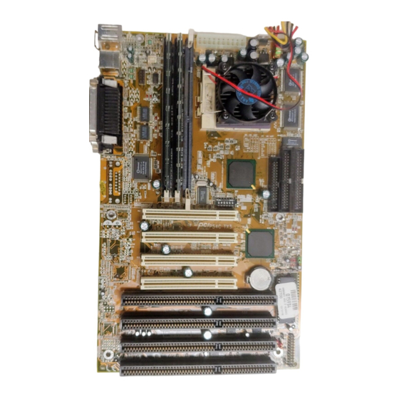
- Page 6 CHAPTER 1 CHAPTER 1 INTRODUCTION INTRODUCTION CHAPTER 1 CHAPTER 1 CHAPTER 1 INTRODUCTION INTRODUCTION INTRODUCTION PS/2 Ports Top: Mouse Bottom: Keyboard USB Ports Top: Port 1 Bottom: Port 2 COM Ports Top: Parallel Bottom: Serial Sound Ports Top: Joystick/Midi Bottom: Line-Out/Line-In/Mic Four 32-Bit PCI SLOTs ®...
-
Page 7: Mainboard Layout
Top: MIDI/ Joystick JRMS3 Bottom: Line Out Line In CD-Line In PCI SLOT 1 FW82371AB PCI SLOT 2 JBAT1 PCI SLOT 3 Creative Vibra 16X BATT PCI SLOT 4 ISA SLOT ISA SLOT JRMS1 LM78 ISA SLOT (optional) ISA SLOT MS-5153... -
Page 8: Cpu Installation Procedures
CHAPTER 2 HARDWARE INSTALLATION Chapter 2 Hardware Installation 2.1 Central Processing Unit: CPU ® ® The ATX TX3 mainboard operates with Intel Pentium processor- ® ® Pentium processor with MMX technology, Cyrix 6x86/6x86L/6x86MX ® and AMD K5/K6 processors. It could operates with 2.0V to 3.52V proces- sors. - Page 9 CHAPTER 2 HARDWARE INSTALLATION 2.1-2 CPU Core Speed Derivation Procedures 1. The mainboard supports different clock frequencies adjusted by SW1 pin 4, 5, and 6. See the following chart to set the different Host Clock Frequencies. Clock 55MHz 60MHz 66MHz 75MHz 68.5MHz Special CPU Clock...
- Page 10 CHAPTER 2 HARDWARE INSTALLATION 2. The DIP Switch SW1 (1, 2, and 3) is used to set the Core/Bus (Fraction) ratio of the CPU. The actual core speed of the CPU is the Host Clock Frequency multiplied by the Core/Bus ratio. For example: CPU Clock 66MHz Core/Bus ratio...
- Page 11 CHAPTER 2 HARDWARE INSTALLATION 2.1-4 CPU Speed Setting: SW1 To adjust the speed of the CPU, you must know the specification of your CPU (always ask the vendor for CPU specificaton). Then, refer to Table 2.1 ® ® ® (Intel Pentium processor/Pentium processor with MMX...
- Page 12 CHAPTER 2 HARDWARE INSTALLATION ® Table 2.1 Intel Processor ® ® Intel Pentium Processor CPU Speed Type 90 MHz 100 MHz 120 MHz 133 MHz 150 MHz 166 MHz 200 MHz ® ® Intel Pentium Processor with MMX Technology 166 MHz 200 MHz 233 MHz...
-
Page 13: Cpu Speed
CHAPTER 2 HARDWARE INSTALLATION ® Table 2.2 Cyrix Processor ® Cyrix processor uses PR to rate the speed of their processors based on ® ® Intel Pentium processor core speed. For example, PR150 (120MHz) has ® ® 150MHz core speed of Intel Pentium processor but has 120MHz core ®... - Page 14 CHAPTER 2 HARDWARE INSTALLATION ® Cyrix 6x86MX Processor CPU Speed Type PR166 (60x2.5) (66x2) PR200 (66x2.5) (75x2) PR233 (66x3) (75x2.5) PR266 (66x3.5) (75x3)
- Page 15 CHAPTER 2 HARDWARE INSTALLATION ® Table 2.3 AMD Processor ® processor uses PR to rate the speed of their processors based on ® ® Intel Pentium processor core speed. For example, PR133 (100MHz) has ® ® 133MHz core speed of Intel Pentium processor but has 100MHz core ®...
- Page 16 CHAPTER 2 HARDWARE INSTALLATION 2.1-5 CPU Fan Power Connectors: JFAN1 / JFAN2 These connectors supports system cooling fan with +12V. It supports three pin head connector. When connecting the wire to the connector, always take note that the red wire is the positive and should be connected to the +12V, the black wire is Ground and should be connected to GND.
-
Page 17: Voltage Setting
CHAPTER 2 HARDWARE INSTALLATION 2.2 Flash ROM Programming Voltage: JP2 This jumper is for setting the Voltage of the Flash ROM BIOS. Voltage Setting +12V (default) Note: a. If you use Winbond or SST Flash ROM, short 1-2 . b. If you use Intel or MXIC Flash ROM , short 1-2 pin. If you want to flash the ROM data, short 2-3, then put it back to 1-2. - Page 18 CHAPTER 2 HARDWARE INSTALLATION 2.3 Flash ROM Boot Block Programming: JP4 This jumper is for setting the boot block area of the Flash ROM BIOS to allow programming. Disable Enable 2-11...
- Page 19 CHAPTER 2 HARDWARE INSTALLATION 2.4 External Battery Connector: JBAT A battery must be used to retain the system board configuration in CMOS RAM. If you use the on-board battery you must short pins of JBAT to keep the CMOS data. JBAT Clear Data Keep Data...
- Page 20 CHAPTER 2 HARDWARE INSTALLATION 2.5 Power Saving LED Connector: JGL Attach a power LED to JGL. This LED will lit to show that the system is in suspend mode. 2-13...
-
Page 21: Pin Definition
CHAPTER 2 HARDWARE INSTALLATION ® 2.6 Creative EMU8000 Wave Table Connector: J11 To connect your EMU8000 Wave Table card to the Vibra 16X chip on the mainboard, you must insert EMU800 card in the ISA slot and connect the cable to J11. PIN DEFINITION Pin # Signal... -
Page 22: Memory Installation
CHAPTER 2 HARDWARE INSTALLATION 2.7 Memory Installation 2.7-1 Memory Bank Configuration The mainboard provides three 168-pin DIMM(Double In-Line Memory) sockets to support a maximum of 256MB of memory. You can use DIMM from 8MB, 16MB, 32MB, to 64MB. A Bank consist of one DIMM socket. It also consists of 2 RAS, with each RAS supporting up to 128MB of memory. -
Page 23: Memory Installation Procedures
CHAPTER 2 HARDWARE INSTALLATION 2.7-2 Memory Installation Procedures A. How to install a DIMM Module Single Sided DIMM Double Sided DIMM 1. The DIMM slot has a two Notch Key “VOLT and DRAM”, so the DIMM memory module can only fit in one direction. 2. -
Page 24: Memory Population Rules
CHAPTER 2 HARDWARE INSTALLATION 2.7-3 Memory Population Rules 1. You can use any kind of DIMM except for BEDO(Burst EDO). 2. You can only used an unbuffered DIMM. 3. To operate properly at least one 168-pin DIMM module must be installed. 4. - Page 25 CHAPTER 2 HARDWARE INSTALLATION 2.8 Case Connector: JFP The Turbo LED, Hardware Reset, Key Lock, Power LED, Power Saving LED, Sleep Switch, Speaker and HDD LED are all connected to the JFP connector block. Speaker Power LED Keylock S l e e p P o w e r S a v i n g S w i t c h...
- Page 26 CHAPTER 2 HARDWARE INSTALLATION 2.8-1 Turbo LED The Turbo LED is always ON. You can connect the Turbo LED from the system case to this pin. (See Figure 2.1) 2.8-2 Hardware Reset Reset switch is used to reboot the system rather than turning the power ON/ OFF.
- Page 27 CHAPTER 2 HARDWARE INSTALLATION 2.9 Floppy Disk Connector: FDC The mainboard also provides a standard floppy disk connector FDD that supports 360K, 720K, 1.2M, 1.44M and 2.88M floppy disk types. You can attach a floppy disk cable directly to this connector. 2-20...
-
Page 28: Hard Disk Connector: Ide1 & Ide2
CHAPTER 2 HARDWARE INSTALLATION 2.10 Hard Disk Connector: IDE1 & IDE2 The mainboard has a 32-bit Enhanced PCI IDE Controller that provide PIO mode 4 and Ultra DMA/33 function. It has two HDD connectors IDE1 (primary) and IDE2 (secondary). You can connect up to four hard disk drives, CD-ROM, 120MB Floppy (reserved for future BIOS) and other devices to IDE1 and IDE2. -
Page 29: Power Supply
CHAPTER 2 HARDWARE INSTALLATION 2.11 Power Supply 2.11-1 ATX 20-pin Power Connector: JWR12 This connector supports the power button on-board. Using the ATX power supply, functions such as Modem Ring Wake-Up and Soft Power Off are supported by this mainboard. Power Connector ATX Power Connector Pin Description -12V... - Page 30 CHAPTER 2 HARDWARE INSTALLATION 2.11-2 Power On/Off Switch: JRMS1/JRMS2 Connect to a 2-pin push button switch. Every time the switch is shorted by pushing it once, the power supply will change its status from OFF to ON. During ON stage, push once and the system goes to sleep mode: pushing it more than 4 seconds will change its status from ON to OFF.
-
Page 31: Irda Infrared Module Connector: Jir1
CHAPTER 2 HARDWARE INSTALLATION 2.12 IrDA Infrared Module Connector: JIR1 The mainboard provides two 5-pin infrared (IR) connectors for IR modules. These connectors are for optional wireless transmitting and receiving infrared module. You must configure the setting through the BIOS setup to use the IR function. - Page 32 CHAPTER 2 HARDWARE INSTALLATION 2.13 CD Line-In: J15/J16/J17 The mainboard provides three different kinds of CD Line-in connectors to let you connect three different kinds of cable provided by the CD-ROM. J16 J15 2-25...
- Page 33 CHAPTER 2 HARDWARE INSTALLATION 2.14 Serial Port Connectors: COM A & COM B The mainboard has two serial ports COMA and COMB. These two ports are 16550A high speed communication ports that send/receive 16 bytes FIFOs. You can attach a mouse or a modem directly into these connectors. 1 2 3 4 5 6 7 8 9 COM A...
-
Page 34: Parallel Port Connector: Lpt
CHAPTER 2 HARDWARE INSTALLATION 2.15 Parallel Port Connector: LPT The mainboard provides a connector for LPT. The parallel port is a standard printer port that also supports Enhanced Parallel Port(EPP) and Extended capabilities Parallel Port(ECP). Parallel Port (25-pin Female) PIN DEFINITION PIN # DEFINITION PIN #... -
Page 35: Usb Connectors: Usb
CHAPTER 2 HARDWARE INSTALLATION ® 2.16 PS/2 Keyboard Connector: PSKBC ® PS/2 Mouse Connector: PSMSC ® The mainboard provides a standard PS/2 keyboard mini DIN connector for attaching a keyboard. You can plug a keyboard cable directly to this connector. ®... -
Page 36: Joystick/Midi Connectors
CHAPTER 2 HARDWARE INSTALLATION 2.18 Joystick/Midi Connectors You can connect joystick or game pads to this connector. Joystick/Midi(15-Pin Female) 2.19 Audio Port Connectors Line Out are connectors for Speakers or Headphones. Line In are used for outside CD player, Tape layer, or other audio devices. And Mic are connec- tor for the microphones. -
Page 37: Award Bios Setup
® CHAPTER 3 CHAPTER 3 AWARD AWARD BIOS SETUP BIOS SETUP CHAPTER 3 CHAPTER 3 CHAPTER 3 AWARD AWARD AWARD BIOS SETUP BIOS SETUP BIOS SETUP Chapter 3 AWARD BIOS SETUP ® ® ® ® ® ® Award BIOS ROM has a built-in Setup program that allows users to modify the basic system configuration. -
Page 38: Status Page Setup Menu/Option Page Setup Menu
® CHAPTER 3 CHAPTER 3 CHAPTER 3 CHAPTER 3 CHAPTER 3 AWARD AWARD AWARD AWARD AWARD BIOS SETUP BIOS SETUP BIOS SETUP BIOS SETUP BIOS SETUP 3.1 Entering Setup 3.1 Entering Setup 3.1 Entering Setup 3.1 Entering Setup 3.1 Entering Setup Power on the computer and press <Del>... -
Page 39: The Main Menu
® CHAPTER 3 CHAPTER 3 CHAPTER 3 CHAPTER 3 CHAPTER 3 AWARD AWARD AWARD AWARD AWARD BIOS SETUP BIOS SETUP BIOS SETUP BIOS SETUP BIOS SETUP 3.3 The Main Menu 3.3 The Main Menu 3.3 The Main Menu 3.3 The Main Menu 3.3 The Main Menu ®... - Page 40 ® CHAPTER 3 CHAPTER 3 AWARD AWARD BIOS SETUP BIOS SETUP CHAPTER 3 CHAPTER 3 CHAPTER 3 AWARD AWARD AWARD BIOS SETUP BIOS SETUP BIOS SETUP Chipset Features Setup This setup page includes all the items of chipset special features. Power Management Setup This category determines the power consumption for system after setting the specified items.
- Page 41 ® CHAPTER 3 CHAPTER 3 AWARD AWARD BIOS SETUP BIOS SETUP CHAPTER 3 CHAPTER 3 CHAPTER 3 AWARD AWARD AWARD BIOS SETUP BIOS SETUP BIOS SETUP 3.4 Standard CMOS Setup 3.4 Standard CMOS Setup 3.4 Standard CMOS Setup 3.4 Standard CMOS Setup 3.4 Standard CMOS Setup The items in Standard CMOS Setup Menu are divided into 10 categories.
-
Page 42: Primarymaster/Primaryslave Secondarymaster/Secondary Slave
® CHAPTER 3 CHAPTER 3 AWARD AWARD BIOS SETUP BIOS SETUP CHAPTER 3 CHAPTER 3 CHAPTER 3 AWARD AWARD AWARD BIOS SETUP BIOS SETUP BIOS SETUP Date The date format is <day><month> <date> <year>. Day of the week, from Sun to Sat, determined by BIOS. - Page 43 ® CHAPTER 3 CHAPTER 3 AWARD AWARD BIOS SETUP BIOS SETUP CHAPTER 3 CHAPTER 3 CHAPTER 3 AWARD AWARD AWARD BIOS SETUP BIOS SETUP BIOS SETUP If the controller of HDD interface is ESDI, the selection shall be “Type 1”. If the controller of HDD interface is SCSI, the selection shall be “None”.
-
Page 44: Virus Warning
® CHAPTER 3 CHAPTER 3 AWARD AWARD BIOS SETUP BIOS SETUP CHAPTER 3 CHAPTER 3 CHAPTER 3 AWARD AWARD AWARD BIOS SETUP BIOS SETUP BIOS SETUP 3.5 BIOS Features Setup 3.5 BIOS Features Setup 3.5 BIOS Features Setup 3.5 BIOS Features Setup 3.5 BIOS Features Setup ROM PCI/ISA BIOS (2A59IM4A) BIOS FEATURES SETUP... -
Page 45: Cpu Internal Cache
® CHAPTER 3 CHAPTER 3 AWARD AWARD BIOS SETUP BIOS SETUP CHAPTER 3 CHAPTER 3 CHAPTER 3 AWARD AWARD AWARD BIOS SETUP BIOS SETUP BIOS SETUP Disabled No warning message to appear when anything (default) attempts to access the boot sector or hard disk partition table. -
Page 46: Boot Sequence
® CHAPTER 3 CHAPTER 3 AWARD AWARD BIOS SETUP BIOS SETUP CHAPTER 3 CHAPTER 3 CHAPTER 3 AWARD AWARD AWARD BIOS SETUP BIOS SETUP BIOS SETUP Boot Sequence This category determines which drive the computer searches first for the disk operating system (ex. DOS). The settings are A,C,SCSI/ LS/ZIP,C/C,A,SCSI/C,CD-ROM,A/CD-ROM,C,A/D,A,SCSI/E,A,SCSI/ F,A,SCSI/SCSI,A,C/SCSI,C,A/C only. - Page 47 ® CHAPTER 3 CHAPTER 3 AWARD AWARD BIOS SETUP BIOS SETUP CHAPTER 3 CHAPTER 3 CHAPTER 3 AWARD AWARD AWARD BIOS SETUP BIOS SETUP BIOS SETUP PCI VGA Palette Snooping Choose Disabled or Enabled. Some graphic controllers which are not VGA compatible, take the output from a VGA controller and map it to their display as a way to provide the boot information and the VGA compatibility.
-
Page 48: Video Bios Shadow
® CHAPTER 3 CHAPTER 3 AWARD AWARD BIOS SETUP BIOS SETUP CHAPTER 3 CHAPTER 3 CHAPTER 3 AWARD AWARD AWARD BIOS SETUP BIOS SETUP BIOS SETUP Video BIOS Shadow Determines whether video BIOS will be copied to RAM for faster execution. -
Page 49: Chipset Features Setup
® CHAPTER 3 CHAPTER 3 AWARD AWARD BIOS SETUP BIOS SETUP CHAPTER 3 CHAPTER 3 CHAPTER 3 AWARD AWARD AWARD BIOS SETUP BIOS SETUP BIOS SETUP 3.6 Chipset Features Setup Chipset Features Setup Chipset Features Setup Chipset Features Setup Chipset Features Setup The Chipset Features Setup option is used to change the values of the chipset registers. -
Page 50: Auto Configuration
® CHAPTER 3 CHAPTER 3 AWARD AWARD BIOS SETUP BIOS SETUP CHAPTER 3 CHAPTER 3 CHAPTER 3 AWARD AWARD AWARD BIOS SETUP BIOS SETUP BIOS SETUP Auto Configuration Choosing Enabled (default) will automatically configure chipset features using default settings. Choose Disable to customize setup. DRAM Timing Sets the DRAM speed at 70ns (default) or 60ns. - Page 51 ® CHAPTER 3 CHAPTER 3 AWARD AWARD BIOS SETUP BIOS SETUP CHAPTER 3 CHAPTER 3 CHAPTER 3 AWARD AWARD AWARD BIOS SETUP BIOS SETUP BIOS SETUP Fast EDO Lead Off Under Auto config., the BIOS will identify which type of DRAM is being used.
- Page 52 ® CHAPTER 3 CHAPTER 3 AWARD AWARD BIOS SETUP BIOS SETUP CHAPTER 3 CHAPTER 3 CHAPTER 3 AWARD AWARD AWARD BIOS SETUP BIOS SETUP BIOS SETUP SDRAM Speculative Read The settings are enable or disable. If you only use One Bank for SDRAM and there’s no EDO or FP mixed together, the setting is Enable.
-
Page 53: Power Management Setup
® CHAPTER 3 CHAPTER 3 AWARD AWARD BIOS SETUP BIOS SETUP CHAPTER 3 CHAPTER 3 CHAPTER 3 AWARD AWARD AWARD BIOS SETUP BIOS SETUP BIOS SETUP 3.7 Power Management Setup 3.7 Power Management Setup 3.7 Power Management Setup 3.7 Power Management Setup 3.7 Power Management Setup The Power Management Setup will appear on your screen like this: ROM PCI/ISA BIOS (2A59IM4A) - Page 54 ® CHAPTER 3 CHAPTER 3 AWARD AWARD BIOS SETUP BIOS SETUP CHAPTER 3 CHAPTER 3 CHAPTER 3 AWARD AWARD AWARD BIOS SETUP BIOS SETUP BIOS SETUP Power Management Disable Global Power Management will be disabled. User Define Users can configure their own power management.
-
Page 55: Video Off After
® CHAPTER 3 CHAPTER 3 AWARD AWARD BIOS SETUP BIOS SETUP CHAPTER 3 CHAPTER 3 CHAPTER 3 AWARD AWARD AWARD BIOS SETUP BIOS SETUP BIOS SETUP Video Off After The settings are N/A, Standby, Doze, or Suspend. This option is for choosing the setting in which the monitor will turn off. -
Page 56: Throttle Duty Cycle
® CHAPTER 3 CHAPTER 3 AWARD AWARD BIOS SETUP BIOS SETUP CHAPTER 3 CHAPTER 3 CHAPTER 3 AWARD AWARD AWARD BIOS SETUP BIOS SETUP BIOS SETUP Suspend Mode Disable System will never enter SUSPEND mode. Defines the continuous idle time before the 1 Min/2 Min/ system enters SUSPEND mode. -
Page 57: Soft-Off By Pwr-Bttn
® CHAPTER 3 CHAPTER 3 AWARD AWARD BIOS SETUP BIOS SETUP CHAPTER 3 CHAPTER 3 CHAPTER 3 AWARD AWARD AWARD BIOS SETUP BIOS SETUP BIOS SETUP Soft-Off by PWR-BTTN The settings are Delay 4 sec or Instant-off. During Delay 4 sec, if you push the switch once, the system goes into suspend mode and if you push it more than 4 seconds, the system will be turned off. - Page 58 ® CHAPTER 3 CHAPTER 3 AWARD AWARD BIOS SETUP BIOS SETUP CHAPTER 3 CHAPTER 3 CHAPTER 3 AWARD AWARD AWARD BIOS SETUP BIOS SETUP BIOS SETUP IRQ 8 Clock Event IRQ[3-7,9-15], NMI : Enabled Primary IDE 0 : Enabled Primary IDE 1 : Disabled Secondary IDE 0 : Disabled...
-
Page 59: Pnp/Pci Configuration Setup
® CHAPTER 3 CHAPTER 3 AWARD AWARD BIOS SETUP BIOS SETUP CHAPTER 3 CHAPTER 3 CHAPTER 3 AWARD AWARD AWARD BIOS SETUP BIOS SETUP BIOS SETUP 3.8 PNP/PCI Configuration Setup 3.8 PNP/PCI Configuration Setup 3.8 PNP/PCI Configuration Setup 3.8 PNP/PCI Configuration Setup 3.8 PNP/PCI Configuration Setup You can manually configure the PCI Device’s IRQ. -
Page 60: Resources Controlled By
® CHAPTER 3 CHAPTER 3 AWARD AWARD BIOS SETUP BIOS SETUP CHAPTER 3 CHAPTER 3 CHAPTER 3 AWARD AWARD AWARD BIOS SETUP BIOS SETUP BIOS SETUP Resources Controlled By By Choosing “Auto”, the system BIOS will detect the system resources and automatically assign the relative IRQ and DMA Channel for each peripheral. - Page 61 ® CHAPTER 3 CHAPTER 3 AWARD AWARD BIOS SETUP BIOS SETUP CHAPTER 3 CHAPTER 3 CHAPTER 3 AWARD AWARD AWARD BIOS SETUP BIOS SETUP BIOS SETUP IRQ-15 assigned to : PCI/ISA PnP DMA-0 assigned to : PCI/ISA PnP DMA-1 assigned to : PCI/ISA PnP DMA-3 assigned to : PCI/ISA PnP...
-
Page 62: Assign Irq For Vga
® CHAPTER 3 CHAPTER 3 AWARD AWARD BIOS SETUP BIOS SETUP CHAPTER 3 CHAPTER 3 CHAPTER 3 AWARD AWARD AWARD BIOS SETUP BIOS SETUP BIOS SETUP Assign IRQ for VGA Lets the user choose which IRQ to assign for VGA card. Used MEM base addr Lets the user choose the Legacy ISA addr. -
Page 63: Special Features Setup
® CHAPTER 3 CHAPTER 3 AWARD AWARD BIOS SETUP BIOS SETUP CHAPTER 3 CHAPTER 3 CHAPTER 3 AWARD AWARD AWARD BIOS SETUP BIOS SETUP BIOS SETUP 3.10 Special Features Setup This Special Features Setup are used by the LM78 chipset. You can manually change the value of each option. - Page 64 ® CHAPTER 3 CHAPTER 3 AWARD AWARD BIOS SETUP BIOS SETUP CHAPTER 3 CHAPTER 3 CHAPTER 3 AWARD AWARD AWARD BIOS SETUP BIOS SETUP BIOS SETUP CPU Fan Detected During Enabled, this will monitor the RPM of your CPU fan. Chassis Intrusion Detected During Enabled, this will monitor your Chassis if someone have open the case.
-
Page 65: Integrated Peripherals
® CHAPTER 3 CHAPTER 3 AWARD AWARD BIOS SETUP BIOS SETUP CHAPTER 3 CHAPTER 3 CHAPTER 3 AWARD AWARD AWARD BIOS SETUP BIOS SETUP BIOS SETUP 3.11 Integrated Peripherals ROM PCI/ISA BIOS (2A69HM4D) INTEGRATED PERIPHERALS AWARD SOFTWARE, INC. Onboard Parallel Mode :378/IRQ7 IDE HDD Block Mode :Enabled... - Page 66 ® CHAPTER 3 CHAPTER 3 AWARD AWARD BIOS SETUP BIOS SETUP CHAPTER 3 CHAPTER 3 CHAPTER 3 AWARD AWARD AWARD BIOS SETUP BIOS SETUP BIOS SETUP IDE Secondary Slave PIO Auto/Mode0/Mode1-4 For these 4 IDE options, choose “Auto” to have the system BIOS auto detect the IDE HDD operation mode for PIO access.
-
Page 67: Onboard Serial Port
® CHAPTER 3 CHAPTER 3 AWARD AWARD BIOS SETUP BIOS SETUP CHAPTER 3 CHAPTER 3 CHAPTER 3 AWARD AWARD AWARD BIOS SETUP BIOS SETUP BIOS SETUP USB Keyboard Support Enabled/Disabled Choosing Enabled will allow the system to use USB keyboard without a device driver. -
Page 68: Onboard Parallel Mode
® CHAPTER 3 CHAPTER 3 AWARD AWARD BIOS SETUP BIOS SETUP CHAPTER 3 CHAPTER 3 CHAPTER 3 AWARD AWARD AWARD BIOS SETUP BIOS SETUP BIOS SETUP Onboard IR Controller Enabled/Disabled The system has an on-board Super I/O chip with an IR controller. Choose “Enabled”... - Page 69 ® CHAPTER 3 CHAPTER 3 AWARD AWARD BIOS SETUP BIOS SETUP CHAPTER 3 CHAPTER 3 CHAPTER 3 AWARD AWARD AWARD BIOS SETUP BIOS SETUP BIOS SETUP the ECP and EPP modes simultaneously. The ECP mode has to use the DMA channel, so choose the onboard parallel port with the ECP feature.
-
Page 70: Supervisor/User Password Setting
® CHAPTER 3 CHAPTER 3 AWARD AWARD BIOS SETUP BIOS SETUP CHAPTER 3 CHAPTER 3 CHAPTER 3 AWARD AWARD AWARD BIOS SETUP BIOS SETUP BIOS SETUP 3.11 Supervisor/User Password Setting 3.11 Supervisor/User Password Setting 3.11 Supervisor/User Password Setting 3.11 Supervisor/User Password Setting 3.11 Supervisor/User Password Setting This Main Menu item lets you configure the system so that a password is required each time the system boots or an attempt is made to... -
Page 71: Ide Hdd Auto Detection
® CHAPTER 3 CHAPTER 3 AWARD AWARD BIOS SETUP BIOS SETUP CHAPTER 3 CHAPTER 3 CHAPTER 3 AWARD AWARD AWARD BIOS SETUP BIOS SETUP BIOS SETUP 3.12 IDE HDD Auto Detection 3.12 IDE HDD Auto Detection 3.12 IDE HDD Auto Detection 3.12 IDE HDD Auto Detection 3.12 IDE HDD Auto Detection You can use this utility to automatically detect the characteristics of... - Page 72 CHAPTER 4 CHAPTER 4 CHAPTER 4 CHAPTER 4 CHAPTER 4 ® BIOS USER’S GUIDE BIOS USER’S GUIDE BIOS USER’S GUIDE BIOS USER’S GUIDE BIOS USER’S GUIDE Chapter 4 ® BIOS USER’s GUIDE The system configuration information and chipset register information is stored in the CMOS RAM.
-
Page 73: Enter Bios Setup
CHAPTER 4 CHAPTER 4 CHAPTER 4 CHAPTER 4 CHAPTER 4 ® BIOS USER’S GUIDE BIOS USER’S GUIDE BIOS USER’S GUIDE BIOS USER’S GUIDE BIOS USER’S GUIDE 4.1 Enter BIOS Setup ® Enter the AMI Setup Program’s Main Menu as follows: 1. - Page 74 CHAPTER 4 CHAPTER 4 CHAPTER 4 CHAPTER 4 CHAPTER 4 ® BIOS USER’S GUIDE BIOS USER’S GUIDE BIOS USER’S GUIDE BIOS USER’S GUIDE BIOS USER’S GUIDE AMIBIOS HIFLEX SETUP UTILITIES - VERSION 1.07 (C) 1996 American Megatrends, Inc. All Rights Reserved Standard CMOS Setup Advanced CMOS Setup Advanced Chipset Setup...
- Page 75 CHAPTER 4 CHAPTER 4 CHAPTER 4 CHAPTER 4 CHAPTER 4 ® BIOS USER’S GUIDE BIOS USER’S GUIDE BIOS USER’S GUIDE BIOS USER’S GUIDE BIOS USER’S GUIDE 4.2 Standard CMOS Setup 1. Press <ENTER> on “Standard CMOS Setup” of the main menu screen .
-
Page 76: Advanced Cmos Setup
CHAPTER 4 CHAPTER 4 CHAPTER 4 CHAPTER 4 CHAPTER 4 ® BIOS USER’S GUIDE BIOS USER’S GUIDE BIOS USER’S GUIDE BIOS USER’S GUIDE BIOS USER’S GUIDE 4.3 Advanced CMOS Setup 1. Press <ENTER> on “Advanced CMOS Setup” of the main menu AMIBIOS SETUP - ADVANCED CMOS SETUP (C) 1996 American Megatrends, Inc. - Page 77 CHAPTER 4 CHAPTER 4 CHAPTER 4 CHAPTER 4 CHAPTER 4 ® BIOS USER’S GUIDE BIOS USER’S GUIDE BIOS USER’S GUIDE BIOS USER’S GUIDE BIOS USER’S GUIDE Description of the item on screen follows: 1st Boot Device/2nd Boot Device/3rd Boot Device/ 4th Boot Device This option sets the sequence of boot drives.
- Page 78 CHAPTER 4 CHAPTER 4 CHAPTER 4 CHAPTER 4 CHAPTER 4 ® BIOS USER’S GUIDE BIOS USER’S GUIDE BIOS USER’S GUIDE BIOS USER’S GUIDE BIOS USER’S GUIDE Floppy Access Control This option sets the Floppy to Read-only or Normal(Full Access). HDD Access Control This option sets the HDD to Read-only or Normal(Full Access).
-
Page 79: System Bios Cacheable
CHAPTER 4 CHAPTER 4 CHAPTER 4 CHAPTER 4 CHAPTER 4 ® BIOS USER’S GUIDE BIOS USER’S GUIDE BIOS USER’S GUIDE BIOS USER’S GUIDE BIOS USER’S GUIDE System BIOS Cacheable ® BIOS always copies the system BIOS from ROM to RAM for faster execution. -
Page 80: Advanced Chipset Setup
CHAPTER 4 CHAPTER 4 CHAPTER 4 CHAPTER 4 CHAPTER 4 ® BIOS USER’S GUIDE BIOS USER’S GUIDE BIOS USER’S GUIDE BIOS USER’S GUIDE BIOS USER’S GUIDE 4.4 Advanced Chipset Setup 1. Press <ENTER> on “Advanced Chipset Setup” of the main menu screen. - Page 81 CHAPTER 4 CHAPTER 4 CHAPTER 4 CHAPTER 4 CHAPTER 4 ® BIOS USER’S GUIDE BIOS USER’S GUIDE BIOS USER’S GUIDE BIOS USER’S GUIDE BIOS USER’S GUIDE Description of the item on screen follows: Memory Hole Choosing Enabled, will enable a memory hole in the DRAM space. The CPU cycle matching the enabled hole will be passed on the PCI.
- Page 82 CHAPTER 4 CHAPTER 4 CHAPTER 4 CHAPTER 4 CHAPTER 4 ® BIOS USER’S GUIDE BIOS USER’S GUIDE BIOS USER’S GUIDE BIOS USER’S GUIDE BIOS USER’S GUIDE Speculative Lead Off Timing Leave on the default setting of Disabled. DRAM Page Idle Timeout (HCLK’s) The settings are 2 , 4 , 6, or 8 Clks.
- Page 83 CHAPTER 4 CHAPTER 4 CHAPTER 4 CHAPTER 4 CHAPTER 4 ® BIOS USER’S GUIDE BIOS USER’S GUIDE BIOS USER’S GUIDE BIOS USER’S GUIDE BIOS USER’S GUIDE 4.5 Power Management Setup 1. Press <ENTER> on “Power Management Setup” of the main menu screen.
- Page 84 CHAPTER 4 CHAPTER 4 CHAPTER 4 CHAPTER 4 CHAPTER 4 ® BIOS USER’S GUIDE BIOS USER’S GUIDE BIOS USER’S GUIDE BIOS USER’S GUIDE BIOS USER’S GUIDE Description of the item on screen follows: Power Management/APM ® Set this option to Enabled to enable the Intel 82371AB chipset ISA power management features and APM(Advanced Power Management).
-
Page 85: Standby Timeout (Minute)
CHAPTER 4 CHAPTER 4 CHAPTER 4 CHAPTER 4 CHAPTER 4 ® BIOS USER’S GUIDE BIOS USER’S GUIDE BIOS USER’S GUIDE BIOS USER’S GUIDE BIOS USER’S GUIDE Standby Timeout (Minute) This option specifies the length of a period of system inactivity while in Full power on state. -
Page 86: Resume On Ring
CHAPTER 4 CHAPTER 4 CHAPTER 4 CHAPTER 4 CHAPTER 4 ® BIOS USER’S GUIDE BIOS USER’S GUIDE BIOS USER’S GUIDE BIOS USER’S GUIDE BIOS USER’S GUIDE Resume on Ring This function is to power up the system using modem. During Disabled, the system ignore any incoming call from the modem. -
Page 87: Pci/Plug And Play Setup
CHAPTER 4 CHAPTER 4 CHAPTER 4 CHAPTER 4 CHAPTER 4 ® BIOS USER’S GUIDE BIOS USER’S GUIDE BIOS USER’S GUIDE BIOS USER’S GUIDE BIOS USER’S GUIDE 4.6 PCI/Plug and Play Setup 1. Press <ENTER> on “PCI/Plug and Play Setup” of the main menu screen. -
Page 88: Plug And Play Aware O/S
CHAPTER 4 CHAPTER 4 CHAPTER 4 CHAPTER 4 CHAPTER 4 ® BIOS USER’S GUIDE BIOS USER’S GUIDE BIOS USER’S GUIDE BIOS USER’S GUIDE BIOS USER’S GUIDE Description of the item on screen follows: Plug and Play Aware O/S Set this option to Yes if the operating system in this computer is aware of and follows the Plug and Play specification. -
Page 89: Pci Ide Busmaster
CHAPTER 4 CHAPTER 4 CHAPTER 4 CHAPTER 4 CHAPTER 4 ® BIOS USER’S GUIDE BIOS USER’S GUIDE BIOS USER’S GUIDE BIOS USER’S GUIDE BIOS USER’S GUIDE PCI IDE BusMaster Set this option to Enabled to specify that the IDE controller on the PCI local bus includes a bus mastering capability. - Page 90 CHAPTER 4 CHAPTER 4 CHAPTER 4 CHAPTER 4 CHAPTER 4 ® BIOS USER’S GUIDE BIOS USER’S GUIDE BIOS USER’S GUIDE BIOS USER’S GUIDE BIOS USER’S GUIDE DMA Channel 0/DMA Channel 1/DMA Channel 3/DMA Channel 5/DMA Channel 6/DMA Channel 7 These options specify the bus that the specified DMA channel is used.
-
Page 91: Reserved Memory Size
CHAPTER 4 CHAPTER 4 CHAPTER 4 CHAPTER 4 CHAPTER 4 ® BIOS USER’S GUIDE BIOS USER’S GUIDE BIOS USER’S GUIDE BIOS USER’S GUIDE BIOS USER’S GUIDE Reserved Memory Size This option specifies the size of the memory area reserved for legacy ISA adapter cards. -
Page 92: Peripheral Setup
CHAPTER 4 CHAPTER 4 CHAPTER 4 CHAPTER 4 CHAPTER 4 ® BIOS USER’S GUIDE BIOS USER’S GUIDE BIOS USER’S GUIDE BIOS USER’S GUIDE BIOS USER’S GUIDE 4.7 Peripheral Setup 1. Press <ENTER> on “Peripheral Setup” of the main menu screen. AMIBIOS SETUP - PERIPHERAL SETUP (C) 1996 American Megatrends, Inc. -
Page 93: Onboard Fdc
CHAPTER 4 CHAPTER 4 CHAPTER 4 CHAPTER 4 CHAPTER 4 ® BIOS USER’S GUIDE BIOS USER’S GUIDE BIOS USER’S GUIDE BIOS USER’S GUIDE BIOS USER’S GUIDE Description of the item on screen follows: Onboard FDC Choose Auto, for the BIOS to automatically detect the device If the ISA add-on card has On-board FDC to be set at Disabled FDC exist... -
Page 94: Onboard Parallel Port
CHAPTER 4 CHAPTER 4 CHAPTER 4 CHAPTER 4 CHAPTER 4 ® BIOS USER’S GUIDE BIOS USER’S GUIDE BIOS USER’S GUIDE BIOS USER’S GUIDE BIOS USER’S GUIDE IR Port Support(leave on the default setting of Disabled) Onboard Parallel Port Choose Auto, for the BIOS to automatically assigned on-board parallel port to available parallel port or disabled If the ISA add-on card has On-board parallel port... -
Page 95: Parallel Port Irq
CHAPTER 4 CHAPTER 4 CHAPTER 4 CHAPTER 4 CHAPTER 4 ® BIOS USER’S GUIDE BIOS USER’S GUIDE BIOS USER’S GUIDE BIOS USER’S GUIDE BIOS USER’S GUIDE Parallel Port IRQ If the on-board parallel mode is not on auto mode, the user can select the interrupt line for on-board parallel port. -
Page 96: Hardware Monitor Setup
CHAPTER 4 CHAPTER 4 CHAPTER 4 CHAPTER 4 CHAPTER 4 ® BIOS USER’S GUIDE BIOS USER’S GUIDE BIOS USER’S GUIDE BIOS USER’S GUIDE BIOS USER’S GUIDE 4.8 Hardware Monitor Setup These settings are used by LM78 chipset which are optional. To enable the best performance, leave all the settings on the default mode. - Page 97 CHAPTER 4 CHAPTER 4 CHAPTER 4 CHAPTER 4 CHAPTER 4 ® BIOS USER’S GUIDE BIOS USER’S GUIDE BIOS USER’S GUIDE BIOS USER’S GUIDE BIOS USER’S GUIDE Description of the item on screen follows: CPU Thermal Setup This is for setting the CPU temperature. You must leave this on the default setting of 60.
- Page 98 CHAPTER 5 CHAPTER 5 AUDIO INSTALLATION GUIDE AUDIO INSTALLATION GUIDE CHAPTER 5 CHAPTER 5 CHAPTER 5 AUDIO INSTALLATION GUIDE AUDIO INSTALLATION GUIDE AUDIO INSTALLATION GUIDE Chapter 5 AUDIO INSTALLATION GUIDE INTRODUCTION The Sound Blaster 16, lets you enjoy CD-quality digital audio. This mainboard audio comes with an extensive suite of Windows applications ®...
- Page 99 To get a higher performance, you need to install the Driver. To install MS-5153 Enhance Audio Drivers, follows the steps below: ® Step 1: Power up your computer and boot to Windows Step 2: Insert the I430tx CD into your CD-ROM ®...
- Page 100 ® DOS and Windows 3.1 drivers and utilities at the same time. To install MS-5153 Enhance Audio Drivers, follows the steps below: Step 1: Select Run..from the File menu. Step 2: Insert the I430tx CD into your CD-ROM Step 3: Look for the CD-ROM drive. Type (CD-ROM drive such as d:) d:\VIBRA16\DOSWIN|\INST\INSTALL.EXE and press...
- Page 101 (tape quality) and 16-bit (CD-quality) wave data in your Windows environment. It also provides some special effects that will help you enhance your wave data. To install MS-5153 Audio Utility Drivers, follow the steps below: ® Step 1: Power up your computer and boot to Windows...
- Page 102 CHAPTER 5 CHAPTER 5 AUDIO INSTALLATION GUIDE AUDIO INSTALLATION GUIDE CHAPTER 5 CHAPTER 5 CHAPTER 5 AUDIO INSTALLATION GUIDE AUDIO INSTALLATION GUIDE AUDIO INSTALLATION GUIDE 3. Sound Blaster 16 Utility Windows Application Creative Remote A multi-player “remote control” that enables you to control the Creative CD, Creative Wave, and Creative MIDI Players.
- Page 103 These samples are copied to your hard disk ® when you install Creative Wavesynth. To install MS-5153 Creative Wavesynth, follow the steps below: ® Step 1: Power up your computer and boot to Windows Step 2: Insert the I430tx CD into your CD-ROM Step 3: Look for Vibra16/Synth/Setup on your CD-ROM drive.
- Page 104 CHAPTER 5 CHAPTER 5 CHAPTER 5 CHAPTER 5 CHAPTER 5 AUDIO INSTALLATION GUIDE AUDIO INSTALLATION GUIDE AUDIO INSTALLATION GUIDE AUDIO INSTALLATION GUIDE AUDIO INSTALLATION GUIDE ® 5.4 Creative 3D Stereo Enhancement ® To enable Creative 3D Stereo Enhancement, follow the steps below: Step 1: Go to the Control Panel, and double click on the System icon.
Need help?
Do you have a question about the MS-5153 and is the answer not in the manual?
Questions and answers