Table of Contents
Advertisement
Advertisement
Table of Contents

Related Manuals for MSI MS-5156


Summary of Contents for MSI MS-5156
- Page 2 Chapter 1 INTRODUCTION The MS-5156 mainboard is a high-performance personal computer mainboard. The mainboard supports the Peripheral Component Interconnect (PCI) Local Bus standard and provides five 32-bit PCI bus slots. ® The mainboard uses the highly integrated Intel 83430TX chipset to support the PCI/ISA and Green standards, and to provide the Host/PCI bridge.
-
Page 3: Cache Memory
Socket 7 supports Intel® Pentium® processors and Pentium® processors with MMX™ technology ® ® The Cyrix 6x86/6x86L/6x86MX and AMD K5/K6 are also supported. Chipset ® Intel 82430 TX chipset. Cache Memory Supports 512K pipelined burst cache memory. Supports Direct Map Organization and Write-Back cache policy. Main Memory Supports four memory banks using four 72-pin SIMM sockets and two 168-pin DIMM sockets (for unbuffered DIMM). - Page 4 On-Board Peripherals include: - 1 floppy port supports 2 FDD - 2 serial ports (COMA + COMB) - 1 parallel port supports ECP or EPP mode - USB - IR (SIR) Dimensions Baby-AT form factor 25cm(L) x 22cm(W) x 4 layer PCB Mounting 5 mounting holes...
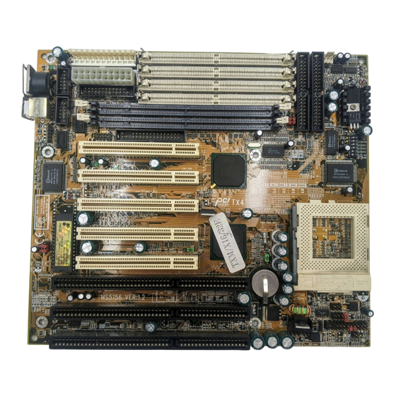
- Page 5 Three 16-Bit ISA SLOTs Five 32-Bit PCI SLOTs Two 168-Pin DIMM SOCKETs ATX 20-Pin POWER CONNECTOR ® PS/2 POWER CONNECTOR Four 72-pin SIMM SOCKETs ® Intel 82439TX ® Intel 82371AB SOCKET 7 2032 LITHIUM BATTERY...
- Page 6 ATKBD JIR1 Winbond JMS1 JRMS1 COM B COM A BIOS JPFAN FW82439TX FW82371AB JBAT1 BATT 3.3V 5V IDE2 JFAN 2 IDE1 JFAN 1 JRMS2 JSFAN JRMC1 JGS1 JGL1 JFP1 MS-5156...
-
Page 7: Hardware Installation
Chapter 2 HARDWARE INSTALLATION ® ® The MS-5156 mainboard operates with Intel Pentium processors/ ® ® Pentium processors with MMX technology, Cyrix 6x86/6x86L/ ® 6x86MX and AMD K5/K6 processors. It could operate with 2.8V to 3.52V processors. The mainboard provides a 321-pin ZIF Socket 7 for easy CPU installation, a DIP switch (SW1) to set the proper speed for the CPU and a Jumper block (JV2 - JV5) for setting the CPU voltage. - Page 8 2.1-2 CPU Voltage Setting: JV2-JV5 J V 2 J V 3 J V 4 J V 5 J V 2 J V 3 J V 4 J V 5 J V 2 J V 3 J V 4 J V 5 J V 2 J V 3 J V 4...
- Page 9 J V 2 J V 3 J V 4 J V 5 J V 2 J V 3 J V 4 J V 5 J V 2 J V 3 J V 4 J V 5 J V 2 J V 3 J V 4 J V 5 J V 2...
- Page 10 2.1-3 CPU Speed and Voltage Setting: SW1 & JV2-JV5 To adjust the speed and voltage of the CPU, you must know the specifica- tions of your CPU (always ask the vendor for CPU specifications). Then ® ® refer to Table 2.1 (Intel processors), Table 2.2 (Cyrix processors) and ®...
-
Page 11: Cpu Voltage
® Table 2.1 Intel processors ® ® Intel Pentium processors CPU Voltage CPU Speed CPU Type VI/O Vcore JV2~JV5 J V 2 3.38 J V 3 J V 4 J V 5 90MHz J V 2 3.52 J V 3 J V 4 J V 5 3.38... - Page 12 ® Table 2.2 Cyrix 6x86/6x86L/6x86MX processors ® Cyrix 6x86 processor uses PR to rate the speed of their processors based on Intel ® Pentium ® processor core speed. For example PR150 (120MHz) has 150MHz core speed of Intel ® Pentium ®...
- Page 13 ® Cyrix 6x86MX processors CPU Voltage CPU Speed CPU Type JV2~JV5 VI/O Vcore PR166 (60x2.5) (66x2) PR200 (66x2.5) (75x2) J V 2 J V 3 J V 4 PR233 J V 5 (66x3) (75x2.5) PR266 (66x3.5) (75x3) Note: PR200(75x2), PR233, and PR266 CPU are not yet tested, so we still don’t guarantee the performances of this CPUs.
- Page 14 ® Table 2.3 AMD K5/K6 processors ® K5/K6 CPU uses PR to rate the speed of their processors based on Intel ® CPU core speed . For example PR133(100MHz) has 133MHz core ® ® ® speed of Intel Pentium processor but has 100MHz core speed in AMD K5 CPU.
- Page 15 2.1-4 CPU Fan Power Connector: JFAN1/JFAN2/JSFAN/ JPFAN JFAN1 connector supports CPU cooling fan with +12V. It supports both two and three pin head connector. When connecting the wire to the connector, always take note that the red wire is the positive and should be connected to the +12V.
- Page 16 There are 5 PCI slots and 3 ISA slots. All PCI slots can be used as master. But since the 1st and 5th PCI slots share the same bus master signal, only one of these slots can be used as a master at a time; which means that if a bus master card is installed in PCI slot 1, PCI Slot 5 can only accomodate a slave card, and vice versa.
-
Page 17: Memory Bank Configuration
2.3-1 Memory Bank Configuration The mainboard provides four 72-pin SIMMs (Single In-Line Memory Module) and two 168-pin DIMM(Double In-Line Memory) sockets. It supports six memory banks for a maximum of 256MB memory. Each bank supports up to 64MB memory. You can use SIMM from 4MB, 8MB, 16MB, 32MB, 64MB to 128MB, and DIMM from 8MB, 16MB, 32MB, 64MB to 128MB. -
Page 18: Memory Installation Procedures
2.3-2 Memory Installation Procedures: A. How to install SIMM Module Notched Single Sided SIMM Double Sided SIMM 1. The SIMM slot has a “Plastic Safety Tab” and the SIMM memory module has a “Notched End”, so the SIMM memory module can only fit in one direction. - Page 19 B. How to install DIMM Module Single Sided DIMM Double Sided DIMM 1. The DIMM slot has two keys marked “VOLT and DRAM” , so the DIMM memory module can only fit in one direction. 2. Insert the DIMM memory module vertically into the DIMM slot. Then, push it in.
- Page 20 B.1 DIMM Power Voltage Selector: JV1 DIMM Voltage 3.3V SIMM Power Level : 5 Volts DIMM Power Level : 3.3V or 5V NOTE: DIMM and SIMM cannot be used at the same time. Only one kind can be used at a time. If you want to use both of them at the same time, you must use 5V DIMM.
-
Page 21: Memory Population Rules
2.3-3 Memory Population Rules 1. Make sure that the SIMM banks are using the same type and equal size density memory. 2. To operate properly, at least two 72-pin SIMM module must be installed in the same bank or one 168-pin DIMM module must be installed. The system cannot operate with only one 72-pin SIMM module. - Page 22 The Turbo LED, Turbo Switch, Hardware Reset, Key Lock, Power LED, Power Saving LED, Sleep Switch, Speaker and HDD LED are all grouped in JFP1 connector block for easy installation. JFP1 Speaker Power LED Keylock Power Saving HDD LED Turbo Switch Turbo LED Reset Switch Figure 2.1...
-
Page 23: Turbo Led
2.4-1 Turbo LED This mainboard is always on Turbo speed. Connecting a Turbo LED will just lit the LED. (See Figure 2.1) 2.4-2 Hardware Reset Reset switch are used to reboot the system rather than turning the power ON/OFF. Avoid rebooting the system when the HDD LED is lit. You can connect the Reset switch from the system case to this pin. - Page 24 The mainboard has two serial ports COM A and COM B. These two ports are 16550A fully compatible high speed communication ports that send/ receive 16 bytes FIFOs. You can attach a mouse or a modem cable directly into these connectors. COM B COM A 2-18...
- Page 25 The mainboard provides a connector for LPT. A parallel port is a standard printer port that also supports Enhanced Parallel Port(EPP) and Extended capabilities Parallel Port(ECP). 2-19...
- Page 26 The mainboard also provides a standard floppy disk connector, FDC that supports 360K, 720K, 1.2M, 1.44M and 2.88M floppy disk types. You can attach a floppy disk cable directly to this connector. 2-20...
- Page 27 The mainboard has a 32-bit Enhanced PCI IDE Controller that provides for two HDD connectors IDE1 (primary) and IDE2 (secondary). You can connect up to four hard disk drives, CD-ROM, 120MB Floppy (reserved for future BIOS) and other devices to IDE1 and IDE2. Secondary IDE Connector Primary IDE Connector IDE1(primary IDE connector)
-
Page 28: Pin Description Pin
® ® J9 is a standard 12-pin AT or PS/2 connector. Be sure to attach the connectors with the two black wires at the center. Power Connector Description Description Power Good Ground +5V DC Ground +12V DC -5V DC -12V DC +5V DC Ground +5V DC... - Page 29 This type of connector already supports the remote ON/OFF function. You don’t need to connect the JRMC1. However, you need to connect the Remote Power On/OFF switch (JRMS1 or JRMS2). Power Connector ATX Power Connector Pin Description -12V 3.3V PS_ON 5V_SB PW_OK 3.3V...
- Page 30 Connect to a 2-pin push button switch to JRMS1 or JRMS2. Every time the switch is shorted by pushing it once, the power supply will change its status from OFF to ON and ON to OFF. This is used for ATX type power supply. You can program this through BIOS.
- Page 31 Some PS/2 ® power supply support 3-pin remote power connector. This 3- pin connector should be connected to JRMC1, then use JRMS1 or JRMS2 to switch ON/OFF the system. JRMC1 PIN# Description 5V Standby ® Note: The pin definition of the PS/2 power supply remote power connector should be the same as shown above.
- Page 32 This jumper setting is used by ATX power supply without 3.3V, using ATX power supply with 3.3V or AT ® power supply should keep J10 open. POWER SUPPLY ATX w/o 3.3V ® ATX or AT 2-26...
- Page 33 ® The mainboard provides a standard AT keyboard DIN connector for attaching a keyboard. You can plug a keyboard cable directly to this connector. Pin5 Pin1 Pin2 Pin4 Pin3 DATA ® Keyboard Connector 2-27...
- Page 34 ® The mainboard provides a 5-pin connector for PS/2 mouse cable ® ® (optional). You can plug a PS/2 mouse to PS/2 mouse cable. The connector location as shown below. JMS1 Pin 1 Pin 2 Pin 3 Pin 4 Pin 5 DATA 2-28...
- Page 35 The mainboard provides a 5-pin infrared connector(IR) for IR module. This connector is for optional wireless transmitting and receiving infrared module. If you want to use this function, you must configure the setting through BIOS setup. GND RX JIR1 Note: This mainboard support SIR. 2-29...
- Page 36 Connect a USB cable to support USB device, such as keyboard and mouse. 2-30...
- Page 37 Attach a power saving switch to JGS1. When the switch is pressed, the system immediately goes into suspend mode. Press any key and the system wakes up. JGL1 can be connected with LED to monitor the JGS1. This will lit while the system is in suspend mode.
- Page 38 A battery must be used to retain the mainboard configuration in CMOS RAM. To retain the on-board battery you must always short pins 1,2 of JBAT1. JBAT1 (Default) Note: You can clear CMOS by shorting 2-3 pin, while the system is off. Then, return to 1-2 pin position.
- Page 39 This jumper is for setting the voltage of the Flash ROM BIOS. +12V (Default) (Reserved) 2-33...
-
Page 40: Award Bios Setup
® Chapter 3 AWARD BIOS SETUP ® Award’s BIOS ROM has a built-in Setup program that allows users to modify the basic system configuration. This type of information is stored in battery-backed RAM (CMOS RAM), so that it retains the Setup information when the power is turned off. -
Page 41: Status Page Setup Menu/Option Page Setup Menu
® Power on the computer and press <Del> immediately to allow you to enter Setup. The other way to enter Setup is to power on the computer. When the below message appears briefly at the bottom of the screen during the POST (Power On Self Test), press <Del>... - Page 42 ® Once you enter Award ® BIOS CMOS Setup Utility, the Main Menu (Figure 1) will appear on the screen. The Main Menu allows you to select from ten setup functions and two exit choices. Use arrow keys to select among the items and press <Enter>...
- Page 43 ® Standard CMOS Setup This setup page includes all the items in a standard compatible BIOS. BIOS Features Setup ® This setup page includes all the items of Award special enhanced features. Chipset Features Setup This setup page includes all the items of chipset special features. Power Management Setup This category determines the power consumption for system after setting the specified items.
- Page 44 ® The items in Standard CMOS Setup Menu are divided into 10 categories. Each category includes no, one or more than one setup items. Use the arrow keys to highlight the item and then use the <PgUp> or <PgDn> keys to select the value you want in each item. ROM PCI/ISA BIOS (2A59IM4A) STANDARD CMOS SETUP AWARD SOFTWARE, INC.
-
Page 45: Primarymaster/Primaryslave Secondarymaster/Secondary Slave
® Date The date format is <day><month> <date> <year>. Day of the week, from Sun to Sat, determined by BIOS. Read-only. month The month from Jan. through Dec. date The date from 1 to 31 can be keyed by numeric function keys. - Page 46 ® If the controller of HDD interface is ESDI, the selection shall be “Type 1”. If the controller of HDD interface is SCSI, the selection shall be “None”. If the controller of HDD interface is CD-ROM, the selection shall be “None”.
-
Page 47: Virus Warning
® ROM PCI/ISA BIOS (2A59IM4A) BIOS FEATURES SETUP AWARD SOFTWARE, INC. Virus Warning : Disabled Video BIOS Shadow :Enabled CPU Internal Cache : Enabled C8000-CBFFF Shadow :Disabled External Cache : Enabled CC000-CFFFF Shadow :Disabled Quick Power on Self Test : Disabled D0000-D3FFF Shadow :Disabled Boot Sequence... -
Page 48: Cpu Internal Cache
® Disabled No warning message to appear when anything (default) attempts to access the boot sector or hard disk partition table. Enabled Activates automatically when the system boots up causing a warning message to appear when anything attempts to access the boot sector of hard disk partition table. -
Page 49: Boot Sequence
® Boot Sequence This category determines which drive the computer searches first for the disk operating system (i.e., DOS). The settings are A,C,SCSI/ C,A,SCSI/C,CD-ROM,A/CD-ROM,C,A/D,A,SCSI/E,A,SCSI/F,A,SCSI/ SCSI,A,C/SCSI,C,A/C only. Default value is A,C,SCSI. Swap Floppy Drive Switches the floppy disk drives between being designated as A and B. -
Page 50: Typematic Rate Setting
® Gate A20 Option Normal The A20 signal is controlled by keyboard controller or chipset hardware. Fast(default) Default : Fast. The A20 signal is controlled by Port 92 or chipset specific method. Typematic Rate Setting This determines the typematic rate. Enabled Enable typematic rate and typematic delay programming. -
Page 51: Security Option
® Security Option This category allows you to limit access to the system and Setup, or just to Setup. System The system will not boot and access to Setup will be denied if the correct password is not entered at the prompt. Setup(default) The system will boot, but access to Setup will be denied if the correct password is not entered... -
Page 52: Video Bios Shadow
® Video BIOS Shadow Determines whether video BIOS will be copied to RAM for faster execution. Video shadow will increase the video performance. Enabled (default) Video shadow is enabled Disabled Video shadow is disabled C8000 - CFFFF Shadow/E8000 - EFFFF Shadow Determines whether the optional ROM will be copied to RAM for faster execution. - Page 53 ® The Chipset Features Setup option is used to change the values of the chipset registers. These registers control most of the system options in the computer. Choose the “CHIPSET FEATURES SETUP” from the Main Menu and the following screen will appear. ROM PCI/ISA BIOS(2A59IM4A) CMOS SETUP UTILITY CHIPSET FEATURES SETUP...
-
Page 54: Auto Configuration
® Auto Configuration Choosing Enabled (default) will automatically configure chipset features using default settings. Choose Disable to customize setup. DRAM Timing Sets the DRAM speed at 70ns (default) or 60ns. It will set the speed of the EDO/FP DRAM. DRAM Leadoff Timing To be able to change the setting, Auto configuration must be disable. - Page 55 ® Fast EDO Lead Off Under Auto config. the BIOS will identify which type of DRAM is being used. Choose the setting accordingly. To customize, use this option. Choose Enable or Disable. If the system is using EDO DRAM, choose enable.
- Page 56 ® SDRAM Speculative Read The settings are enable or disable. If you only use One Bank for SDRAM and there’s no EDO or FP mix together, the setting is Enable. If two banks are used by SDRAM, it will automatically be set to disable. The default setting is enable.
-
Page 57: Power Management
® The Power Management Setup will appear on your screen like this: ROM PCI/ISA BIOS (2A59IM4A) POWER MANAGEMENT SETUP AWARD SOFTWARE, INC. ** Reload Global Timer Events ** Power Management :User Define IRQ [3-7,9-15],NMI : Enabled PM Control by APM :Yes Primary IDE 0 : Enabled... -
Page 58: Pm Control By Apm
® Power Management Disable Global Power Management will be disabled. User Define Users can configure their own power management. Min Saving Pre-defined timer values are used such that all timers are in their MAX value. Max Saving Pre-defined timer values are used such that all timers are in their MIN value. -
Page 59: Video Off After
® Video Off After The settings are N/A, Standby, Doze, or Suspend. This option is for choosing the setting in which the monitor will turn off. Always turn on. Doze During Doze mode, the monitor will be turned off. Standby During Standby mode, the monitor will be turned off. Suspend During Suspend mode, the monitor will be turned off. -
Page 60: Throttle Duty Cycle
® Suspend Mode Disable System will never enter SUSPEND mode. Defines the continuous idle time before the 1 Min/2 Min/ system enters SUSPEND mode. 4 Min/6 Min/ If any item defined in the options of “Power 8 Min/10 Min/ Down & Resume Events” is enabled & active, 20 Min/30 Min/ SUSPEND timer will be reloaded. -
Page 61: Soft-Off By Pwr-Bttn
® Soft-Off by PWR-BTTN The settings are Delay 4 sec or Instant-off. During Delay 4 sec, if you push the switch one time, the system goes into suspend mode and if you push it more than 4 second, the system will be turned off. During instant-off, the system will turn off once you push the switch. - Page 62 ® IRQ 8 Clock Event IRQ[3-7,9-15], NMI : Enabled Primary IDE 0 : Enabled Primary IDE 1 : Disabled Secondary IDE 0 : Disabled Secondary IDE 1 : Disabled Floppy Disk : Enabled Serial Port : Enabled Parallel Port : Enabled During Enabled, if any interrupt event occurs, the system will wake- up from suspend mode.
-
Page 63: Pnp Os Installed
® You can manually configure the PCI Device’s IRQ. The following pages tell you the options of each item & describe the meanings of each options. ROM PCI/ISA BIOS (2A69HM4D) PNP/PCI CONFIGURATION SETUP AWARD SOFTWARE, INC. PCI IDE IRQ Map To : PCI-Auto PnP OS Installed Primary IDE INT#... -
Page 64: Resources Controlled By
® Resources Controlled By By Choosing “Auto”, the system BIOS will detect the system resource and automatically assign the relative IRQ and DMA Channel for each peripheral. By Choosing “Manual”(default), the user will need to assign IRQ & DMA for add-on cards. Be sure that there is no conflict for IRQ/DMA and I/ O ports. - Page 65 ® IRQ-15 assigned to : PCI/ISA PnP DMA-0 assigned to : PCI/ISA PnP DMA-1 assigned to : PCI/ISA PnP DMA-3 assigned to : PCI/ISA PnP DMA-5 assigned to : PCI/ISA PnP DMA-6 assigned to : PCI/ISA PnP DMA-7 assigned to : PCI/ISA PnP The above settings will be shown on the screen only if “Manual”...
-
Page 66: Assign Irq For Vga
® Assign IRQ for VGA Lets the user choose which IRQ to assign for VGA card. Used MEM base addr Lets the user choose the Legacy ISA addr. The settings are NA#, C800, CC00, D000, D400, D800 OR DC00. Used MEM Length Choose 8K, 16K, 32K, or 64K MEM length for the MEM used by the Legacy ISA address. -
Page 67: Ide Hdd Block Mode
® ROM PCI/ISA BIOS (2A69HM4D) INTEGRATED PERIPHERALS AWARD SOFTWARE, INC. Onboard Parallel Mode :ECP/EPP IDE HDD Block Mode :Enabled ECP Mode Use DMA IDE Primary Master PIO :Auto Parallel Port EPP Type :EPP1 IDE Primary Slave PIO :Auto IDE Secondary Master PIO :Auto IDE Secondary Slave PIO :Auto IDE Primary Master UDMA... - Page 68 ® IDE Secondary Slave PIO Auto/Mode0/Mode1-4 For these 4 IDE options, choose “Auto” to have the system BIOS auto detect the IDE HDD operation mode for PIO access. Note: Some IDE HDD can not operate at the responding HDD’s mode. When the user has selected “Auto”...
-
Page 69: Onboard Serial Port 1
® PCI Slot IDE 2nd Channel Enabled/Disabled Choosing Enabled will allow the system to access the 2nd IDE channel without a device driver. If the Off-Board PCI IDE add-on card is installed, the 2nd IDE channel will need to be used. Onboard FDD Controller Enabled/Disabled The system has an on-board Super I/O... -
Page 70: Uart 2 Mode
® UART 2 MODE Standard/ASKIR/ The system’s built-in IR (Infrared) is on the on-board Super I/O chipset and it shares serial port 2 with UART 2. Only one option can be selected for serial port 2, either the IR or UART. Selecting the IR mode will prompt the following message: IR Function Duplex... -
Page 71: Onboard Parallel Mode
® Onboard Parallel Mode SPP : Standard Parallel Port EPP : Enhanced Parallel Port ECP : Extended Capability Port To operate the onboard parallel port as SPP/(EPP/SPP)/ StandardParallel Port only, choose ECP(ECP/EPP) “SPP.” To operate the onboard parallel port in the ECP and SPP modes simulta- neously choose “ECP/SPP.”... - Page 72 ® This Main Menu item lets you configure the system so that a password is required each time the system boots or an attempt is made to enter the Setup program. Supervisor Password allows you to change all CMOS settings but the User Password setting doesn’t have this function. The way to set up the passwords for both Supervisor and User are as follow: 1.
- Page 73 ® You can use this utility to automatically detect the characteristics of most hard drives. When you enter this utility, the screen asks you to select a specific hard disk for Primary Master. If you accept a hard disk detected by the BIOS, you can enter “Y”...
- Page 74 ® Chapter 4 ® BIOS USER GUIDE The system configuration information and chipset register information is stored in the CMOS RAM. This information is retained by a battery when the power is off. Enter the BIOS setup (if need) to modify this information. The following pages will describe how to enter BIOS setup, and all about options.
-
Page 75: Enter Bios Setup
® 4.1 Enter BIOS Setup Enter the AMI ® setup Program’s Main Menu as follows: 1. Turn on or reboot the system. The following screen appears with a series of diagnostic check. AMIBIOS (C) 1996 American Megatrends Inc. Hit <DEL> if you want to run setup (C) American Megatrends Inc. - Page 76 ® AMIBIOS HIFLEX SETUP UTILITIES - VERSION 1.07 (C) 1996 American Megatrends, Inc. All Rights Reserved Standard CMOS Setup Advanced CMOS Setup Advanced Chipset Setup Power Management Setup PCI/Plug and Play Setup Peripheral Setup Hardware Monitor Setup Auto-Detect Hard Disks Change User Password Change Supervisor Password Auto Configuration with Optimal Settings...
-
Page 77: Standard Cmos Setup
® 4.2 Standard CMOS Setup 1. Press <ENTER> on “Standard CMOS Setup” of the main menu screen . AMIBIOS SETUP - STANDARD CMOS SETUP (C)1996 American Megatrends,Inc.All Rights Reserved Date (mm/dd/yyyy): Fri June 20, 1997 Time (hh/mm/ss): 17:09:25 Floppy Drive A: 1.44 MB 3 1/2 Floppy Drive B: Not Installed... -
Page 78: Advanced Cmos Setup
® 4.3 Advanced CMOS Setup 1. Press <ENTER> on “Advanced CMOS Setup” of the main menu AMIBIOS SETUP - ADVANCED CMOS SETUP (C) 1996 American Megatrends, Inc. All Rights Reserved Available Options: Ist Boot Device FLOPPY 2nd Boot Device IDE-0 Enabled 3rd Boot Device CD-ROM... -
Page 79: Quick Boot
® Description of the item on screen follows: 1st Boot Device/2nd Boot Device/3rd Boot Device/ 4th Boot Device This option sets the sequence of boot drives. The settings are: IDE0 The system will boot from the first HDD. IDE1 The system will boot from the Second HDD. IDE2 The system will boot from the Third HDD. -
Page 80: Primary Display
® Floppy Access Control This option sets the Floppy to Read-only or Normal(Full Access). HDD Access Control This option sets the HDD to Read-only or Normal(Full Access). During Read-only, if you try to write on the HDD the system will halt. PS/2 ®... -
Page 81: System Bios Cacheable
® System BIOS Cacheable ® BIOS always copies the system BIOS from ROM to RAM for faster execution. Set this option to Enabled to permit the contents of the F0000h RAM memory segment to be written to and read from cache memory. The settings are Enabled or Disabled. -
Page 82: Advanced Chipset Setup
® 4.4 Advanced Chipset Setup 1. Press <ENTER> on “Advanced Chipset Setup” of the main menu screen. AMIBIOS SETUP - ADVANCED CHIPSET SETUP (C) 1996 American Megatrends, Inc. All Rights Reserved Memory Hole Disabled Available Options: DRAM Speed Auto Enabled Fast MA to RAS# Delay (HCLK’s) Disabled DRAM Read Burst Timing... - Page 83 ® Description of the item on screen follows: Memory Hole Choosing Enabled, will enable a memory hole in the DRAM space. The CPU cycle matching the enabled hole will be passed on the PCI. PCI cycles matching an Enabled hole are ignored. Disabled(default) will disable this function.
- Page 84 ® Speculative Lead Off Timing Leave on the default setting of Disabled. DRAM Page Idle Timeout (HCLK’s) Leave on the default setting of 2. Fast EDO Read Cycle Timing Leave on the default setting of Disabled. SDRAM Speculative Read Logic Leave on the default setting of Disabled.
-
Page 85: Read Around Write
® USWC Write Posting Set this option to Enabled to use USWC(Uncacheable, Speculatable, Write-Combined) memory. The settings are Enabled or Disabled. The Optimal and Fail-Safe default settings are Disable. CPU To PCI Posting Set this option to Enabled to give priority to posted messages from the CPU to the PCI bus. -
Page 86: Power Management Setup
® 4.5 Power Management Setup 1. Press <ENTER> on “Power Management Setup” of the main menu screen. AMIBIOS SETUP - POWER MANAGEMENT SETUP (C) 1996 American Megatrends, Inc. All Rights Reserved Power Management / APM Disabled Available Options: Instant On Support Disabled Enabled Green PC Monitor Power State... -
Page 87: Video Power Down Mode
® Description of the item on screen follows: Power Management/APM ® Set this option to Enabled to enable the Intel 82371AB ISA power management features and APM(Advanced Power Management). The settings are Enabled, Inst-On(instant-on) or Disabled. The Optimal and Fail- Safe default settings are Disabled. -
Page 88: Standby Timeout (Minute)
® Standby Timeout (Minute) This option specifies the length of a period of system inactivity while in Full power on state. When this length of time expires, the computer enters Standby power state. The settings are Disabled, 1 min, 2 min, 3 min, 4 min, 5 min, 6 min, 7 min, 8 min, 9 min, 10 min, 11 min, 12 min, 13 min, 14 min or 15 min. -
Page 89: Modem Use Irq
® Modem Use IRQ This indicates which IRQ no. will be used by the MODEM (if there is a MODEM). THe settings are 3, 4, 5 ,7 ,9, 10, or N/A. Soft-Off by PWR-BTTN The settings are Delay 4 sec or Instant-off. During Delay 4 sec, if you push the switch one time the system goes into suspend mode and if you push it more than 4 second the system tunr off. -
Page 90: Pci/Plug And Play Setup
® 4.6 PCI/Plug and Play Setup 1. Press <ENTER> on “PCI/Plug and Play Setup” of the main menu screen. AMIBIOS SETUP - PCI/PLUG AND PLAY SETUP (C) 1996 American Megatrends, Inc. All Rights Reserved Available Options: Plug and Play Aware O/S Enabled Clear NVRAM Disabled... -
Page 91: Plug And Play Aware O/S
® Description of the item on screen follows: Plug and Play Aware O/S Set this option to Yes if the operating system in this computer is aware of and follows the Plug and Play specification. Currently, only ® Windows 95 is PnP-aware. The settings are Yes or No. The Optimal and Fail-Safe default settings No. -
Page 92: Pci Ide Busmaster
® PCI IDE BusMaster Set this option to Enabled to specify that the IDE controller on the PCI local bus includes a bus mastering capability. The settings are Enabled or Disabled. The Optimal and Fail-Safe default settings are Disabled. Offboard PCI IDE Card This option specifies if an offboard PCI IDE controller adapter card is installed in the computer. - Page 93 ® DMA Channel 0/DMA Channel 1/DMA Channel 3/DMA Channel 5/DMA Channel 6/DMA Channel 7 These options specify the bus that the specified DMA channel is used. These options allow you to reserve DMAs for legacy ISA adapter cards. These options determine if AMI ®...
-
Page 94: Peripheral Setup
® 4.7 Peripheral Setup 1. Press <ENTER> on “Peripheral Setup” of the main menu screen. AMIBIOS SETUP - PERIPHERAL SETUP (C) 1996 American Megatrends, Inc. All Rights Reserved Available Options: OnBoard FDC Enabled Enabled OnBoard Serial PortA Enabled Disabled OnBoard Serial PortB Enabled IR Port Support Disabled... -
Page 95: Onboard Fdc
® Description of the item on screen follows: Onboard FDC Choose Auto, for the BIOS to automatically detect the device If the ISA add-on card has Onboard FDC to be set at Disabled FDC exist Enabled none FDC exist Choose Enabled, Enabling onboard FDC. Choose Disabled, Disabling onboard FDC. -
Page 96: Onboard Parallel Port
® IR Port Support(leave on the default setting of Disabled) Onboard Parallel Port Choose Auto, the BIOS automatically assigned onboard parallel port to available parallel port or disabled If the ISA add-on card has Onboard parallel port LPT1 LPT2 LPT3 PORT I/O:378H I/O:278H... -
Page 97: Parallel Port Irq
® Parallel Port IRQ If the onboard parallel mode is not on auto mode, the user can select the interrupt line for onboard parallel port. We suggest that the user select the interrupt for the onboard parallel port as shown below: Onboard parallel port set at Parallel Port IRQ LPT1(378H)
Need help?
Do you have a question about the MS-5156 and is the answer not in the manual?
Questions and answers