XIEGU X108G Service Manual
Hide thumbs
Also See for X108G:
- Operating manual (18 pages) ,
- Operating instructions manual (15 pages) ,
- Service manual (36 pages)
Table of Contents
Advertisement
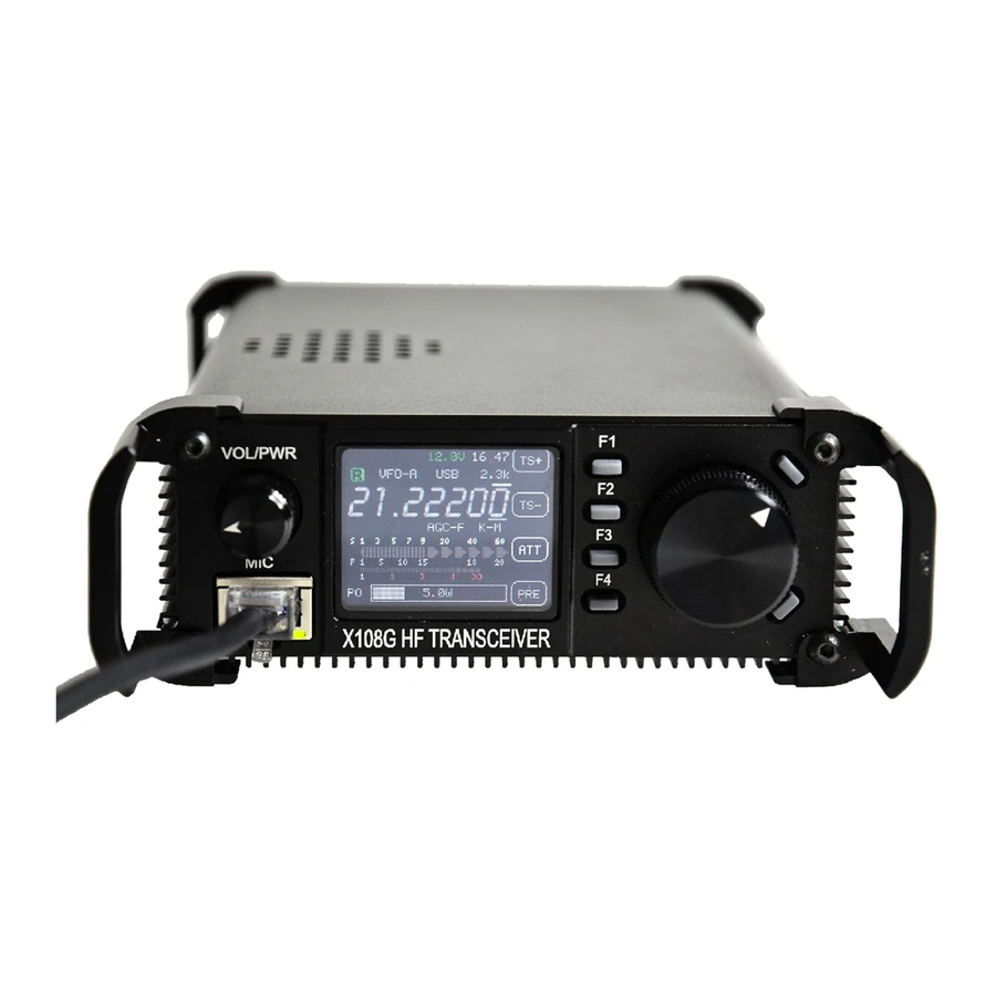
HF TRANSCEIVER
X108G
SERVICE MANUAL
VERSION: 1.00.0
Copyright © 2010~2017, Xiegu Communications
【Important Notes】
Before disassembling, make sure that the problem comes from inside the
transceiver.
Be sure to completely cut off the external power before opening case.
Do not forcibly remove any parts to avoid any damage.
Please use insulated screwdriver to adjust the circuit to avoid short circuit.
Do not turn on the radio for a long time if there is any fault.
Do not connect the transmit port directly to the test ports of signal generator
or network analyzer.
Do not keep transmitting in open circuit status for repairing.
Read the manual carefully before doing any test.
XIEGU COMMUNICATIONS
Advertisement
Table of Contents

Related Manuals for XIEGU X108G


Summary of Contents for XIEGU X108G
- Page 1 Do not connect the transmit port directly to the test ports of signal generator or network analyzer. Do not keep transmitting in open circuit status for repairing. Read the manual carefully before doing any test. VERSION: 1.00.0 Copyright © 2010~2017, Xiegu Communications...
- Page 2 Part 1 Technical Specs Basic specs: Frequency range: 0.5~30MHz All ham band Operate mode: SSB(J3E) CW (A1A) AM (A3E) Min freq. Step: Antenna impedance: 50Ω Operating temperature range: -10℃ ~ +60℃ Frequency stability: ±0.5ppm @ Power on 5mins, -10℃~+60℃ Operating voltage: 12~14.5V DC Current parameter: 700mA @Max...
- Page 3 Part 2 Inside Circuit Small signal front panel Microprocessor Mic amplifier gain adjustment Intermediate frequency amplifier unit Transmit Mixer Receive Mixer...
- Page 4 Small signal back panel Local oscillator module BPF module 功放电源板正面...
- Page 5 U17B VC Voice Compressor Steady voltage power Final RF power amplifier Power standing wave detector...
- Page 6 Part 3 Circuit principle 3.1 Receiving Circuit outputs to intermediate frequency crystal filter(IFCF) by T5. Q6 is NB control switch which controls the 3.1.1 RF front-end circuit conducting of the Q21. The RF front-end circuit of 0.5--30MH is composed of a Receiving band-pass filter, receiving preamplifier, pre 3.1.4 IFCF sets attenuator.
- Page 7 The demodulation of AM mode is accomplished by D2 3.2.2 Modulator circuit and its peripheral circuit. The microphone amplified signal enters the modulator U6 via the audio switch U27 to do SSB modulation. AM modulator circuit consists of U6, Q10, D3, D8 and so on, to restore carrier and modulate.
- Page 8 3.3.2 External interface circuit unit and U3B, U4B and U9B control the band switching. X108G has the following external interfaces: AUX, KEYER, ACC, SPK, Micro-USB. Micro-USB is the real USB connector and it connects to the processor U17.
- Page 9 The band voltage generator consists of microprocessor and U25 and U26. 3.4 Power unit There are 2 groups main power supply for X108G, 9V and 5V, which are generated by U1B (LM2940T-9.0) and U2B (LM7805) on the power amplifier board. The microprocessor requirs 3.3V voltage which is generated by the U19.
- Page 10 X-axis:1ms, the units on the Y-axis:100mV Note: During the test, do not turn-on the X108G to transmit, otherwise the RF signal source will be damaged! Set the receiving frequency of X108G to be 14.25000MHz, [USB] mode.
- Page 11 Open [PRE],close [ATT] and [AGC] and [SQL]. Connect the SPK interface to input port of audio analyzer. adjust the volume of the X108G to make the amplitude of the signal measured by the audio analyzer is 2000mV. 5) Set the RF signal source output amplitude to be 0.35uV, and the SINAD test value of the audio analyzer...
- Page 12 Digital multimeter DC voltage test Note: During the test, do not turn-on the X108G to transmit, otherwise the RF signal source will be damaged! Set the receiving frequency of X108G to be 14.25000MHz, [USB] mode. Open [PRE],close [ATT] and [AGC] and [SQL].
- Page 13 Set the receiving frequency of X108G to be 14.25000MHz, [USB] mode. Open [PRE],close [ATT] and [AGC] and [SQL]. Connect the output port of the RF signal source to the antenna interface of the X108G; Turn off the RF signal source output, adjust the S table reference voltage PotentiometerRW1, make the -121dBm value of ADC on the screen is 2500, press the [SET] button to enter the next level signal setting.
- Page 14 Frequency:1kHz Amplitude:100mV-Vpp 50W RF load Set the receiving frequency of X108G to be 14.25000MHz, [USB] mode. Connect the RF load to the antenna port of the X108G. Unplug the TX signal line from small signal board to the power amplifier board.
- Page 15 The output signal of the audio signal source is connected to a special test microphone,and open the output of the audio signal source. Press the PTT of speaker microphone to start the X108G transmitting, and observe the carrier output power measured by the spectrum analyzer.
- Page 16 Central frequency:14.25MHz BW:5MHz 50W RF load Set the receiving frequency of X108G to be 14.25000MHz, [CW] mode,power 20W Connect the RF load to the antenna interface of the X108G. Press the CW key to start the transmit, measure G2 voltage of the transmitting amplifier Q3 by digital multimeter.
- Page 17 DC voltage test gear 50W RF load Set the receiving frequency of X108G to be 14.25000MHz, [USB] mode. Unplug the TX signal line from small signal board to the power amplifier board. Connect the RF load to the antenna interface of the X108G.
- Page 18 Part 5 Parts List Power amplifier board Item SPECS PACKAGE BRAND Designator Aluminum C1B, C2B, C7B, C8B, C90B, C110B, Würth 875105359010 100uF solid cap C113B C3B, C4B, C5B, C6B, C40B, C45B, C46B, C56B, C59B, C60B, C61B, C62B, C66B, C67B, C68B, C69B, C70B, C73B, C74B, C75B, C76B, C77B, C81B, C82B, Murata capacitor...
- Page 19 Murata capacitor 22pF 0805 GRM21A5C2D220JW01 C134B Murata capacitor 82pF 0805 GRM21A5C2D820JW01 C138B Schottky Toshiba 1SS372 SC-70 1SS372 D1B, D2B diode Changjiang Zener diode SOD-323 BZT52C10V0S D3B, D4B, D16B Electronic diode 1N4007 DO-214AC domestic Changjiang Zener diode 5.1V SOD-323 BZT52C5V1S Electronic D7B, D8B, D9B, D10B, D11B, D12B, diode 1N4148...
- Page 20 FDS4435BZ SO-8 FAIRCHILD FDS4435BZ Q6B, Q8B RF FET BC868 SOT-89 Philips BC868 IRLML5203PBF SOT-23 IRLML5203PBF Q9B, Q10B Digital triode DTC114EKA SOT-23 ROHM DTC114EKA Resistance 1206 Yageo RC1206FR-0751R R1B, R2B Resistance 330R 0603 Yageo RC0603FR-07330R R3B, R15B, R17B Resistance 330R 1812 Yageo RC1812FR-07330R R4B, R11B...
- Page 21 transformer common mode Through-Hole domestic custom made inductance common Würth mode 744253200 744253200 T5B, T6B inductance Integrated LM2940T-9.0 TO-220 LM2940T-9.0 circuit Integrated L7805CV TO-220 L7805CV circuit Integrated 74HC238PW TSSOP-16 74HC238PW U3B, U9B circuit Integrated ULN2004D SO-16 ULN2004D circuit Integrated LM358PW TSSOP-8 LM358PW circuit...
- Page 22 Resistance 0603 Yageo RC0603FR-0710K Resistance 1.2M 0603 Yageo RC0603FR-071M2 Resistance 0603 Yageo RC0603FR-0715K Resistance 1.2k 0603 Yageo RC0603FR-071K2 Exclusion 8P4R Yageo YC164-JR0710K RP1, RP2 MC34063EBD SO-8 MC34063EBD Local vibration board Item SPECS PACKAGE BRAND Designator C1, C2, C3, C4, C5, C6, C7, C8, C9, C10, C11, C12, C15, C16, C18, C19, C22, Murata...
- Page 23 TCXO 26MHz DSB321SDN 3225 26MHz DSB321SDN Through-H Ceramic filter TDK107MS180K TDK107MS180K Small signal board Item SPECS PACKAGE BRAND Designator Button type MS920SE FL27E Seiko MS920SE FL27E lithium battery C1, C2, C4, C6, C7, C11, C12, C13, C14, C15, C16, C19, C24, C25, C29, C30, C33, C34, C35, C37, C38, C39, C40, C44, C45, C47, C50, C55, C56, C57, C58, C62, C63, C64, C65, C67,...
- Page 24 Murata Capacitance 33pF 0603 GRM1885C2A330JA01 C31, C32 Aluminum solid Würth 330uF 875115350004 C43, C160 Capacitance Murata Capacitance 47nF 0603 GRM188R71H473KA61 Aluminum solid Würth 47uF 875105359006 C54, C169, C190 Capacitance Murata Capacitance 22pF 0402 GRM1552C2A220GA01 C86, C89 Murata Capacitance 12pF 0603 GRM1885C2A120JA01 C116 Murata...
- Page 25 L3, L4, L5, L6, L7, L13, L19, Winding L20, L22, L26, L27, L30, L32, 100uH 0805 GLF2012T101K inductance L35, L37, L38, L39, L43, L44, L47, L48, L49, L50 Winding 10uH 0805 GLF2012T100K inductance Winding Würth 470uH 1210 744032471 inductance Winding L21, L23, L24, L25, L28, L29, 0805 GLF2012T1R0M...
- Page 26 R4, R20, R39, R40, R53, R64, R65, R71, R82, R108, R121, R122, R127, R132, R134, Resistance 100R 0603 Yageo RC0603FR-07100R R137, R150, R154, R181, R184, R187, R190, R196, R197 Resistance 0603 Yageo RC0603FR-0715K R6, R9, R10, R41, R63, R72, R88, R109, R118, R119, R120, R126, R135, R136, Resistance 0603...
- Page 27 Resistance 5.1k 0603 Yageo RC0603FR-075K1 R83, R102, R186 Resistance 220R 0603 Yageo RC0603FR-07220R Resistance 0603 Yageo RC0603FR-0733K R110, R145, R163, R164 Resistance 680R 0603 Yageo R111, R165 Resistance 0603 Yageo RC0603FR-0720K R133, R183 Resistance 0603 Yageo RC0603FR-0768K R143 Resistance 330R 0603 Yageo RC0603FR-07330R...
- Page 28 Crystal 32.768kHz 3215-2PIN EPSON oscillator Crystal filter SUNNY Xiegu module 80m/160m module Xiegu XGM1 Xiegu module 40m/60m module Xiegu XGM2 Xiegu module 20m/30m module Xiegu XGM3 Xiegu module 15m/17m module Xiegu XGM4 Xiegu module 10m/12m module Xiegu XGM5 Xiegu module...
- Page 29 Part 6 Small signal board...
- Page 30 Small signal board BOTT...
- Page 31 AMP Power board...
- Page 32 AMP Power board BOTT...
- Page 33 Part 7 Radio block diagram...
- Page 34 Part 8 Circuit Schematic...
- Page 36 XIEGU COMMUNICATIONS 无线科技,无限创造 WWW.CQXIEGU.COM...
Need help?
Do you have a question about the X108G and is the answer not in the manual?
Questions and answers