Table of Contents
Advertisement
Available languages
Available languages
Quick Links
Advertisement
Chapters
Table of Contents

Related Manuals for Prolight LUMA700


Summary of Contents for Prolight LUMA700
- Page 1 LUMA700 MOVING HEAD MANUALE UTENTE USER MANUAL IT - EN...
- Page 2 Music & Lights S.r.l. si riserva ogni diritto di elaborazione in qualsiasi forma delle presenti istruzioni per l’uso. La riproduzione - anche parziale - per propri scopi commerciali è vietata. Al fine di migliorare la qualità dei prodotti, la Music&Lights S.r.l. si riserva la facoltà di modificare, in qualunque momento e senza preavviso, le specifiche menzionate nel presente manuale di istruzioni.
-
Page 3: Table Of Contents
3. 22 Funzioni avanzate 3. 23 Informazioni sul dispositivo 4 Manutenzione 4. 1 Manutenzione e pulizia del sistema ottico 4. 2 Sostituzione fusibile 4. 3 Risoluzione dei problemi Certificato di garanzia Contenuto dell'imballo: • LUMA700 • Staffa di fissaggio • Manuale utente... -
Page 4: Sicurezza
LUMA700 ATTENZIONE! Prima di effettuare qualsiasi operazione con l’unità, leggere con attenzione questo manuale e conservarlo accuratamente per riferimenti futuri. Contiene informazioni importanti riguardo l’installazione, l’uso e la manutenzione dell’unità. SICUREZZA Avvertenze generali • I prodotti a cui questo manuale si riferisce sono conformi alle Direttive della Comunità Europea e per- tanto recano la sigla . -
Page 5: Informazioni Generali
LUMA700 INFORMAZIONI GENERALI Spedizioni e reclami Le merci sono vendute “franco nostra sede” e viaggiano sempre a rischio e pericolo del distributore/clien- te. Eventuali avarie e danni dovranno essere contestati al vettore. Ogni reclamo per imballi manomessi dovrà essere inoltrato entro 8 giorni dal ricevimento della merce. -
Page 6: Introduzione
LUMA700 - 1 - INTRODUZIONE 1.1 DESCRIZIONE LUMA 700 è il nuovo concept di sagomatore LED capace di sostituire un dispositivo con lampada a scarica tradizionale da 700w. Il brillante LED, il fascio variabile nel range 5°-50°, l’enorme quantità di palette colori e il definito sistema colore CMY, rendono LUMA 700 un cavallo di battaglia del mondo del lighting. - Page 7 LUMA700 • Iris motorizzato lineare 5-100% Elettronica • Display LCD a colori ad alta risoluzione per accesso semplificato al menu di controllo, configurazione e assegnazione indirizzo • Menu disponibile in lingua Inglese, francese, spagnolo • 4 configurazioni DMX disponibili: 21/23/30/31 canali per ampia flessibilità di controllo • WDMX: Ricevitore ad antenna (2.4 GHz) by Wireless Solution Sweden (incluso)
- Page 8 LUMA700 Disegno tecnico 5°- 50° 2.5m 80420/3566lx 0.28/2.2m 5.0m 19950/1008lx 0.56/4.4m 7.5m 8986/500lx 0.84/6.6m 10.0m 5105/330lx 1.11/8.8m Lux Center Beam Angle: 5°- 50° Beam Width Diagramma di luminosità Fig.1...
-
Page 9: Elementi Di Comando E Di Collegamento
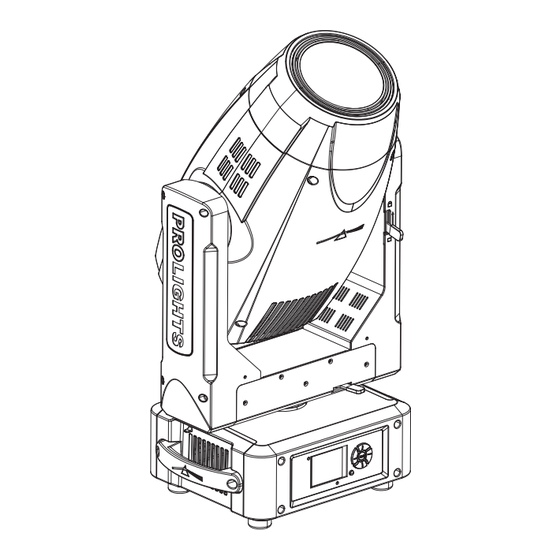
LUMA700 1.3 ELEMENTI DI COMANDO E DI COLLEGAMENTO 1. TESTA MOBILE 2. BRACCIO GIREVOLE 3. BLOCCO E SBLOCCO MOVIMENTO TILT 4. BLOCCO E SBLOCCO MOVIMENTO 5. MANIGLIA PER TRASPORTO 6. INDICATORE LED "WDMX" 7. MICROFONO 8. PANNELLO DI CONTROLLO con... -
Page 10: Installazione
- 2 - INSTALLAZIONE 2.1 MONTAGGIO Il LUMA700 può essere collocato su un piano solido. Inoltre, grazie ai fori di fissaggio, l’unità può essere montata anche a testa in giù, su una traversa (fig.3). Per il fissaggio occorrono dei supporti robusti per il montaggio. -
Page 11: Funzioni E Impostazioni
60Hz). La testa mobile e tutti i motori di comando si mettono in una precisa posizione di partenza. Poco dopo l’unità è pronta. Per spegnere il LUMA700, staccare la spina dalla presa di rete. Per maggiore como- dità è consigliabile collegare l’unità con una presa comandata da un interruttore. -
Page 12: Utilizzo Del Menu
LUMA700 3.3 UTILIZZO DEL MENU 1. Premere il tasto ENTER per accedere al menu principale. 2. Con i tasti UP/DOWN selezionare il menu su cui si desidera operare: • Connect; • Setup; • Advanced; • Information; • Stand alone; 3. Premere il tasto ENTER per visualizzare la prima voce del menu selezionato. -
Page 13: Struttura Menu
LUMA700 3.4 STRUTTURA MENU MENU ð ð ð CONNECT Address Value (1-512) ð W-DMX Value (1-512) ð ð DMX Mode Mode Standard/Extended/ Basic-8bit/Basic-16bit/User ð Edit User Max Channel/Control/Pan/Pan Fine/Tilt/... ð ð Wireless DMX Out ON/OFF ð Reset Connect YES/NO ð... - Page 14 LUMA700 ð ð ADVANCED Reset Pan & Tilt Colors Gobos Others ð ð Calibration Password 050 (unlocks the following settings) ð Value (-128-127) ð Tilt Value (-128-127) ð Color1 Value (-128-127) ð Gobo1 Value (-128-127) ð Prism Value (-128-127) ð...
-
Page 15: Modalità Slave Receive
Sull’unità master selezionare il programma desiderato come indicato al paragrafo 3.6. Servirsi dei connettori DMX del LUMA700 e di un cavo XLR per formare una catena di unità. In certe condi- zioni e lunghezze si consiglia di effettuare una terminazione come mostrato a pagina 20. -
Page 16: Modalità Scenes Record
• Premere il tasto LEFT più volte per uscire dal menu e per salvare le modifiche apportate. 3.7 MODALITÀ SCENES RECORD LUMA700 è dotato di un registratore DMX integrato attraverso il quale è possibile trasmettere, dal vostro Controller DMX al dispositivo, le scene programmate. Procedere come segue per memorizzare la sequenza di scene da mandare in esecuzione. -
Page 17: Modalità Musicale
LUMA700 ENTER per accedere al menu successivo. • Premere il tasto UP/DOWN per selezionare Scenes Record e premere il tasto ENTER per accedere al menu successivo. • Premere il tasto UP/DOWN per regolare la scena di inizio e quella di fine da inserire nel programma automatico, quindi premere il tasto ENTER per confermare. -
Page 18: Modalità Dmx
• Premere il tasto LEFT più volte per uscire dal menu e per salvare le modifiche apportate. 3.12 CONFIGURAZIONI CANALI DMX LUMA700 dispone di 5 configurazioni dei canali DMX a cui si può accedere dal pannello di controllo. • Premere il tasto ENTER per accedere al menu principale. - Page 19 LUMA700 DMX Address: 33 DMX Address: 54 DMX Address: 75 DMX Address: 96 ... . DMX512 Controller Fig.6 - Esempio di configurazione a 21 canali DMX...
-
Page 20: Collegamenti Della Linea Dmx
LUMA700 3.14 COLLEGAMENTI DELLA LINEA DMX La connessione DMX è realizzata con connettori standard XLR. Utilizzare cavi schermati, 2 poli ritorti, con impedenza 120Ω e bassa capacità. Per il collegamento fare riferimento allo schema di connessione riportato di seguito: DMX - INPUT... -
Page 21: Canali Dmx
LUMA700 3.16 CANALI DMX BAS-8 BAS-16 STD FUNCTION Value 19 Ch 21 Ch 28 Ch 29 Ch 0~100% 000 - 255 PAN FINE 0~100% 000 - 255 TILT 0~100% 000 - 255 TILT FINE 0~100% 000 - 255 P/T SPEED... - Page 22 LUMA700 BAS-8 BAS-16 STD FUNCTION Value 19 Ch 21 Ch 28 Ch 29 Ch No function (shutter open) 096 - 127 Pulse-effect in sequences 128 - 159 No function (shutter open) 160 - 191 Random strobe effect slow to fast...
- Page 23 LUMA700 BAS-8 BAS-16 STD FUNCTION Value 19 Ch 21 Ch 28 Ch 29 Ch COLOR Indexed 1 - Open 000 - 002 2 - Open / Dark Red 003 - 005 3 - Dark Red 006 - 008 4 - Dark Red / Pink...
- Page 24 LUMA700 BAS-8 BAS-16 STD FUNCTION Value 19 Ch 21 Ch 28 Ch 29 Ch 9 - Light Green 159 - 171 11 - Aquamarine 172 - 184 13 - Congo Blue 185 - 197 15 - Dark Blue 198 - 210...
- Page 25 LUMA700 BAS-8 BAS-16 STD FUNCTION Value 19 Ch 21 Ch 28 Ch 29 Ch Continuous Positioning from 0-360 degrees 000 - 255 ROTATING GOBO Indexed Open 000 - 005 Gobo 1 006- 011 Gobo 2 012- 017 Gobo 3 018 - 023...
- Page 26 LUMA700 BAS-8 BAS-16 STD FUNCTION Value 19 Ch 21 Ch 28 Ch 29 Ch GOBO ROTATION FUNCTION Continuous Positioning from 0-360 degrees 000 - 255 Forward & Reverse Spin Stop to fastest 000- 255 Forward & Reverse Animate Rotate Stop to fastest...
- Page 27 LUMA700 BAS-8 BAS-16 STD FUNCTION Value 19 Ch 21 Ch 28 Ch 29 Ch FIXED GOBO Indexed Open 000 - 006 Gobo 1 007 - 013 Gobo 2 014 - 020 Gobo 3 021 - 027 Gobo 4 028 - 034...
- Page 28 LUMA700 BAS-8 BAS-16 STD FUNCTION Value 19 Ch 21 Ch 28 Ch 29 Ch FOCUS Continuous Focus IN to Focus OUT 000 - 255 Auto Focus Focus adjustment 000 - 255 ZOOM Small to big 000 - 255 IRIS FUNCTIONS...
-
Page 29: Funzione Canali
LUMA700 3.17 FUNZIONI CANALI BASIC 8bit BASIC 16 bit STANDARS EXTENDED FUNCTION 19 Ch 21 Ch 28 Ch 29 Ch PAN FINE TILT TILT FINE P/T SPEED P/T FUNCTION SHUTTER FUNCTION SHUTTER SHUTTER DIMMER COLOR FUNCTION COLOR COLOR CYAN MAGENTA... -
Page 30: Ruote Colori - Gobos
LUMA700 3.18 RUOTE COLORI - GOBOS COLOR WHEEL COLOR 1 COLOR 2 COLOR 3 COLOR 4 COLOR 5 COLOR 6 COLOR 7 COLOR 8 ROTATING GOBOS WHEEL GOBO 1 GOBO 2 GOBO 3 GOBO 4 GOBO 5 GOBO 6 GOBO 7... -
Page 31: Fixture Id E Rdm
LUMA700 3.19 FIXTURE ID E RDM LUMA700 possiede la funzione di RDM (Remote Device Management) che rende possibile il controllo re- moto di dispositivi connessi via DMX. Con questa funzione è possibile richiamare i vari sottomenu dell’uni- tà. Le impostazioni manuali, come ad esempio la regolazione dell’indirizzo DMX di partenza, non sono più... - Page 32 LUMA700 Pan/ Tilt • Premere il tasto ENTER per accedere al menu principale. • Premere il tasto UP/DOWN per scorrere nel menu, selezionare l’icona Set Up, quindi premere il tasto ENTER per accedere al menu successivo. • Premere il tasto UP/DOWN per selezionare Movement e premere il tasto ENTER per procedere.
-
Page 33: Funzioni Avanzate
LUMA700 un valore di 01-99 min per far spegnere il display una volta trascorso il tempo scelto, dopo l’uscita dal menu. - Flip Display - Orientamento del display. Questa funzione permette di ruotare il display di 180° per ottenere una migliore visualizzazione del display quando l’unità è appesa a testa in giù. Selezionare YES per attivare la funzione oppure NO per disattivarla. -
Page 34: Informazioni Sul Dispositivo
LUMA700 Calibration Selezionare questa funzione per calibrare e regolare le ruote degli effetti nelle loro posizioni corrette: • Premere il tasto ENTER per accedere al menu principale. • Premere il tasto UP/DOWN per scorrere nel menu, selezionare l’icona Advanced, quindi premere il tasto ENTER per accedere al menu successivo. -
Page 35: Manutenzione
LUMA700 - 4 - MANUTENZIONE 4.1 MANUTENZIONE E PULIZIA DEL SISTEMA OTTICO • Durante gli interventi, assicurarsi che l’area sotto il luogo di installazione sia libera da personale non qualificato. • Spegnere l’unità, scollegare il cavo di alimentazione ed aspettare finché l’unità non si sia raffreddata. -
Page 36: Risoluzione Dei Problemi
LUMA700 4.3 RISOLUZIONE DEI PROBLEMI Anomalie Possibili cause Controlli e rimedi Mancanza di alimentazione di rete Verificare la presenza della tensione alimentazione • • Dimmer impostato a 0 Incrementare i valori del canale dimmer • • Tutti i colori impostati a 0... - Page 37 Note...
- Page 38 All rights reserved by Music & Lights S.r.l. No part of this instruction manual may be reproduced in any form or by any means for any commercial use. In order to improve the quality of products, Music&Lights S.r.l. reserves the right to modify the characteristics stated in this instruction manual at any time and without prior notice.
- Page 39 3. 20 Wireless control settings 3. 21 Fixture settings 3. 22 Advanced 3. 23 Fixture information 4 Maintenance 4. 1 Maintenance and cleaning the unit 4. 2 Fuse replacement 4. 3 Trouble shooting Warranty Packing content • LUMA700 • Mount bracket • User manual...
-
Page 40: Safety
LUMA700 WARNING! Before carrying out any operations with the unit, carefully read this instruction manual and keep it with cure for future reference. It contains important information about the installation, usage and maintenance of the unit. SAFETY General instruction • The products referred to in this manual conform to the European Community Directives and are there- fore marked with . -
Page 41: General Information
LUMA700 GENERAL INFORMATION Shipments and claims The goods are sold “ex works” and always travel at the risk and danger of the distributor. Eventual dam- age will have to be claimed to the freight forwarder. Any claim for broken packs will have to be forwarded within 8 days from the reception of the goods. -
Page 42: Introduction
LUMA700 - 1 - INTRODUCTION 1.1 DESCRIPTION The LUMA 700 is a LED Spot Moving Head that can fully replace a 700W discharge fixture with a bright, crisp, even beam right through the massive 5°-50° zoom range, a huge colour palette from the fast and the smooth, linear CMY colour system. - Page 43 LUMA700 Electronics • Color LCD display with high resolution for simplified access to control menu, configuration and DMX addressing • Menu language: English, French, Spanish • 4 DMX configurations available: 21/23/30/31 channels for full flexibility and control • 2,4GHz WDMX receiver by Wireless Solutions (included) • Input and output signal through 3p and 5p XLR connectors...
- Page 44 LUMA700 Technical drawing 5°- 50° 2.5m 80420/3566lx 0.28/2.2m 5.0m 19950/1008lx 0.56/4.4m 7.5m 8986/500lx 0.84/6.6m 10.0m 5105/330lx 1.11/8.8m Lux Center Beam Angle: 5°- 50° Beam Width Photometric data Fig.1...
-
Page 45: Operating Elements And Connections
LUMA700 1.3 OPERATING ELEMENTS AND CONNECTIONS 1. MOVING HEAD 2. ROTARY ARM 3. TILT Mechanism Lock and Release 4. PAN Mechanism Lock and Release 5. HANDLE 6. LED INDICATOR "WDMX" 7. MICROPHONE 8. CONTROL PANEL with LCD display and 5 button used to access the control panel functions and manage them. -
Page 46: Installation
2.1 MOUNTING The LUMA700 may be set up on a solid and even surface. By means of the fixing facilities of the baseplate, the unit can also be mounted upside down to a cross arm. The base plate is shown in fig.3. For fixing, stable mounting clips are required. -
Page 47: Functions And Settings
Connect the supplied main cable to a socket (100-240V~/50-60Hz). The unit will run built-in program to reset all motors to their home position. Shortly after that the LUMA700 is ready for operation. To switch off, disconnect the mains plug from the socket. For a more convenient operation it is recommended to connect the unit to a socket which can be switched on and off via light switch. -
Page 48: Using The Menu
LUMA700 3.3 USING THE MENU 1. Press the ENTER button to access the main menu. 2. Use the UP/DOWN button to select the menu to be used: • Connect; • Setup; • Advanced; • Information; • Stand alone; 3. Press ENTER to display the first item in the selected menu. -
Page 49: Menu Structure
LUMA700 3.4 MENU STRUCTURE MENU ð ð ð CONNECT Address Value (1-512) ð W-DMX Value (1-512) ð ð DMX Mode Mode Standard/Extended/ Basic-8bit/Basic-16bit/User ð Edit User Max Channel/Control/Pan/Pan Fine/Tilt/... ð ð Wireless DMX Out ON/OFF ð Reset Connect YES/NO ð... - Page 50 LUMA700 ð ð ADVANCED Reset Pan & Tilt Colors Gobos Others ð ð Calibration Password 050 (unlocks the following settings) ð Value (-128-127) ð Tilt Value (-128-127) ð Color1 Value (-128-127) ð Gobo1 Value (-128-127) ð Prism Value (-128-127) ð...
-
Page 51: Slave Receive Mode
Select the desired program on the master unit (described in section 3.6). Use the DMX connectors of the LUMA700 and an XLR cable to form a chain of units. Under certain conditions and lengths you want to make a termination as shown on page 18. -
Page 52: Scenes Record Mode
Press the LEFT button repeatedly to exit the menu and save changes. 3.7 SCENES RECORD MODE LUMA700 is equipped with a built-in DMX recorder by which you can transmit the programmed scenes from your DMX-controller to the device. Proceed as follows to store the sequence of scenes in the unit. -
Page 53: Music Mode
LUMA700 • Press the ENTER button to access the main menu. • Press the UP/DOWN button to scroll through the menu, select the Stand Alone icon, then press the ENTER button to enter the next menu. • Press the UP/DOWN button to scroll through the menu, select Scenes Record and press the ENTER button to enter the next menu. -
Page 54: Dmx Mode
For operation via light control unit with DMX512 protocol, is sufficient connect the controller to LUMA700. To able to operate the LUMA700 with a light controller, adjust the DMX start address for the first a DMX channel. If e. g. address 33 on the controller is provided for controlling the function of the first DMX chan- nel, adjust the start address 33 on the LUMA700. - Page 55 LUMA700 DMX Address: 33 DMX Address: 54 DMX Address: 75 DMX Address: 96 ... . DMX512 Controller Fig.6 - Example 21 DMX channels configuration...
-
Page 56: Connection Of The Dmx Line
LUMA700 3.14 CONNECTION OF THE DMX LINE DMX connection employs standard XLR connectors. Use shielded pair-twisted cables with 120Ω imped- ance and low capacity. The following diagram shows the connection mode: DMX - INPUT DMX - OUTPUT XLR plug XLR socket... -
Page 57: Dmx Control
LUMA700 3.16 DMX CONTROL BAS-8 BAS-16 STD FUNCTION Value 19 Ch 21 Ch 28 Ch 29 Ch 0~100% 000 - 255 PAN FINE 0~100% 000 - 255 TILT 0~100% 000 - 255 TILT FINE 0~100% 000 - 255 P/T SPEED... - Page 58 LUMA700 BAS-8 BAS-16 STD FUNCTION Value 19 Ch 21 Ch 28 Ch 29 Ch No function (shutter open) 096 - 127 Pulse-effect in sequences 128 - 159 No function (shutter open) 160 - 191 Random strobe effect slow to fast...
- Page 59 LUMA700 BAS-8 BAS-16 STD FUNCTION Value 19 Ch 21 Ch 28 Ch 29 Ch COLOR Indexed 1 - Open 000 - 002 2 - Open / Dark Red 003 - 005 3 - Dark Red 006 - 008 4 - Dark Red / Pink...
- Page 60 LUMA700 BAS-8 BAS-16 STD FUNCTION Value 19 Ch 21 Ch 28 Ch 29 Ch 9 - Light Green 159 - 171 11 - Aquamarine 172 - 184 13 - Congo Blue 185 - 197 15 - Dark Blue 198 - 210...
- Page 61 LUMA700 BAS-8 BAS-16 STD FUNCTION Value 19 Ch 21 Ch 28 Ch 29 Ch Continuous Positioning from 0-360 degrees 000 - 255 ROTATING GOBO Indexed Open 000 - 005 Gobo 1 006- 011 Gobo 2 012- 017 Gobo 3 018 - 023...
- Page 62 LUMA700 BAS-8 BAS-16 STD FUNCTION Value 19 Ch 21 Ch 28 Ch 29 Ch GOBO ROTATION FUNCTION Continuous Positioning from 0-360 degrees 000 - 255 Forward & Reverse Spin Stop to fastest 000- 255 Forward & Reverse Animate Rotate Stop to fastest...
- Page 63 LUMA700 BAS-8 BAS-16 STD FUNCTION Value 19 Ch 21 Ch 28 Ch 29 Ch FIXED GOBO Indexed Open 000 - 006 Gobo 1 007 - 013 Gobo 2 014 - 020 Gobo 3 021 - 027 Gobo 4 028 - 034...
- Page 64 LUMA700 BAS-8 BAS-16 STD FUNCTION Value 19 Ch 21 Ch 28 Ch 29 Ch FOCUS Continuous Focus IN to Focus OUT 000 - 255 Auto Focus Focus adjustment 000 - 255 ZOOM Small to big 000 - 255 IRIS FUNCTIONS...
-
Page 65: Channel Function
LUMA700 3.17 CHANNEL FUNCTION BASIC 8bit BASIC 16 bit STANDARS EXTENDED FUNCTION 19 Ch 21 Ch 28 Ch 29 Ch PAN FINE TILT TILT FINE P/T SPEED P/T FUNCTION SHUTTER FUNCTION SHUTTER SHUTTER DIMMER COLOR FUNCTION COLOR COLOR CYAN MAGENTA... -
Page 66: Color - Gobos Wheel
LUMA700 3.18 COLOR - GOBOS WHEEL COLOR WHEEL COLOR 1 COLOR 2 COLOR 3 COLOR 4 COLOR 5 COLOR 6 COLOR 7 COLOR 8 ROTATING GOBOS WHEEL GOBO 1 GOBO 2 GOBO 3 GOBO 4 GOBO 5 GOBO 6 GOBO 7... -
Page 67: Fixture Id And Rdm
LUMA700 3.19 FIXTURE ID AND RDM With this function you can call up various submenus via RDM. This device is RDM ready. RDM stands for “Remote Device Management” and makes remote control of devices connected to the DMX-bus possible. Manual settings like adjusting the DMX starting address are no longer needed. - Page 68 LUMA700 Pan/Tilt • Press the ENTER button to access the main menu. • Press the UP/DOWN button to scroll the menu, select the Set Up icon, then press the ENTER button to enter the next menu. • Press the UP/DOWN button to scroll through the menu, then select Movement and press the ENTER but- ton to enter the next menu.
-
Page 69: Advanced
• Press the LEFT button repeatedly to exit the menu and save changes. Special functions For the LUMA700 you can access the following special functions: • Press the ENTER button to access the main menu. • Press the UP/DOWN button to scroll the menu, select the icon Set Up, then press the ENTER button to enter the next menu. -
Page 70: Fixture Information
LUMA700 Calibration Select this function to calibrate and adjust the wheels of the effects in their correct positions: • Press the ENTER button to access the main menu. • Press the UP/DOWN button keys to scroll the menu, select the Advanced icon, then press the ENTER but- ton to enter the next menu. -
Page 71: Maintenance
LUMA700 - 4 - MAINTENANCE 4.1 MAINTENANCE AND CLEANING THE UNIT • Make sure the area below the installation place is free from unwanted persons during setup. • Switch off the unit, unplug the main cable and wait until the unit has cooled down. -
Page 72: Troubleshooting
LUMA700 4.3 TROUBLESHOOTING Problems Possible causes Checks and remedies No mains supply Check the power supply voltage • • Dimmer fader set to 0 Increase the value of the dimmer channels • • All color faders set to 0 Increase the value of the color channels •... - Page 73 Place Stamp Here Affrancare Spett.le Music&Lights S.r.l. Via Appia Km 136.200 04020 Itri (LT) Italy "...
- Page 76 MUSIC & LIGHTS S.r.l. Via Appia, km 136,200 - 04020 Itri (LT) - ITALY Phone +39 0771 72190 - Fax +39 0771 721955 www.musiclights.it - email: info@musiclights.it ISO 9001:2008 Certified Company...
Need help?
Do you have a question about the LUMA700 and is the answer not in the manual?
Questions and answers