Siemens SINUMERIK 840D sl Manual
Hide thumbs
Also See for SINUMERIK 840D sl:
- Function manual (2184 pages) ,
- Programming manual (1334 pages) ,
- Commissioning manual (1102 pages)
Table of Contents
Advertisement
Quick Links
SINUMERIK 840D sl NCU
SINUMERIK 840D sl
NCU
Manual
Applicable to
Controller
SINUMERIK 840D sl/840DE sl
07/2007
6FC5397-0AP10-2BA0
Preface
______________
System overview
______________
Application Planning
______________
Safety Information
______________
Description
Operating and display
______________
elements
______________
Interfaces
______________
Dimension drawings
______________
Mounting
______________
Connections
______________
Technical Data
______________
Spare Parts/Accessories
______________
Appendix
1
2
3
4
5
6
7
8
9
10
11
A
Advertisement
Table of Contents

Related Manuals for Siemens SINUMERIK 840D sl


Summary of Contents for Siemens SINUMERIK 840D sl
- Page 1 Preface SINUMERIK 840D sl NCU ______________ System overview ______________ Application Planning SINUMERIK 840D sl ______________ Safety Information ______________ Description Operating and display ______________ elements Manual ______________ Interfaces ______________ Dimension drawings ______________ Mounting ______________ Connections ______________ Technical Data ______________ Spare Parts/Accessories...
- Page 2 Trademarks All names identified by ® are registered trademarks of the Siemens AG. The remaining trademarks in this publication may be trademarks whose use by third parties for their own purposes could violate the rights of the owner.
-
Page 3: Preface
Standard scope This Equipment Manual describes the NCU 710/720/730 controller modules and all components associated with the construction and installation of a SINUMERIK 840D sl controller. For the sake of simplicity, this documentation does not contain all detailed information about all types of the product and cannot cover every conceivable case of installation, operation, or maintenance. - Page 4 +86 1064 747 474 E-mail mailto:techsupport.asia@siemens.com Note For technical support telephone numbers for different countries, go to: Enter http://www.siemens.com/automation/service&support Questions about the documentation If you have any questions (suggestions, corrections) regarding this documentation, please fax or e-mail us at: Fax:...
- Page 5 The EC Declaration of Conformity for the EMC Directive can be found/obtained: ● On the Internet: http://support.automation.siemens.com under product/order number 15257461 ● at the relevant branch office of the A&D MC group of Siemens AG. Convention Throughout this document, the term "Control Unit" is also used for product designations NCU 7x0, provided that the technical conditions described are applicable to all variants.
- Page 6 Preface Manual, 07/2007, 6FC5397-0AP10-2BA0...
-
Page 7: Table Of Contents
Table of contents Preface ..............................3 System overview............................11 Application............................11 System configuration ........................11 Variants ............................13 Application Planning ..........................15 Secondary electrical conditions ....................15 2.1.1 Connection Conditions.........................15 2.1.2 Protective Separation as per EN 61800-5-1 ................15 2.1.3 Grounding concept........................17 2.1.4 RI suppression measures ......................19 Ambient Climatic and Mechanical Conditions................20 2.2.1 Test and Requirements Standards ....................20... - Page 8 Table of contents Interfaces..............................43 Interface overview ........................43 DRIVE CLiQ Interfaces X100 - X105 ..................44 PROFIBUS DP interfaces X126 and X136 ................. 45 6.3.1 Properties ............................ 45 6.3.2 Application........................... 46 Ethernet interfaces (X120, X130, X127) ..................47 6.4.1 Features ............................
- Page 9 Table of contents Digital I/Os............................80 9.6.1 Connecting cables for digital inputs/outputs ................80 9.6.2 Wiring interfaces X122 and X132 ....................80 9.6.3 Using a shield connection ......................81 PROFIBUS / MPI .........................82 9.7.1 Connection components in PROFIBUS..................82 9.7.2 PROFIBUS cables and connectors .....................82 9.7.3 PROFIBUS cable lengths ......................83 9.7.4...
- Page 10 Table of contents Manual, 07/2007, 6FC5397-0AP10-2BA0...
-
Page 11: System Overview
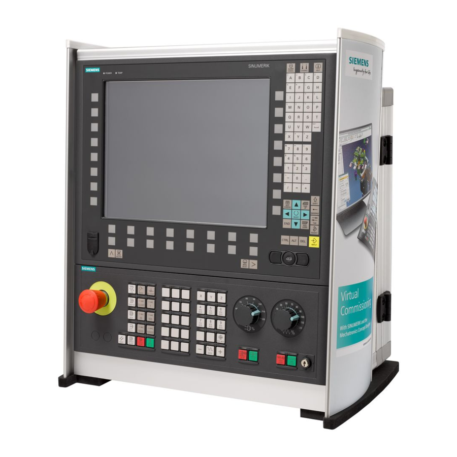
The SINUMERIK 840DE sl is available as an export version for use in countries where approval is required. System configuration The heart of the SINUMERIK 840D sl is the Numerical Control Unit (NCU). It combines NCK, HMI, PLC, closed-loop control and communication tasks. Components For operating, programming, and visualization, the corresponding HMI software is integrated in the NCU software. - Page 12 Up to 4 distributed operator panel fronts can be operated on an NCU or PCU 50.3. Figure 1-1 Typical topology of the SINUMERIK 840D sl complete system The following components can be attached to the Control Unit: ● SINUMERIK operator panel front with TCU/PCU 50.3 and machine control panel/pushbutton panel ●...
-
Page 13: Variants
● Use of an NCU 730 is recommended for maximum dynamics and accuracy in mold making or in the high speed cutting sector. ● The NCU 730.2 PN is the new flagship of the SINUMERIK 840D sl and, with a significantly higher PLC capacity than an NCU 730.2, represents the most advanced configuration within the SINUMERIK 840D sl range. - Page 14 System overview 1.3 Variants Table 1-1 Variants Property NCU 710.1/.2 NCU 720.1/.2/.2 PN NCU 730.1/.2/.2 PN DRIVE CLiQ ports Axes Up to 6 Up to 31 Up to 31 NX10/15 Up to 2 Up to 5 Up to 5 Manual, 07/2007, 6FC5397-0AP10-2BA0...
-
Page 15: Application Planning
Application Planning Secondary electrical conditions 2.1.1 Connection Conditions Compliance with the connection conditions The controller is tested for compliance with the ambient conditions specified below. Fault- free operation is only ensured if: ● These ambient conditions are maintained when storing, transporting and operating the equipment. - Page 16 If necessary, these interfaces can be isolated safely using a supplementary adapter (insulation voltage 230 V AC). Although these adapters are not included in the Siemens scope of delivery, you can buy these parts from your local dealer, who will be happy to advise you.
-
Page 17: Grounding Concept
2.1.3 Grounding concept Components The SINUMERIK 840D sl system consists of a number of individual components which have been designed so that the system complies with the appropriate EMC and safety standards. The individual system components are: ● Numerical Control Unit (NCU): ●... - Page 18 Application Planning 2.1 Secondary electrical conditions It is permissible to have a cluster of operator components for ground connection/PA. Example: The Control Unit on the swivel arm. It is sufficient in this instance to connect the ground connections of, for example, the PCU, TCU and operator panel front using a cable and to route a shared grounding conductor to the central ground connection in the control cabinet.
-
Page 19: Ri Suppression Measures
However, if the system cannot operate without them, then the cable shields must be connected at both ends. Furthermore, the non-Siemens device must be connected to the controller via an equipotential bonding cable. -
Page 20: Ambient Climatic And Mechanical Conditions
Application Planning 2.2 Ambient Climatic and Mechanical Conditions Rules for routing cables In order to maximize noise immunity for the complete system (controller, power section, machine) the following EMC measures must be observed: ● The distance between signal lines and load cables must be maximized. ●... -
Page 21: Transport And Storage Conditions
Application Planning 2.2 Ambient Climatic and Mechanical Conditions Requirements standards Long-term storage EN 60721-3-1 Shipping EN 60721-3-2 Stationary operation EN 60721-3-3 2.2.2 Transport and Storage Conditions Components in original packaging The following specifications apply to components in transport packaging: Table 2-1 Climatic environmental conditions according to EN 60721-3-1/-3-2, Class 1K3/2K4 Transport Storage... -
Page 22: Operating Conditions
Application Planning 2.2 Ambient Climatic and Mechanical Conditions DANGER Incorrect handling of backup batteries can lead to a risk of ignition, explosion and combustion. The stipulations of DIN EN 60086-4, in particular regarding avoidance of mechanical or electrical tampering of any kind, must be complied with. 2.2.3 Operating Conditions Climatic ambient conditions... - Page 23 Please contact your sales representative for assistance and support. If compliance with limit value class B (residential areas) is required, please contact your local Siemens office or representative. NOTICE Please see the relevant SINAMICS documentation for EMC notes on how to deal with line filters and reactors.
- Page 24 Application Planning 2.2 Ambient Climatic and Mechanical Conditions Manual, 07/2007, 6FC5397-0AP10-2BA0...
-
Page 25: Safety Information
Safety Information Danger notices The following notices are intended firstly for your personal safety and secondly to prevent damage occurring to the product described or any connected devices and machines. Non- observance of the warnings can result in severe personal injury or property damage. DANGER Only appropriately qualified personnel may commission/start-up SINUMERIK equipment. - Page 26 Repairs to devices that have been supplied by our company may only be carried out by SIEMENS customer service or by repair centers authorized by SIEMENS. When replacing parts or components, only use those parts that are included in the spare parts list.
-
Page 27: Esd Notices
Safety Information 3.2 ESD notices ESD notices CAUTION The modules contain electrostatically sensitive devices. Discharge yourself of electrostatic energy before touching the components. The easiest way to do this is to touch a conductive, grounded object immediately beforehand (for example, bare metal parts of control cabinet or the protective ground contact of a socket outlet). - Page 28 Safety Information 3.2 ESD notices Manual, 07/2007, 6FC5397-0AP10-2BA0...
-
Page 29: Description
Description Features A Control Unit contains the following interfaces and modules: ● Battery-backed SRAM for persistent data storage ● Battery-backed real-time clock ● PROFIBUS interfaces ● Ethernet ports ● PROFINET interfaces for NCU 720.2 PN and NCU 730.2 PN ● Slot for a CompactFlash Card ●... - Page 30 Description 4.2 Illustration Figure 4-1 Representation of the NCU 720.1/730.1/730.2 Control Units with PROFINET The following figure shows an NCU 720.2 PN/730.2 PN with its interfaces and control and display elements (fault LEDs and status indicators). CAUTION The PROFINET interfaces of the integrated PLC 319-3 PN/DP are permanently assigned to the option slot on the "PN NCUs".
- Page 31 Description 4.2 Illustration Figure 4-2 Representation of the NCU 720.2 PN/730.2 PN Manual, 07/2007, 6FC5397-0AP10-2BA0...
-
Page 32: Type Plate
Description 4.3 Type plate Type plate Side-mounted type plate The following figure shows you all the information included on the type plate located on the side of the unit. Figure 4-3 Type plate You might need to access the information provided on the side-mounted type plate after the equipment has been mounted. -
Page 33: Power Supply
Description 4.4 Power supply Power supply External 24 V power supply Power is supplied to the Control Unit by an external 24 V power supply (e.g., SITOP). The following power consumption values for the Control Units provide a configuration basis for calculating the 24 V DC power supply. - Page 34 Description 4.4 Power supply Table 4-2 Requirements of the DC supply Rated voltage According to EN 61131-2 24 V DC Voltage range (average value) 20.4 to 28.8 V DC Voltage ripple peak-to-peak 5 % (unfiltered 6-pulse rectification) Ramp-up time at power-on Non-periodic overvoltages ≤...
-
Page 35: Operating And Display Elements
Operating and display elements Overview of operating and display elements NCU 710.1/720.1/720.2 PN/730.1/730.2/730.2 PN Figure 5-1 Position of operator control and display elements Manual, 07/2007, 6FC5397-0AP10-2BA0... - Page 36 Operating and display elements 5.1 Overview of operating and display elements NCU 710.2/720.2 Figure 5-2 Position of operator control and display elements Manual, 07/2007, 6FC5397-0AP10-2BA0...
-
Page 37: Compactflash Card
Operating and display elements 5.2 CompactFlash Card CompactFlash Card 5.2.1 Properties Application The CompactFlash Card is delivered bootable. It is not supplied with the control unit and must be ordered as a separate component. The CompactFlash Card is inserted in the CF plug-in slot (X109 interface). CAUTION The CompactFlash Card may only be inserted or removed when the control unit is disconnected from the power supply. -
Page 38: Inserting The Compactflash Card
Operating and display elements 5.2 CompactFlash Card 5.2.2 Inserting the CompactFlash card Proceed as follows NOTICE ESD: you must discharge yourself at the cabinet or ground terminal before touching the CompactFlash Card. Please proceed as follows: 1. Switch off the power supply. 2. -
Page 39: Led Displays
Operating and display elements 5.3 LED displays LED displays Table 5-1 Meaning of LED states Name Function Status Meaning Ready There is at least one fault (e.g. RESET, watchdog monitoring etc. ) or the Control Unit is booting up. Flashing red/yellow Error accessing CompactFlash Card (0.5 Hz) Yellow... -
Page 40: Reset Button
Operating and display elements 5.4 Reset button Reset button Performing a reset operation The RESET button is located behind the blanking plate. A reset operation resets the entire system and requires a system restart. This is comparable to a "Power On reset" except that the 24 V power supply does not have to be switched off. 7-segment display Displaying messages The 7-segment display is located behind the blanking plate of the Control Unit. -
Page 41: Start-Up And Mode Selector Switch
Operating and display elements 5.6 Start-up and mode selector switch Start-up and mode selector switch Layout The Control Unit has two coding switches in the lower section of the front panel. ● The left switch (labeled SIM/NCK) is the NCK startup switch. Setting during normal operation: "0"... - Page 42 Operating and display elements 5.6 Start-up and mode selector switch Manual, 07/2007, 6FC5397-0AP10-2BA0...
-
Page 43: Interfaces
Interfaces Interface overview Interface overview Table 6-1 Overview of available external interfaces Interface Designation Plug-connector type DRIVE-CLiQ (0) X100 Spec. RJ45 socket DRIVE-CLiQ (1) X101 Spec. RJ45 socket DRIVE-CLiQ (2) X102 Spec. RJ45 socket DRIVE-CLiQ (3) X103 Spec. RJ45 socket DRIVE-CLiQ (4) X104 (only NCU 720/730) Spec. -
Page 44: Drive Cliq Interfaces X100 - X105
Interfaces 6.2 DRIVE CLiQ Interfaces X100 - X105 DRIVE CLiQ Interfaces X100 - X105 Properties ● Automatic detection of components ● 24 V / 450 mA per DRIVE-CLiQ interface is provided for the connection of encoders and measuring systems Features Table 6-2 X100 - X103 or X100 –... -
Page 45: Profibus Dp Interfaces X126 And X136
Interfaces 6.3 PROFIBUS DP interfaces X126 and X136 Position of plug connectors Figure 6-1 DRIVE-CLiQ interface PROFIBUS DP interfaces X126 and X136 6.3.1 Properties Properties ● Isolated RS 485 interface ● Max. data rate 12 Mbaud ● Supports master/slave operation ●... -
Page 46: Application
Interfaces 6.3 PROFIBUS DP interfaces X126 and X136 Interface assignment for X126, X136 Table 6-5 PROFIBUS DP interfaces (X126, X136) Signal name Signal type Meaning Ground to P24_SERV 2RS_DP RS485 differential signal 2RTS_DP Request to Send Ground to 1P5 5 V power supply for bus terminal, external, short circuit-proof P24_SERV 24 V for teleservice, short circuit-proof, 150 mA maximum 2XRS_DP... -
Page 47: Ethernet Interfaces (X120, X130, X127)
Interfaces 6.4 Ethernet interfaces (X120, X130, X127) Note A teleservice adapter can only be connected to one of the two interfaces. Ethernet interfaces (X120, X130, X127) 6.4.1 Features Properties The interfaces are full-duplex 10/100 Mbit Ethernet ports. Both ports are connected as an Ethernet terminal. - Page 48 Interfaces 6.4 Ethernet interfaces (X120, X130, X127) Pin assignment Table 6-8 Ethernet interfaces (X120, X130, X127) Signal name Signal type Meaning Output Transmit data + Output Transmit data - Input Receive data + Input Receive data - Position of connectors The following figure shows the mounting position and designation of the Ethernet connectors on the module.
-
Page 49: Application
Interfaces 6.4 Ethernet interfaces (X120, X130, X127) MAC addresses A type plate for the MAC addresses of the Ethernet interfaces is attached to the front panel of the Control Unit: Figure 6-4 MAC addresses of Ethernet interfaces X120, X130, X127 You can see this type plate when you open the front cover of the Control Units without PROFINET. -
Page 50: Profinet Interfaces Port 1 - Port 4
Interfaces 6.5 PROFINET interfaces port 1 - port 4 PROFINET interfaces port 1 - port 4 6.5.1 Properties Properties The interfaces are full-duplex 100 Mbit Ethernet ports with an integrated 4-port switch and a TCP/IP address for the 4 ports. Figure 6-5 Representation of the PROFINET interfaces Interface features... - Page 51 Interfaces 6.5 PROFINET interfaces port 1 - port 4 Pin assignment Table 6-10 PROFINET interfaces port 1, 2, 3, 4 Signal name Signal type Meaning Output Transmit data + Output Transmit data - Input Receive data + Input Receive data - Position of the ports The 4 ports for the PROFINET connection are in the option slot of NCU 720.2 PN and NCU 730.2 PN.
-
Page 52: Application
Interfaces 6.5 PROFINET interfaces port 1 - port 4 MAC addresses A type plate for with the MAC addresses of the PROFINET/Ethernet interfaces is attached to the front panel of the NCU 720.2 PN and NCU 730.2 PN: Figure 6-6 MAC addresses of the PROFINET/Ethernet interfaces You can see this type plate when you open the front cover of the NCU 720.2 PN and NCU 730.2 PN. -
Page 53: Digital Inputs/Outputs X122 And X132
Interfaces 6.6 Digital inputs/outputs X122 and X132 Digital inputs/outputs X122 and X132 6.6.1 Properties Interface features Table 6-12 Interfaces X122 and X132 Features Version Plug-connector type Micro Combicon Connection option up to 0.25 mm Current carrying capacity 4 A, maximum Position of plug connectors X122 X132... - Page 54 Interfaces 6.6 Digital inputs/outputs X122 and X132 Wiring diagram and block diagram The following figure shows the wiring diagram based on an example of the NCU 710 and the block diagram of the digital inputs and outputs. Figure 6-8 Wiring diagram and block diagram of the digital inputs/outputs Manual, 07/2007, 6FC5397-0AP10-2BA0...
-
Page 55: Assignment
Interfaces 6.6 Digital inputs/outputs X122 and X132 6.6.2 Assignment Interface assignment of X122 and X132 Table 6-13 X122 digital inputs/outputs Signal name Signal type Meaning Digital input 0 Digital input 0 Digital input 0 Digital input 0 Ground for DI0 - DI3 (functionally-separated relative to M) Ground DI/DO8 Digital input/output 8... -
Page 56: Technical Data
Interfaces 6.6 Digital inputs/outputs X122 and X132 6.6.3 Technical data Digital inputs on X122/X132 Table 6-15 Technical data of digital inputs X122/X132 Parameter Values Voltage -3 V to 30 V Typical power consumption 10 mA at 24 V DC Galvanic isolation Reference potential is terminal M1 or M2 Signal level (including ripple) High signal level: 15 V to 30 V... -
Page 57: Application
Interfaces 6.7 Power supply X124 6.6.4 Application Connecting sensors and actuators Digital inputs and outputs can be used to connect various sensors and actuators to the two 12-pin connectors (X122 and X132) on the front panel. The following types of digital I/O are used: ●... - Page 58 Interfaces 6.7 Power supply X124 Note The 24 V is looped through via the 24 V connector. In this case, pin 1 is jumpered with pin 2, and pin 3 is jumpered with pin 4. Position of power supply interface Figure 6-9 Power supply interface Application of X124...
-
Page 59: Test Sockets X131 - X134
Interfaces 6.8 Test sockets X131 - X134 Test sockets X131 - X134 Application The test sockets are used to output analog signals. Any interconnectable signal can be output to any test socket on the control unit. ● Max. output range of the test signal: 0 to 5 V ●... -
Page 60: Usb Interfaces X125, X135
Interfaces 6.9 USB interfaces X125, X135 USB interfaces X125, X135 The USB interfaces are used exclusively for service purposes, correspond to the norm and are, therefore, not described in detail here. Table 6-19 Interfaces X125 and X135 Features Versions Plug-connector type: Double USB socket –... -
Page 61: Dimension Drawings
Dimension drawings Dimension drawing Figure 7-1 Dimension drawing of control unit Manual, 07/2007, 6FC5397-0AP10-2BA0... - Page 62 Dimension drawings 7.1 Dimension drawing Manual, 07/2007, 6FC5397-0AP10-2BA0...
-
Page 63: Mounting
Mounting Safety information Open equipment These modules are open equipment. This means they may only be installed in housings, cabinets or in electrical service rooms that can be entered or accessed exclusively by means of a key or tool. Housings, cabinets, or electrical equipment rooms may only be accessed by trained or authorized personnel. -
Page 64: Installation Types
Mounting 8.2 Installation types Installation types Prerequisite The Control Unit is installed in a control cabinet along with the SINAMICS components. The following prerequisites must be met to install a Control Unit: ● The control cabinet has been installed and wired. ●... - Page 65 Mounting 8.2 Installation types Figure 8-1 Mounting aids Spacers for mounting on the rear wall of the control cabinet Lugs for mounting directly on the rear wall of the control cabinet (external heat dissipation) Cutouts for lateral mounting on SINAMICS drive group Mounting instructions A seal can be provided for segregated heat removal on the Control Unit (apart from NCU 710.2 and NCU 720.2).
-
Page 66: Mounting The Control Unit On The Rear Wall Of The Control Cabinet
Mounting 8.3 Mounting the control unit on the rear wall of the control cabinet Mounting the control unit on the rear wall of the control cabinet 8.3.1 Mounting control unit using spacers Introduction Spacers can be used to mount the control unit on a bare-metal highly-conductive rear wall of a control cabinet. - Page 67 Mounting 8.3 Mounting the control unit on the rear wall of the control cabinet Figure 8-2 Mounting the Control Unit without spacers Manual, 07/2007, 6FC5397-0AP10-2BA0...
-
Page 68: Mounting The Control Unit For Segregated Heat Removal
Mounting 8.3 Mounting the control unit on the rear wall of the control cabinet 8.3.3 Mounting the Control Unit for segregated heat removal Introduction If you wish to perform segregated heat removal on the NCUs with cooling fins, the NCUs can be mounted directly on the rear wall of the control cabinet without spacers. - Page 69 Mounting 8.3 Mounting the control unit on the rear wall of the control cabinet Proceed as follows 1. Remove the spacers. 2. Fit the seal around the cooling ribs of the Control Unit. 3. Loosen the three M3 screws (0.8 Nm) on the upper clip and push the clip up until the upper hole protrudes beyond the housing.
-
Page 70: Lateral Mounting Of Control Unit On The Sinamics Drive Line-Up
Mounting 8.4 Lateral mounting of Control Unit on the SINAMICS drive line-up Lateral mounting of Control Unit on the SINAMICS drive line-up Introduction The Control Unit can also be mounted laterally on the SINAMICS drive line-up, on the side panel of a SINAMIC S120 Line Module. The required mounting elements are supplied with the Line Module. -
Page 71: Connections
The following overview shows an example of the various interfaces and their connection options. Note All devices in the SINUMERIK 840D sl and SINAMICS S120 product families appear in Catalog NC 61. SIMATIC products that can be connected to the Control Unit appear in Catalog PM 10. - Page 72 Connections 9.1 Overview Figure 9-1 Connection options for a Control Unit Manual, 07/2007, 6FC5397-0AP10-2BA0...
-
Page 73: Safety Information For Wiring
Connections 9.2 Safety information for wiring Safety information for wiring Note the following: Safety information DANGER The system power supply must be disconnected when you wire the control unit. NOTICE If your axis grouping contains a Smart Line Module without DRIVE-CliQ (5 kW or 10 kW), you must assign the Smart Line Module enable signal to digital output X122.1 on the control unit. -
Page 74: Power Supply
Connections 9.4 Power supply Figure 9-2 Removing the front cover Note All cables must be routed vertically upwards to the fullest extent possible so that the front cover can be closed. The front cover is open and in the up position. Power supply 9.4.1 Safety regulations... -
Page 75: Standards And Regulations
Connections 9.4 Power supply Rules for safe operation In order to ensure the safe operation of your equipment, implement the following measures, adapting them to suit your conditions: ● An EMERGENCY OFF concept in accordance with the generally accepted rules of current engineering practice (e.g., European Standards EN 60204, EN 418 and similar). -
Page 76: Mains Voltage
Connections 9.4 Power supply 9.4.3 Mains voltage Rules for the line voltage The following list indicates what you must take into account for the line voltage: ● For stationary installations or systems that do not have all-pole line disconnect switches, the building installation must include a line disconnect switch or a fuse. -
Page 77: Connecting The Power Supply
Connections 9.5 DRIVE CLiQ components 9.4.4 Connecting the power supply Wiring the screw-type terminal block The required 24 V DC load power supply is wired to the screw-type terminal block (X124). DANGER The 24 V DC should be configured as functional extra-low voltage with safe isolation. Supply system lines Use flexible cables with a cross section of 0.25 to 2.5 mm (or AWG 23 to AWG 13) for wiring... - Page 78 Connections 9.5 DRIVE CLiQ components Rules for DRIVE-CLiQ sockets The following rules must be observed when using DRIVE-CLiQ sockets: ● The control unit must be connected to X200 on the first booksize power unit after it. ● The DRIVE-CLiQ lines between each of the power units should be connected from interface X201 to X200 on the next component.
-
Page 79: Connectable Drive-Cliq Components
Connections 9.5 DRIVE CLiQ components 9.5.2 Connectable DRIVE-CLiQ components Components As a rule, all SINAMICS components approved for SINUMERIK can be connected using the DRIVE-CLiQ interface. Table 9-2 Components with DRIVE-CLiQ Component Description Active/Smart Line Module, Line Modules provide the central power supply to the DC link. Booksize Single/Double Motor Motor Modules draw their power from the DC link to supply the... -
Page 80: Digital I/Os
Connections 9.6 Digital I/Os Digital I/Os 9.6.1 Connecting cables for digital inputs/outputs The following conditions apply to connecting cables: ● Flexible cable, cross section 0.25 mm ● Ferrules are not required. ● You can use ferrules without an insulating collar in accordance with DIN 46228, Form A long version. -
Page 81: Using A Shield Connection
Connections 9.6 Digital I/Os Using shielded cables If a shielded cable is used, the following additional actions are required: 1. Attach the cable shield to a grounded shielding bus immediately after the cable entry point in the cabinet (strip the insulation off the cable for this purpose). 2. -
Page 82: Profibus / Mpi
Connections 9.7 PROFIBUS / MPI PROFIBUS / MPI 9.7.1 Connection components in PROFIBUS Connection components Individual nodes are connected by means of bus connectors and PROFIBUS cables. Remember to provide a bus connector with a programming port at either end of the subnet. This will give you the option of expanding the subnet if required, for example, for a programming device. -
Page 83: Profibus Cable Lengths
Connections 9.7 PROFIBUS / MPI Cable features Table 9-3 Properties of PROFIBUS cables Features Values Wave impedance Approx. 135 to 160 Ω (f = 3 to 20 MHz) Loop resistance ≤115 Ω/km Effective capacitance 30 nF/km Damping 0.9 dB/100 m (f = 200 kHz) Permissible conductor cross section 0.3 mm to 0.5 mm... -
Page 84: Rules For Routing Profibus Cables
Connections 9.7 PROFIBUS / MPI 9.7.4 Rules for routing PROFIBUS cables Routing bus cables When routing the PROFIBUS cable, you must avoid: ● twisting ● stretching and ● squeezing Supplementary conditions In addition, when routing a bus cable for indoor use, you must take into account the following boundary conditions (dA = external cable diameter): Table 9-5 Boundary conditions for routing of PROFIBUS cables... -
Page 85: Disconnecting Stations From The Profibus
Connections 9.7 PROFIBUS / MPI Wiring the bus connector 1. Proceed as follows to connect the bus connector: 2. Plug the bus connector into the corresponding interface on the control unit. 3. Screw the bus connector into place. As the control unit is located at the start or end of a segment, you must switch on the terminating resistor ("ON"... -
Page 86: Operating The X136 Interface As Mpi
9.8.1 Wiring PROFINET Prerequisite For SINUMERIK 840D sl, a PROFINET system can only be installed with the following Control Units: NCU 720.2 PN, NCU 730.2 PN Data Transmission Rate and Cables For PROFINET, you require a data transmission rate of 100 Mbit/s (Fast Ethernet) full duplex. -
Page 87: Profinet Cables
Connections 9.8 PROFINET 9.8.2 PROFINET cables Cable and connector types Note For connecting PROFINET to the NCU we recommend using a connector with a 145° cable outlet (IE FC RJ45 plug 145). Figure 9-6 RJ45 PN connector with a 145° cable outlet Table 9-6 Connector types for PROFINET Connector... -
Page 88: Preparing The Twisted Pair Cables
Connections 9.8 PROFINET 9.8.3 Preparing the twisted pair cables Function The IE FC RJ45 Plugs are used to install uncrossed 100 Mbit/s Ethernet connections up to 100 m without the use of patches. Crossed cables can also be installed by swapping the transmit and receive pair in a plug. - Page 89 Connections 9.8 PROFINET ③ ④ ⑤ Lower the contact cover so that Use a screwdriver to turn the Close the case cover and press the strands are contacted. snap ring 90°. This will ensure down until it connects with the tension and cable grip.
-
Page 90: Example Profinet Cba Configuration
Connections 9.8 PROFINET 9.8.4 Example PROFINET CBA configuration The following figure shows a typical system configuration with PROFINET CBA. Figure 9-7 Example PROFINET CBA configuration Station name Module type Interface IP address Central NCU 730.2 PN X120 192.168.200.1 Port 1 192.168.200.2 PCU 50.3 X500... -
Page 91: Technical Data
Technical Data Table 10-1 General technical data Safety Protection class I (protective conductor) as per EN 61800-5-1 Degree of protection to EN 60529 IP20 or IPXXB Certifications CE, cULus Pollution degree Cooling Open-circuit-ventilated Mounting position Vertical Mechanical environmental conditions Transportation (in transportation 2M3 according to EN 60721-3-2 packaging) Storage... - Page 92 Technical Data Table 10-3 Electrical and mechanical data (2) NCU 720.2 PN NCU 730.1/.2 NCU 730.2 PN Main memory 512 MB DRAM 512 MB DRAM 512 MB DRAM 1 MB SRAM 1 MB SRAM 1 MB SRAM SIMATIC S7 - integrated PLC 319-3 PN/DP PLC 317-2 DP PLC 319-3 PN/DP...
-
Page 93: Spare Parts/Accessories
Spare Parts/Accessories 11.1 Dual fan/ battery module 11.1.1 Application Functions of the dual fan/battery module The dual fan/battery module can perform the following tasks: ● Cooling the CPU by means of two redundant fans. ● SRAM buffering if the SuperCap is insufficient. The Control Unit monitors the temperature inside the module and the functioning of the fan. -
Page 94: Mounting
Spare Parts/Accessories 11.1 Dual fan/ battery module NOTICE The Control Unit cannot be operated without fans, i.e. the Control Unit will not power up if the dual fan/battery module is not functioning. Battery A 3 V lithium battery can be inserted in the dual fan/battery module. The battery is preassembled with an approximately 4 cm long cable with plug connector. - Page 95 Spare Parts/Accessories 11.1 Dual fan/ battery module Proceed as follows Proceed as follows to replace the dual fan/battery module but only observe points 3 and 4 if you want to replace the battery as well: 1. Gently press the dual fan/battery module backwards. This detaches the module from its front interlock.
-
Page 96: Tm15 Terminal Module
Spare Parts/Accessories 11.2 TM15 Terminal Module 11.2 TM15 Terminal Module Properties The TM15 Terminal Module can be used to implement measuring probe inputs and cam outputs. In addition, the Terminal Module provides drive-related digital inputs and outputs with short signal delay times. TM15 is connected by means of DRIVE-CLiQ. Each of the 24 isolated DI/O can be parameterized channel-by-channel as a digital input (DI), digital output (DO), measuring input, or output of the output cam. -
Page 97: Description
Properties Using this module, you can expand the performance of an axis grouping of the SINUMERIK 840D sl CNC automation system. Each NX10 can control up to 3 additional axes and each NX15 can control up to 6 additional axes. - Page 98 Spare Parts/Accessories 11.4 NX10/15 Display Figure 11-3 Representation of NX10/15 (without cover) Type plate The NX10/15 module type plate contains basically the same information as the control unit type plate (see Section 4.4). Manual, 07/2007, 6FC5397-0AP10-2BA0...
-
Page 99: Operating And Display Elements
Spare Parts/Accessories 11.4 NX10/15 11.4.2 Operating and display elements LED displays Table 11-1 Description of LEDs on the NX10/15 Color Status Description Electronic power supply outside permissible tolerance range Steady-light signal NX10/15 is ready for operation RDY, Green Blinklight 2 Hz Writing to CompactFlash Card READY Steady-light signal... -
Page 100: Interfaces
Spare Parts/Accessories 11.4 NX10/15 11.4.3 Interfaces Connection example Figure 11-4 NX10/15 sample connection Note The digital inputs/outputs are reserved by the system (terminal assignment). Manual, 07/2007, 6FC5397-0AP10-2BA0... - Page 101 Spare Parts/Accessories 11.4 NX10/15 DRIVE-CLiQ interfaces X100 - X103 Table 11-2 DRIVE-CLiQ interface (X100 - X103) Signal name Technical specifications Transmit data + Transmit data - Receive data + Reserved, do not use Reserved, do not use Receive data - Reserved, do not use Reserved, do not use + (24 V)
- Page 102 Spare Parts/Accessories 11.4 NX10/15 Note An open input is interpreted as "low". The "rapid inputs" can be used for positioning measurement. To enable digital inputs (DI) 0 to 3 to function, terminal M1 must be connected. This can be done as follows: Connect the coupled-motion reference ground of the digital inputs, or provide a jumper to terminal M.
-
Page 103: Dimension Drawing
Spare Parts/Accessories 11.4 NX10/15 11.4.4 Dimension drawing Figure 11-5 NX10/15 dimension drawing Manual, 07/2007, 6FC5397-0AP10-2BA0... -
Page 104: Mounting
Spare Parts/Accessories 11.4 NX10/15 11.4.5 Mounting Mounting aids Figure 11-6 NX10/15 mounting aids Designs Basically, the NX10/15 is integrated into the SINAMICS drive line-up in exactly the same way as the Control Unit (see Chapter 8, Mounting). ● Lateral mounting of NX 10/15 on the SINAMICS drive line-up ●... - Page 105 Spare Parts/Accessories 11.4 NX10/15 CAUTION The 80 mm ventilation spaces above and below the components must be observed. Mounting an NX10/15 on another NX10/15 Table 11-5 Mounting an NX10/15 on another NX10/15 Opening the cover. Unscrewing the screw. The bracket must be moved so that the pin is in the opening of the bracket.
-
Page 106: Port
Spare Parts/Accessories 11.4 NX10/15 Mounted bracket. Closing the cover. 11.4.6 Port NX10/15 DRIVE-CLiQ topology NX10/15 components can be connected to the control unit via DRIVE-CLiQ. The following rules apply to wiring of the NX10/15: ● Only one star topology is permitted between the NX10/15 and the control unit. This means that only one NX10/15 can be operated per DRIVE-CLiQ port on a control unit. -
Page 107: Technical Data
Spare Parts/Accessories 11.4 NX10/15 The following figure shows a sample topology: Figure 11-7 NX10/15 topology 11.4.7 Technical Data Table 11-7 Technical data Parameters Values Input voltage 24 V DC (20.4 – 28.8) Current (without DRIVE-CLiQ or digital outputs) 0.8 A PE/ground connection On housing with M5/3 Nm screw Dimensions (WxHxD) -
Page 108: Ordering Data
Spare Parts/Accessories 11.5 Ordering data 11.5 Ordering data Table 11-8 Ordering data for spare parts Spare parts Order numbers NCU 710.1 with PLC 317-2DP 6FC5371-0AA10-0AA0 NCU 710.2 with PLC 317-2DP 6FC5371-0AA10-0AA1 NCU 720.1 with PLC 317-2DP 6FC5372-0AA00-0AA0 NCU 720.2 with PLC 317-2DP 6FC5372-0AA00-0AA1 NCU 720.2 PN with PLC 319-3PN/DP 6FC5372-0AA01-0AA1... -
Page 109: Appendix
Appendix Abbreviations American Wire Gauge BERO Proximity limit switch B-MPI Handheld unit with MPI connection CAT5 Quality class (category) for shielded twisted pair network cables. Class 5 states that these cables have a particularly low damping factor, making them suitable for 100 Mbit/s-FastEthernet networks. Component Based Automation: Component Based Automation Computerized Numerical Control Computerized numerical control Central Processing Unit Central processing unit... -
Page 110: Publication-Specific Information
This document will be continuously improved with regard to its quality and ease of use. Please help us with this task by sending your comments and suggestions for improvement via e-mail or fax to: E-mail: mailto:docu.motioncontrol@siemens.com Fax: +49 (0) 9131/98 - 63315 Please use the fax form on the back of this page. - Page 111 Appendix A.2 Publication-specific information Manual, 07/2007, 6FC5397-0AP10-2BA0...
-
Page 112: Overview
Appendix A.2 Publication-specific information A.2.2 Overview Manual, 07/2007, 6FC5397-0AP10-2BA0... -
Page 113: Index
Index Digital I/O interface Assignment, 55 Technical data, 56 Digital inputs/outputs Active Line Module, 79 Wiring diagram, 54 Actuators, 71 DRIVE-CLiQ Air-conditioning Assignment, 44 Storage and transport, 21, 22 Connectable components, 79 Test standards, 20 Rules for wiring, 77 Ambient conditions, 15 DRIVE-CLiQ interface Axes, 13 Assignment, 44... - Page 114 Index Interface PLC mode selector switch, 41 Digital I/O, 53 Power supply, 33 DRIVE-CLiQ, 44 Connection, 77 Ethernet, 47 Rules for the line voltage, 76 Power supply, 57 Safety rules, 75 PROFIBUS, 45 VDE guideline, 75 PROFINET, 50 Power supply interface Interfaces, 29 Assignment, 57 PROFIBUS cable...
- Page 115 Index Subnet Connection components, 82 Ventilation, 93 Segment, 82 Vibratory load, 20 Terminating resistor, 82 X122/X132 interfaces, 80 Terminating resistor, 82 Test and diagnostic messages, 40 Test sockets, 59 TM15 Terminal Module, 96 Twisted pair cable, 88 Type plate, 32 Manual, 07/2007, 6FC5397-0AP10-2BA0...
- Page 116 Index Manual, 07/2007, 6FC5397-0AP10-2BA0...
Need help?
Do you have a question about the SINUMERIK 840D sl and is the answer not in the manual?
Questions and answers