Table of Contents
Advertisement
Quick Links
Advertisement
Table of Contents
Troubleshooting

Related Manuals for Splicecom Maximiser


Summary of Contents for Splicecom Maximiser
- Page 1 Installation & Reference Manual Version 3.2 April 2010...
- Page 2 Installation and Reference Manual Document No. 001 Version No. V3.2/0410/6 © Copyright SpliceCom Ltd SpliceCom Ltd The Hall Business Centre, Berry Lane Chorleywood, Herts WD3 5EX Tel: 01923 287700 Website: www.splicecom.com...
-
Page 3: Table Of Contents
Contents Introduction ................................. 1 Platform Overview .............................. 2 5 Series Hardware ............................2 4 Series Hardware ............................4 maximiser Handsets ............................6 maximiser Software ............................11 System Architecture ............................15 Installing a System............................. 21 System Operation ............................. 24 Manager ................................ 24 Configuring System Details .......................... - Page 4 Installation and Reference Manual Leaving a Message ............................. 192 Accessing Voicemail ........................... 193 Remote Access to Voicemail ........................202 Setting up Voicemail Email ......................... 207 Setting up SMS Alerts ..........................209 Using voicemail with a Paging Port ......................209 Voicemail for a Department ........................209 Creating an Auto Attendant ........................
- Page 5 Installation and Reference Manual Unassigned Phones ........................... 319 Unassigned Modules ..........................319 System ................................. 319 Licences ..............................320 Administrators ............................. 320 Utilities ................................ 321 Area Codes ..............................322 WAN Links ..............................322 Technical Data ..............................326 Cable Specifications ........................... 328 Relay Outputs .............................
-
Page 7: Introduction
The purpose of this manual is to give a step by step guide on how to install, configure and troubleshoot a maximiser system. The manual starts with a feature guide of each element of a system together with an understanding of the architecture used and finishes with a complete listing of each configuration field and its function together with in-depth technical data. -
Page 8: Platform Overview
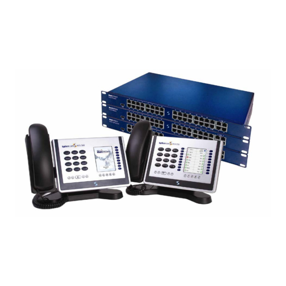
4 to 10,000 extensions. It is a purely IP system supporting either traditional analogue or IP Phones. 5 Series Hardware The 5 series maximiser range consists of the 5100 Call Server, 5300 Phone and 5108 Call Server. Each module is 1u in height and can be mounted in a 19” rack. 5100 Call Server The main control unit of the system, this module provides: •... - Page 9 Installation and Reference Manual 5300 Phone This module provides connection for standard analogue telephones: Available as 5315 providing 15 POTS ports or 5330 • providing 30 POTS ports Support for DTMF analogue handsets, PCS 5/10, fax • machines and modems Caller Display support •...
-
Page 10: Series Hardware
Installation and Reference Manual 4 Series Hardware The 4 series maximiser system is made up of 3 components – 4100 Call Server, 4200 Trunk and 4300 Phone. The 4140 Remote Call Server combines the functionality of all three of these modules in a single unit. - Page 11 Installation and Reference Manual 4300 Phone This module provides connection for standard analogue telephones: Available as 4315 providing 15 POTS ports or 4330 • providing 30 POTS ports Support for DTMF analogue handsets, PCS 5/10, fax • machines and modems Caller Display support •...
-
Page 12: Maximiser Handsets
Installation and Reference Manual 4400 Voice Compression Module As an alternative to the 64kbps, G.711 voice supported as standard on maximiser, 8kbps, G.729a based encoding, provides an excellent balance between voice quality and bandwidth efficiency. The 4400 Voice Compression Module provides 16 channels, of 8 kbps, G.729a based compression and can be deployed to provide a higher density of calls between 4100 Call Servers/4140 Remote Call Servers over low speed WAN links. - Page 13 Installation and Reference Manual PCS 570 This IP phone provides: Standard 12 button telephony functionality • Full colour, backlit, graphics display (240 x 320) with auto- • dimming, context sensitive Wide-angle tilting keypad/display panel • 18 intuitive, multi-functional context sensitive keys •...
- Page 14 Installation and Reference Manual PCS 410 This IP Phone provides: Standard telephony functionality • Graphical touch screen LCD interface • Context Sensitive Screen • Ability to display real time video and graphical information • during call Power over Ethernet support – can be powered via a LAN •...
- Page 15 Installation and Reference Manual PCS 100 The PCS 100 is an IP Phone presented as a conventional business telephone. It provides caller ID, a dedicated Busy Lamp Field together with pre programmed buttons for simple and easy access to system features.
- Page 16 Installation and Reference Manual PCS 10 The PCS 10 is an analogue handset providing the following features: Standard 12 button telephone keypad • 3 line LCD display with contrast settings • Display of Calling Line Number/Name & Called Line Name •...
-
Page 17: Maximiser Software
• Voice Compression Card maximiser supports G.711 encoding with echo suppression as standard for transporting voice. Where compressed voice is a requirement, G.729a between Call Servers is supported through optional internal Voice Compression Cards, one fitted at each end. This feature will support up to 8 channels. - Page 18 This is a web-based application that is used to view and configure the database. It can be run from any web browser (IE v5 or higher, Netscape v6 or higher, Apple Safari) that can connect to the maximiser. Please refer to the Manager section from page 24 for further details.
- Page 19 Enhanced Speech Processing is SpliceCom’s advanced multi-layer auto-attendant and Interactive Voice Response (IVR) system for maximiser. Licensed on a per-port basis ESP utilises standards based VoiceXML to deliver great flexibility and interoperability for voice processing requirements. ESP allows you to answer calls, play files, collect DTMF digits, record files and transfer calls.
- Page 20 SpliceCom Vision is a web based application suite developed from the ground up by SpliceCom to work with maximiser – and to only work with maximiser. Utilising the latest AJAX and Web 2.0 technologies, Vision has been designed to deliver business critical information, in an easy to understand manner, wherever and whenever it’s...
-
Page 21: System Architecture
Working with the System All maximiser modules are linked via TCP/IP. Each module is a host on the network with its own IP address. Therefore each module can be connected via standard CAT 5 cabling, leased line, or Wireless LAN networking in the case of the Phone Module and the PCS 400. - Page 22 Installation and Reference Manual Phone Module Phone Module 1st Floor 2nd Floor Cat 5/5e/6 Ethernet Configured with Manager Phone Module via standard Web Browser Satellite Site Leased Line connected directly to Call Server, or via LAN, IP WAN, VPN etc Call Server System Directory The system is powered by a centrally replicated but distributed information directory.
- Page 23 Installation and Reference Manual Although communication peers (eg phones) pass the voice data directly between them, the Gatekeeper will control all of the call routing. The Gatekeeper therefore does not require high performance data capabilities. The Call Server runs Gatekeeper functionality. Trunks Trunk gateways are registered with the Gatekeeper and act as a resource for the Gatekeeper to route calls to and from the public PSTN networks.
- Page 24 Installation and Reference Manual Extendibility Although the maximiser platform provides primary applications; Proactive Communication Station, voicemail etc, the use of H.323 and LDAP means that independent vendors can hook into the system extending the range of options available. This is especially important in the Call Centre market.
- Page 25 Installation and Reference Manual Companies Users, Departments, Contacts and Meet Me Conferences can be assigned to different Companies so that in a multi-tenancy system Users are unaware of the usage of the system by other businesses. An Auto Attendant can be assigned to each Company. Please refer to the Working with Companies section from page 155 for further details.
- Page 26 User or Department from a predefined list of options. Please refer to the Creating an Auto Attendant section from page 222 for further details. Modules Modules determine the components that make up the maximiser system. Each module can be configured individually. Please refer to the Connecting a Module section from page 39 for further details. Phones Phones are the analogue ports and IP Phones connected to the system.
-
Page 27: Installing A System
This Call Server will become the Primary Call Server. The SpliceCom LED will become solid when the unit is ready. Please note : If a Call Server is connected to a network during power up and it detects that another Call Server exists on the network it will attempt to join this system. - Page 28 Please note that the front view diagram is incorrect, the first LED is the LINK LED and the second is the DISK drive LED. 4100 Call Server – Front and Rear view SpliceCom LED LED status lights Integral LAN Switch with 8 x 10/100 Mbps Ethernet ports...
- Page 29 • system. Please refer to page 159 for further information. The system operates in native mode at G.711 64k with echo cancellation. If the maximiser system is • connected to the company LAN and that LAN is used to carry voice then that LAN must provide Quality of Service via LAN switches.
-
Page 30: System Operation
System Operation Manager The configuration of the maximiser system is controlled and stored on the LDAP database within the Call Server. Manager is the application that is used to view and configure this database. Changes to the configuration made via Manager or by a User via their handset are stored in the RAM and copied regularly to the hard disk to be stored permanently. - Page 31 Installation and Reference Manual The following options will assist you to navigate and configure the database: Navigate within a list of entries Display the next page of entries Display the previous page of entries Display the first page of entries When a list of entries is displayed the Search box will be available at the top of the navigation pane.
-
Page 32: Configuring System Details
Installation and Reference Manual An entry may consist of more than one page and the names of these pages are display at the top of the screen. Click on the page name to access that page. Use the Apply button to save a change in one page before moving to another page. When a field name is displayed in blue the entry for this field can be selected from a list. -
Page 33: Call Status
Installation and Reference Manual Call Status Call Status can be accessed in Manager by selecting Utilities and then Call Status. This application allows all calls on the system to be viewed. Source: Name and extension number of the User making the call Target: The number dialled by the Source. -
Page 34: Setting The Ip Address Of The Call Server
Call Server. The Flash LED button will instruct the Call Server’s SpliceCom LED to flash 20 times. This feature is useful when multiple Call Servers are being used on a system and will identify the physical Call Server from its configuration form. -
Page 35: Using Dhcp
Installation and Reference Manual A list of each module’s IP address can be viewed in Manager by selecting Utilities and then IP Addresses. Using DHCP During power up a Call Server will search for a DHCP Server, if not found, its internal DHCP server functionality will be enabled and will give out an address range of 192.168.0.1 to 192.168.0.250. -
Page 36: System Time
A Time Zone can be set when the time displayed in, for example, call logging information needs to be identified with its Time Zone. This is useful when, for example, one maximiser system with multiple Call Servers is working across multiple countries or states and the time of a call needs to be identified with its correct Time Zone. -
Page 37: Setting Up Administrative Access
Installation and Reference Manual Setting up Administrative Access Default Administrator By default administration access to the database via Manager is available by logging in as “Manager” using the password “managerpassword”. This Administrator has full access to the database. It is recommended that at least the Password be changed to ensure security of the system. In Manager, select Administrators The Administrator List will be displayed Select Manager... - Page 38 Installation and Reference Manual If you wish the administrator to be shown a specific page of the database on opening Manager from the Default Page list box select the page required, eg Contacts. Select Apply Assigning rights to the Administrator Within the Rights section at the bottom of the page select the Add Right button.
- Page 39 Installation and Reference Manual View the configuration logged on as the new Administrator Open Manager via your web browser. In the User Name field enter the name of the new Administrator and enter this Administrator’s password. The Administrator logged in will only have access to the sections of the database configured above.
-
Page 40: Using Auto Add Phones
Installation and Reference Manual Creating an Administrator for a Company If the maximiser system is using the Companies feature you may wish an Administrator only to have access to the entries relating to a specific Company. In this case within the required Administrator’s configuration form select the Company field and select the required Company from the Select Company list. -
Page 41: Installing Licences
IPVirtualUser licence. An IPUser licence will be required to create a User who will be assigned to a physical telephone. By default the maximiser system is supplied with one IPUser licence which can be used for testing purposes. When a Call Server or Phone Module providing analogue ports... - Page 42 Please refer to the Working with Voicemail section from page 187 for further details. To provide Auto Attendant/IVR functionality beyond the single layer provided as standard on maximiser, an ESPSession licence allows a single channel to be enabled. Enhanced Speech Processing (ESP) is a voicemail function and can run on the Call Server (up to eight licences), Remote Call Server (up to four licences) or a standalone Linux server (up to sixty licences).
- Page 43 Installation and Reference Manual In summary, the licences available on a maximiser system are as follows: Increases the number of users supported by a 5108 Call Server to 12. The 5108Plus maximum number of analogue users stays at four however the IP users can increase to 8, or in an IP only environment all 12 users could be IP.
- Page 44 Please note that licences can be downloaded directly from SpliceCom by using the Download Licences option. You will require an internet connection and you will need to know your Forums registered email address and password.
-
Page 45: Connecting A Module
Having obtained an IP address the module broadcasts to find a Call Server to provide its configuration and become active. The SpliceCom LED will become solid when the unit is ready. If the Auto Add Phones feature is turned on the Phone Module will automatically register with the... - Page 46 Installation and Reference Manual 5330 Front View USB Socket LAN Link 30 analogue Phone Sockets Integral LAN Switch with 4 x 10/100 Mbps Ethernet ports 5315 Front View USB Socket LAN Link 15 analogue Phone Sockets Integral LAN Switch with 4 x 10/100 Mbps Ethernet ports 5315/30 Rear View Power socket...
- Page 47 User configuration, to the Call Server. The Flash LED button will instruct the Phone Module’s SpliceCom LED to flash. This feature is useful when multiple Phone Modules are being used on a system and will identify the physical Phone Module from its corresponding configuration form.
- Page 48 Installation and Reference Manual The Product Version field will display which version of software is currently running on the Phone Module. For information on upgrading this software please refer to page 260. Each port on the Phone Module can now be configured independently, see page 77 for further details. Changing the Password When accessing a Phone Module via Telnet, when upgrading for example, the module’s password is entered on connection.
- Page 49 Installation and Reference Manual Setting the IP Address When connecting a Phone Module to the system for the first time a DHCP server is required to give the Phone Module an IP address. This address can be viewed within the Phone Module’s configuration form as described on page 40.
- Page 50 Module will store in RAM configuration information relevant to its functionality. The Flash LED button will instruct the Trunk Module’s SpliceCom LED to flash. This feature is useful when multiple Trunk Modules are being used on a system and will identify the physical Trunk Module from its corresponding configuration form.
- Page 51 Having obtained an IP address the module broadcasts to find a Call Server to provide its configuration and become active. The SpliceCom LED will become solid when the unit is ready. In Manager, select Unassigned Modules The VCM will be displayed together with its MAC address Select this link The Module Status field will display “Available”...
- Page 52 The Flash LED button will instruct the VCM’s SpliceCom LED to flash. This feature is useful when multiple VCMs are being used on a system and will identify the physical VCM from its corresponding configuration form.
- Page 53 Installation and Reference Manual A list of each module’s IP address can be viewed in Manager by selecting Utilities and then IP Addresses. Creating an Intramodule Trunk In order to use the compression provided by a Voice Compression Module or Card (see below) the following should be configured.
-
Page 54: Connecting An Analogue Phone
Installation and Reference Manual 4100 Call Server Remove the lid Place nylon standoffs supplied in mounting holes located by silk screen logos MTG14 and MTG15. Fit VCC card to connector J12 and standoffs - take care to correctly align the pins. Replace the lid. - Page 55 Installation and Reference Manual Analogue Ports on a 5100 Call Server The first eight analogue ports on the 5100 Call Server are activated on installation. However ports 9-16 require a POTS licence to enable each port. Once the required number of POTS licences have been installed as described in the Installing Licences section from page 35 the following configuration is required: In Manager select Phones...
- Page 56 To increase the volume output for the analogue ports on a Call Server a file called pots_level must be created within the /SpliceCom directory as follows: Telnet on to the Call Server as described in the Root Access to a Call Server section from page 252...
-
Page 57: Connecting A Pcs Ip Phone
Installation and Reference Manual Default Dial Plan entries The PCS 10 is supplied with 10 pre-programmed buttons which dial specific dial plan entries. Therefore the User assigned to the PCS 10 must be configured with a Dial Plan containing these default dial plan entries. - Page 58 Installation and Reference Manual 4100 Call Server and 4200 Trunk Module – PoE is supplied to the LAN ports via the Power over Ethernet PSU connected to the LAN PWR port on the back of these modules. This will give power to the 2 spare pairs on each of the 8 Ethernet ports on front of these Call Servers supporting up to eight IP phones (PCS 580, 570, 560, 410/400, 100) in any combination.
- Page 59 Installation and Reference Manual Setting the Password When using Telnet to, for example, upgrade the phone or change its IP Address. The phone’s password is entered to authorise these changes. By default this is set to 7388 but this password can be changed as follows: In Manager, from the Navigation pane, select Phones Select the module that the phone is connected to, eg Call Server...
- Page 60 Installation and Reference Manual The current configuration will be displayed. You will be asked if you wish to change any of this configuration. Enter You will be asked how the IP address will be assigned. Delete the and enter Follow the onscreen prompts entering the IP address you wish to give the PCS, eg 192.168.0.50, the netmask you wish to use, eg 255.255.255.0, the IP address of the Gateway (Default Router), eg 192.168.0.1 and the IP address of the TFTP server which will be the IP address of the Call Server to provide software to the PCS during an upgrade, eg 192.168.0.1.
- Page 61 Installation and Reference Manual To remove this entry repeat steps 1 and 2 above. Delete the entry within Startup arguments and press Enter. Continue with steps 4, 5 and 6 above. Operator Console Mode When a PCS 580/570/560 is being used by a receptionist or switchboard operator the Operator Console Mode can be enabled to provide the operator with additional data to assist with the efficient handling of calls.
- Page 62 The User’s Initial Phone field displays the name of the PCS that is assigned to this User. The above procedures also apply to non-SpliceCom IP Phones. A list of recommended IP Phones is available from our Marketing department.
- Page 63 Installation and Reference Manual Viewing the IP address To determine the IP address of a PCS 410/400, on the handset press the More Options icon twice and then the Information icon. The IP address of a PCS 100 is displayed during power up of the phone. Alternatively, after power up press the Down arrow once (or twice if Favourites are displayed) on the handset, the IP address will be displayed on the screen.
-
Page 64: Installing Pcs Software
Installation and Reference Manual To return to using DHCP follow the same instructions above. Enter when asked how the IP address • will be assigned. At any prompt you may enter a for help on that option or to quit. •... - Page 65 35.) Running the PCS 60: Run the PCS60.exe file either from the Installation folder, eg C:\Program Files\SpliceCom\PCS60, or create a short cut to this file in the required location and double click on the short cut. The PCS 60 application will open.
- Page 66 Installation and Reference Manual The PCS 60 will now appear under Phones, identified by the hardware address of the PC The “Security Access Denial” message will be displayed while an IPUser licence is assigned. A User account will be automatically created configured with the next available extension number. This User will be assigned to the PCS 60, the “Security Access Denial”...
- Page 67 PCS 60 on a Windows PC as a partner to a User’s handset The PCS 60 can be run as partner to any PCS or analogue handset being used on the maximiser system (PCS 520/505/10/5, alternative analogue handset, PCS 100, PCS 410/400, PCS 560, PCS 570 and PCS 580) giving the user the additional functionality provided by the PCS 60.
- Page 68 Partner Login Code configured above. Select OK when ready Close down the PCS 60. At this point your PC will need a network connection to the maximiser system. Run the PCS 60 again. System Operation Installation and Reference Manual v3.2/0410/6...
- Page 69 -pots <ip address of Call Server>:<port no>,<partner login code> -pots <ip address of PCS 580/570/560/410/400/100>:<5001>,<partner login code> so that the Target path reads as per the following example: “C:\Program Files\SpliceCom\PCS60.exe” -pots 192.168.0.249:5010,1234 Select OK when ready Double click on the short cut to run the PCS 60 application...
- Page 70 Installation and Reference Manual From the File menu select Preferences Tick the Multiple Instances field Select OK. Create a short cut to the PCS 60 software for each PCS 60 window required. Configure the short cut properties for each connection required.
- Page 71 Installation and Reference Manual If the “Searching for Server” message remains and the PCS 60 does not continue to the next step check that the PC can communicate with the Call Server or refer to the Connect to the Call Server Remotely section below.
- Page 72 PCS 60 on an Apple Mac PC as a partner to a User’s handset The PCS 60 can be run as partner to any PCS or analogue handset being used on the maximiser system (PCS 520/505/10/5, alternative analogue handset, PCS 100, PCS 410/400, PCS 560, PCS 570 and PCS 580) giving the user the additional functionality provided by the PCS 60.
- Page 73 Installation and Reference Manual The IP address of a PCS 100. This can be viewed by pressing the Down arrow once (or twice if Favourites are displayed) on the handset, the IP address being used by the handset will be displayed, eg 192.168.0.245.
- Page 74 Close the window when ready Close down the PCS 60. At this point your PC will need a network connection to the maximiser system. Run the PCS 60 again. Once a connection has been made the name of User assigned to the port that the PCS 60 is partnering is displayed in the Status Bar at the bottom left hand corner.
- Page 75 Installation and Reference Manual From the Operator Console Licence list box select either: Yes - to apply the licence to this User and enable Operator Console Mode, or PCS Partner only – this option can be used when a PCS 60 is partnering a PCS 5xx IP phone.
- Page 76 PCS 50 as a partner to a User’s handset on a Windows PC The PCS 50 can be run to partner any PCS or analogue handset being used on the maximiser system (PCS 520/505/10/5, alternative analogue handset, PCS 100, PCS 410/400 and PCS 580/570/560) giving the user the additional functionality provided by the PCS 50.
- Page 77 PCS 50 as a Partner to a User’s handset on a Mac OS X The PCS 50 can be run to partner any PCS or analogue handset being used on the maximiser system (PCS 520/505/10/5, alternative analogue handset, PCS 100, PCS 410/400, PCS 580/570/560) giving the user the additional functionality provided by the PCS 50.
-
Page 78: Connecting Multiple Call Servers
Installation and Reference Manual Please note that a valid Operator Console Licence must be purchased for each User wanting to use this application. Once the appropriate licences have been entered on the system, enable the Operator Console Licence tick-box for each User who will be using the application. - Page 79 Installation and Reference Manual On the Primary Call Server: In Manager select Unassigned Modules Select the new Call Server, eg Secondary Call Server From the Module Status list box select Member Select Update or Apply when ready Select Modules, select the Secondary Call Server, select the Call Server page and note that the Administration Mode is set to Secondary.
- Page 80 Installation and Reference Manual In Manager select Utilities then Commands Under the Commands list select Ask Master Within the Enter IP Address field enter the IP Address of the Primary Call Server, eg 192.168.0.1 Click on the Set Master button On the Primary Call Server: In Manager select Unassigned Modules.
- Page 81 Installation and Reference Manual Any configuration (other than the IP address and Call Server Name) previously stored on the • Secondary Call Server will be lost as this Call Server becomes a part of the Primary Call Server’s system and takes its configuration from the Primary Call Server. Any Phone and/or Trunk modules and/or PCS IP phone should be disconnected from the Secondary •...
- Page 82 Installation and Reference Manual User Status To verify user registration across multiple Call Servers from Manager select Utilities and then User Status. This facility will display which Users are registered to which Call Server. All instructions are detailed within this page. System Time Each Call Server within one system can have a different date, time and Time Zone.
-
Page 83: Configuring Pbx Functionality
Installation and Reference Manual Configuring PBX functionality Configuring an Analogue Extension Port Physical analogue extension ports on a Phone module or Call Server can be configured as follows: In Manager select Phones Select the relevant Phone Module or Call Server Select the port you wish to configure The port is automatically assigned a name which cannot be changed. - Page 84 Installation and Reference Manual Fax – for use with a fax machine connected to this port, provides a strong/robust ring tone improving the fax machine’s ability to answer a call FaxServer – for Fax Server support, please refer to page 182 for further details. Lamp –...
-
Page 85: Configuring An Ip Phone
Installation and Reference Manual Create a new Group and add the User assigned to the above port. (Please refer to page 122 for information on creating a Group.) Create a new Department and in the Distribution Group add the Group created above. (Please refer to page 128 for information on creating a Department.) Create a DDI Call Plan entry routed to this Department. -
Page 86: Working With Users
Select Update or Apply when ready Working with Users The Users option within Manager displays each user of the maximiser system. These can be Users assigned to a physical analogue extension or IP Phone, or “floating” users who are not assigned to a specific location and will log onto a phone as and when required, or virtual users who do not need to use a physical phone but require the use of a feature of the system. - Page 87 Installation and Reference Manual Creating a new User When a 5100 or 5108 Call Server, 4140 Remote Call Server or Phone Module is connected to the system 4, 8, 15, 16 or 30 Users are automatically created and named, for example, Extn2017, Extn 2018 etc. Each User is assigned to an extension port, for example, Port01, Port02 etc, and given an extension number within the next available extension range, for example, 2017, 2018 etc.
- Page 88 Installation and Reference Manual Each User is assigned a Name which is used to identify them on the system, for example, when calls to and from this User are made the name will appear in Caller Display. It is recommended that this be changed to a unique, relevant name.
- Page 89 Installation and Reference Manual The User Class list box determines the configuration options available to a user of a PCS 60, PCS 50, PCS 580, PCS 570/560, 410/400 or PCS 100. The Restricted option disables the Users ability to change settings such as Forwarding, Call Waiting, •...
- Page 90 Installation and Reference Manual Where multiple Call Servers are being run on one system the User Status facility will verify to which Call Server Users are registered. To view this facility select Utilities and then User Status. Changing the extension numbers for multiple Users When the extension number for more than one User is to be changed the Users (Renumber) feature can be used as follows: In Manager, select Users (Renumber)
- Page 91 From the User list select the User required. In the Auto URL field enter the path to the web page to be displayed, eg www.splicecom.com/accounts or http://192.168.0.1/sales.php From the Auto URL Mode list box select one of the following: NoAction – the web page specified in the Auto URL field can be viewed via the Information icon on a PCS involved in a call to or from this User On Ring –...
- Page 92 Installation and Reference Manual Out – the web page will only be displayed on the PCS making the internal call either to or from this User. The User’s PCS will also display the web page when an external call is made by the User.
- Page 93 Installation and Reference Manual Users can also add and edit their own personal numbers via their PCS 580, 570, PCS 560, PCS 410/400, PCS 60 or PCS 50. This facility is controlled by the Edit Mode field under the General Page.
- Page 94 Installation and Reference Manual Dual Personal External - all external calls to the User’s extension number and DDI will be forwarded, and the User’s extension will ring. (Calls to the User’s Department(s) will ring on the User’s extension.) All External - all external calls to the User’s extension number and DDI will be forwarded plus any calls to a Department to which the User is a member.
- Page 95 Installation and Reference Manual Select the Telephony page From the Follow Me list box select None The Follow Me To number can remain for future use Select Update or Apply when ready Please note: The above Follow Me features can be set by the User via their PCS 60, 50, 100, 410/400 or 580/570/560, or via a Dial Plan entry.
- Page 96 Installation and Reference Manual If the Forward on Busy number is busy and Forward on Busy is not set for that extension the call will • be routed to the original User’s voicemail. If the Forward on Busy number is a Department extension number and is not answered and is routed •...
- Page 97 Installation and Reference Manual The amount of time a User’s extension will ring before it is considered not answered is determined by the User’s No Answer Time field as described below on page 91. Calls to this extension will now be forwarded after the User’s No Answer Time and the following will take effect: - If the Forward on No Answer number has Follow Me set the call will be forwarded on.
- Page 98 Installation and Reference Manual A User may prefer not to hear the intermittent beep; this can be achieved by selecting the NoBeep option. If a User of a PCS 60 or PCS 50 as a partner to their handset would prefer not to hear the intermittent beep in the headset this can be achieved by selecting the PhoneTools option.
- Page 99 PBX, eg voicemail, forwarding etc, and the ability to log on to a physical phone when in the office, for example. An IPUser licence is required to create a new User on the maximiser (please refer to the Licensing section on page 35 for further information).
- Page 100 Installation and Reference Manual Select the Telephony page In the Login Access Code field enter a number (max 8 digits) that will be the User’s passcode. If required, in the Login Idle Time field, enter the number of seconds this User will be idle before being automatic logged off.
- Page 101 Installation and Reference Manual In this example the User’s Login Access Code field contains an asterisk (*), therefore the Translate To field must specify the Login Code. The User must extension no enter *3 (For further information on creating Dial Plan entries please refer to the Working with Dial Plans section from page 114.) #extn no*login access code# An analogue handset to which no User is assigned –...
- Page 102 Installation and Reference Manual In the Port field enter any text, eg 1 In the Partner Login Code field enter the Partner Login Code configured on each handset as above In the Hotdesk Number field enter the User’s extension number In the Hotdesk Code field enter the User’s Login Access Code Select OK...
- Page 103 Installation and Reference Manual Setting a Do Not Disturb Exception Number In Manager select Users Select the User required Select the DND page Select Add DND Exception In the Telephone Number field enter the internal or external number required Select Update when ready The number entered will be displayed under the Exception Telephone Number list.
- Page 104 Installation and Reference Manual In the Out of Office Message field enter the text to appear with the above selection, eg until Tuesday, 6 Feb. Select Update or Apply when ready The message will appear on a caller’s PCS 50, 60, 100, 410/400, 560/570/580 when a call is made to this User’s extension (please refer to relevant manual for further details.) When an Out of Office message has been selected and a caller goes to voicemail the relevant voicemail greeting will be played, please refer to page 199 for further details.
- Page 105 Installation and Reference Manual Click on the Add button In the Name field enter the name required using alpha-numeric characters only, eg French Speakers, and a description if required. Select Apply when ready Select Add Capability Within the Capability field enter the skill required eg French (this must match exactly the name entered in the User’s Capability field) Within the Capability Percent field enter the percentage level of skill required eg 50 Select Update when ready...
- Page 106 Installation and Reference Manual For further information on working with Groups please refer to page 122 and for further information on Departments please refer to page 128. Changing a User’s Ring Tunes By default, a User will be able to recognise an incoming external call from an incoming internal call by the ring tone.
- Page 107 Installation and Reference Manual The PCS 60 WAV files are stored by default in C:\Program Files\Splicecom\PCS 60\res. The PCS 50 WAV files are stored by default in C:\Program Files\PCS50\res. All the files are formatted as CCITT A-Law 8.000kHz 8bit mono.
- Page 108 Installation and Reference Manual Select Update or Apply when ready This entry will take precedence over any other Ring Tune entry. Specify a Ring Tune when Forward/Follow Me Both Personal is set When the Follow Me Dual Personal or Dual All feature is set the User’s extension will ring as well as the Follow Me To number.
- Page 109 Installation and Reference Manual In the Telephone Number field enter the number (internal or external) to be dialled by the PBX, eg 01923287700 In the Short Code field enter the number to be dialled by the User, eg 123. (This entry is not required for a user of PCS 580/570/560/410/400/100/60/50 who wishes to dial via the Speed Dial icon/button only.) In the Description field enter a description for the Speed Dial, eg Head Office.
- Page 110 Installation and Reference Manual Select the Add button The Speed Dial will be created in each of the Target Users’ configuration forms within the Speed Dial page. If a particular Speed Dial is to be removed from a group of Users follow the above steps. However at step 6 select the Remove button instead.
- Page 111 Installation and Reference Manual The Favourite Group can be selected from the relevant phone’s Favourites screen and the Speed Dials assigned to this Group will then be displayed. (Please refer to the relevant User manual for further details.) Assigning a display order number to a Speed Dial and Favourite Group All Speed Dials and Favourite Groups will be displayed in alphabetical order.
- Page 112 Using the Park facility The Park facility on a maximiser system allows a call to be put on hold in a system area rather than on the User’s extension. This has the benefit of releasing the User’s extension to receive further calls. Either the User can pick up the call to continue the conversation or the call can be picked up by another extension on the system.
- Page 113 Installation and Reference Manual A receptionist parks a call on Park 1 and then uses a tannoy system to announce that a call for Mr Bloggs is on Park 1. Mr Bloggs picks up the call wherever he is in the building. A User sits opposite her colleague in the office, she receives a call for her colleague and rather than going through the transfer procedure she can park the call and inform her colleague.
- Page 114 Installation and Reference Manual The call will be parked in the slot number entered in the Translate To field. Therefore, in this example, the User would enter *955 to park the call in slot 55. Pick up a Parked Call The number of the Park Slot from which a call is to be picked up is entered in the Translate To field.
- Page 115 Installation and Reference Manual Select Update or Apply when ready. In this example the second Park icon/button will now access Park Slot 12, the third accesses Park Slot 13 and the fourth accesses Park Slot 14. Creating Park icons on a PCS 580, PCS 570, PCS 560 and PCS 60 Rather than changing the park slots that Park icons/buttons 1-4 access as described above, users of a PCS 580, PCS 570, PCS 560 and PCS 60 can be configured with additional Park icons to access any park slots number required.
- Page 116 Installation and Reference Manual The new Park icon will be displayed in the User’s Favourites screen. Please note: The icons to Park slots 1-4 will be removed; however these icons can be re-created by repeating the • above instructions for slot1, slot2, slot3 and slot4. If all the Park icons created via a User’s Speed Dial page or within Manager are deleted the default •...
- Page 117 User will not incur any call charges and the User will be able to handle the call as if they were in the office eg transfer calls. The maximiser will send CLI information with all calls so that if the User is able to receive CLI at home or on their mobile (this service is arranged through the User’s...
- Page 118 PC with a VPN connection to the office. When a call is made via the PCS 60/50 in addition to a call being made to the destination the maximiser will also ring the User’s Remote PSTN number therefore the office is billed for both parts of the call and the User’s office DDI number will be sent with the CLI information rather than the User’s home number.
- Page 119 Installation and Reference Manual Select the User that requires the idle period to be changed Select the entry in the Initial Phone field eg Phone Module 1.port06 You will be taken to the phone or port assigned to this User Within the Remote Idle field enter the number of seconds required.
-
Page 120: Working With Dial Plans
Installation and Reference Manual Working with Dial Plans Dial Plans determine how digits dialled on a User’s extension are handled. A Dial Plan will allow you to create speed dials, short codes to system features and set up call barring. A Dial Plan can be assigned to one or many Users. - Page 121 Dial Plan by following steps above. A ready-made list of Dial Plan entries is available with the maximiser system and can be imported into the configuration. For further details please refer to the Importing and Exporting the Configuration section from page 242.
- Page 122 Installation and Reference Manual In the Translate CLI To field - ? (question mark) = withhold the number Assigning a Dial Plan to a User Dial Plans are assigned to Users and determine how digits dialled on their extension will be handled. In Manager select Users Select the User required Select the Telephony page...
- Page 123 Installation and Reference Manual Please note: The system will check for a match within the Common Dial Plan first and then check the Dial Plan • assigned to the User. The Dial Delay Time and Dial Delay Count will be read from the Dial Plan assigned to the User. •...
- Page 124 Installation and Reference Manual Setting Call Barring As well as allowing external calls to be made Dial Plan entries can be used to disallow external calls. In this example calls to international numbers are barred. Forcing Outgoing CLI The Translate CLI To field in a Dial Plan entry can be used to specify the outgoing CLI for a specific call. This is useful if you wish, for example, the main company number to be presented with external calls rather than the User’s individual DDI number.
- Page 125 Installation and Reference Manual A speed dial An external number, extension number, User Name or Department Name can be entered in the Translate To field. Override the Outgoing Call Bar option The external number to be dialled is entered in the Translate To field.
- Page 126 Installation and Reference Manual Pick up a call to a User or Department The Extension number, User Name or In this example if an extension number is not Department Name required is entered in the entered after the asterisks (*) the longest waiting Translate To field.
- Page 127 Installation and Reference Manual Automatically dial an extension when a specific phone is picked up The extension number of the phone to be picked up is entered in the Translate To field. Create this entry within a new Dial Plan, set the Dial Delay Count and Time to 0 and configure the User assigned to the phone with the new Dial Plan.
-
Page 128: Working With Groups
Installation and Reference Manual Dial Plan entries required for the PCS 10 and PCS 5 Number Match Action Translate To 1571 Voicemail Retrieve Park Pickup Pickup Pickup Pickup *21* Follow Me Set *210 Follow Me Disable *211 Follow Me Enable Dial Plan entries required for the PCS 505 Number Match Action... - Page 129 Installation and Reference Manual From the Select User list select the User you wish to add and this name will appear in the Member list In the Order field enter the number required. The Order number determines the priority of the member within the Group.
- Page 130 Installation and Reference Manual Adding a Group to a Group Where the Users to be added to a Group are already contained in an existing Group, rather than entered each User in separately the existing Group can be added instead. In Manager select Groups Select the Group required Select Add Group Member...
- Page 131 A Group can be set up to be automatically populated with User’s who meet a specific skill, for example, those that can speak French, or those that can support the maximiser etc. To set up a User’s Capability please refer to Setting up Skills Based Routing on page 98.
- Page 132 Installation and Reference Manual A Capability member can be deleted and amended in the same manner as described for a User above. Enabling Group log in/log out The Capabilities feature can be used to provide the Users of a PCS 60, PCS 580/570/560 with the ability to log in and log out of a Group.
- Page 133 Installation and Reference Manual On a PCS 570/560 the Groups option will now appear in the User’s Settings screen. On selecting this option the screen will display the Groups that the User can log in or out of. When the User is logged into a Group the Group will be displayed with a tick, when the User is logged out of a Group the Group will be displayed without a tick.
-
Page 134: Routing Calls Via A Department
Installation and Reference Manual Pick up a call to a member of a Group via a Dial Plan entry A Dial Plan entry similar to this example can be created to allow Users to pick up the longest waiting call ringing for a User that is a member of a Group. - Page 135 Installation and Reference Manual Duplicate Department Names and Extension Numbers It is essential that duplicate Department Names and Extension Numbers are not used on a system. To ensure that duplicates have not been entered select Utilities and then Sorted Lists. This program will highlight entries where an identical name or extension number exists.
- Page 136 Installation and Reference Manual Assigning a Distribution Group to a Department A Group is assigned to a Department to determine which Users will receive calls routed to this Department. This is called the Distribution Group. The Group must have been previously created as detailed on page 122.
- Page 137 Installation and Reference Manual In Manager select Departments A list of the current Departments are displayed Select the Department required Select the Distribution page Select the Distribution Skip On No Targets check box if a call is to be presented immediately to the Alternate Distribution Group when all members of the Distribution Group are busy.
- Page 138 Installation and Reference Manual Calls will pass to voicemail after the time entered in the Max No Answer Time before voicemail field. • Please refer to the Voicemail for a Department section from page 209 for further details. Using an Alternate Distribution Group 2 If the members of the Alternative Distribution Group are unavailable to take a call it can then pass to the Alternate Distribution Group 2.
- Page 139 Installation and Reference Manual seconds and the Max Ring before Alternate Distribution 2 field is set to 30 seconds, the call will ring on the first extension for 10 seconds, on the second for 10 seconds, back to the first for 10 seconds and then be passed to the Alternate Distribution Group 2.
- Page 140 Installation and Reference Manual (Please refer to the Working with Dial Plans section from page 114 for further information.) On dialling, eg *90, the Out of Hours Mode field will be set to Out of Hours. On dialling, eg *91, the Out of Hours Mode field will be set to In Hours. Using a Time Plan The Timed Out of Hours Mode is selected when an Time Plan is used to specify the exact hours the Department is In Hours, for example, when the office hours are 9.00 to 5.30 or the Accounts department...
- Page 141 Installation and Reference Manual Select Update or Apply when ready. A Dial Plan entry can also be used to place a Department into Timed mode as per this example Viewing a Department’s Out of Hours Mode The Out of Hours Mode field within a Department’s configuration form will display the mode currently being used by the Department.
- Page 142 In Manager select Departments From the Departments list select the Department required. In the Auto URL field enter the path to the web page to be displayed, eg www.splicecom.com or http://192.168.0.1/sales.php From the Auto URL Mode list box select one of the following: NoAction –...
- Page 143 Installation and Reference Manual From the Auto URL Direction list box select one of the following: Both – the web page will be displayed on the PCS making the call and on the PCS receiving the call for this Department In –...
- Page 144 Installation and Reference Manual (Please note that the Auto URL settings for a Contact take priority over the Auto URL settings for a Department.) Setting the maximum number of calls to be handled by the Department The Max Number of Active Calls before Busy feature will determine the total number of calls to be controlled by the Department at any one time.
- Page 145 If a PCS 60, PCS 50 or PCS 410/400 is to receive calls for a Department that has a Wrap Up Time set the Auto URL field must contain an address to a web page, eg www.splicecom.com, that will be displayed during the Wrap Up Time.
- Page 146 Installation and Reference Manual NoBeep – enables Call Waiting but disables the intermittent beep. The User will be informed of a call waiting on the screen of their PCS 580/570/560, PCS 410/400, PCS 100, PCS 60 or PCS 50. Select Update or Apply when ready Call Waiting to an analogue handset can be handled as follows: First call is in progress and the User is informed of a call waiting by the intermittent beep Use the Hold facility to place the first call on hold...
-
Page 147: Setting Up The Contacts Database
Installation and Reference Manual This feature can be set up as follows: In Manager select Departments From the Departments list select the Department required Select the General page From the Out of Office list box select the mode required, eg In Meeting. In the Out of Office Message field enter the text to appear with the above selection, eg until 4.30 pm. - Page 148 Installation and Reference Manual Within the Organisation page enter the contact’s job title, address etc Select Update or Apply when ready. Each Contact created will be listed in the Contacts Directory on a PCS 60, 50, 100, 410/400 and 580/570/560. The phone numbers entered can be used by the PCS for speed dialling. When a call is received if the incoming CLI is matched to a Contact the Name and Company fields will be displayed on the PCS.
- Page 149 Installation and Reference Manual Add/Update – this is the default entry. The User will be able to create new entries and amend existing entries Update – the User will be only able to amend existing entries. No Change – the User will not be able to create new entries or amend existing entries. Select Update or Apply when ready.
- Page 150 In Manager select Contacts From the Contact list select the Contact required. In the Auto URL field enter the path to the web page to be displayed, eg www.splicecom.com or http://192.168.0.1/sales.php From the Auto URL Mode list box select one of the following: NoAction –...
- Page 151 Installation and Reference Manual (Please note that the Auto URL settings for a Contact take priority over the Auto URL settings for a Department.) Displaying a Directory When a call is received from or made to a Contact a list of Users or Departments or the User’s speed dials can be displayed on the PCS 50 or 410/400 answering the call to enable the call to be processed efficiently.
- Page 152 Routing calls from a Contact to a specific User or Department Calls from a particular Contact may need to be handled by a specific User or Department. The maximiser can route calls directly rather than via the receptionist first, for example. This feature can be configured...
- Page 153 Installation and Reference Manual Secondly, all the relevant DDI Plan entries containing the telephone numbers that the Contact may use must be amended to contain square brackets followed by the extension number, User or Department Name to which a call will be normally routed, as per this example. Please refer to the Working with DDI Plans section on page 169 for further information.
-
Page 154: Using A Time Plan
Installation and Reference Manual PCS 410/400 and PCS 50 - by accessing the Incoming Call List, selecting the call and clicking on the • Nuisance Number icon PCS 60 – by accessing the Message screen, selecting the call and clicking on the Blacklist icon •... - Page 155 Installation and Reference Manual In the End Time field enter the time each day the Time Plan is to end, in 24 hour format eg 1745 Select Update Repeat steps 6 to 11 to create further entries Select Update or Apply when ready. This Time Plan is now available to be entered in any Time Plan field of a relevant manageable object eg a Department Please note:...
- Page 156 Installation and Reference Manual Alternatively, a Dial Plan entry can be used to set the Mode field similar to the following examples: This Dial Plan entry would set the Mode field to In Hours. The Translate To field contains the name of the Time Plan to be configured.
- Page 157 Installation and Reference Manual Return to the original Time Plan Select the Alternative Time Plan field From the Select Time Plan list select the Time Plan required, eg Bank Holidays Select Apply Secondly, you will need to enter the dates that the Alternative Time Plan is to be used as follows: Select Add Date Exception In the Day of Month field enter the date required...
-
Page 158: Conferencing
Installation and Reference Manual Conferencing The Conferencing feature allows Users to create a 3-way conversation between themselves and two internal and/or external calls via their handset or create a Meet Me Conference whereby a conference is created and Users and external callers then join this conference. To use this facility the Conference Server option must be ticked within the relevant Voicemail Port. - Page 159 Installation and Reference Manual If you wish to identify the organiser of this conference enter the text/numbers required in the Organiser field If users are to be limited to a specific date and time that they can join the conference enter the following: In the Date field enter the date (in yymmdd format) on which the conference will take place.
- Page 160 Installation and Reference Manual In both cases the User would be asked for the conference PIN if configured and a beep would confirm that the conference has been successfully started. A Meet Me Conference can be started via a DDI Plan entry similar to this example.
-
Page 161: Working With Companies
Working with Companies The Companies feature allows the maximiser system to be used by multiple businesses/ companies. For example, where a building is occupied by more than one business and one maximiser system is servicing the whole building. The Companies feature ensures that these businesses: only view their own User, Department and Contact Directories on a PCS, •... - Page 162 Installation and Reference Manual Each Company is identified on the database by a GUID (Global Unique Identifier). This unique identifier can be displayed by selecting Utilities and then Voicemail GUIDs. For further information on using a Park Timeout and parking a call please refer to the Using the Park Facility section from page 106.
- Page 163 Installation and Reference Manual Departments Departments created while managing a specific company will be automatically assigned to that Company. A User belonging to this Company will now only be able to view, in the Departments Directory on their PCS, Departments assigned to the same company. The User will still be able to dial other Departments on the system however they will not be able to do this via the Departments Directory.
- Page 164 Routing calls from a Companies’ Contact to a specific User or Department Calls from a particular Contact may need to be handled by a specific User or Department, the maximiser can route calls directly rather than via the receptionist first, for example. However, if the Contact belongs to a Company the system needs to know which Company’s list of Contacts to search.
-
Page 165: Working With Trunks
Installation and Reference Manual Firstly, determine to whom the Contact will be directed: Open the relevant Contact In the Direct Route To field enter the extension number, User or Department Name to which a call is to be routed. Select Update or Apply when ready. Secondly, all the relevant DDI Plan entries containing the telephone numbers that the Contact may use must be routed to the required Company so that the system... - Page 166 Installation and Reference Manual You may wish to change the Description field to assist you with identifying the port In the Presentation Number field enter the number to be presented as outgoing CLI on this port if required. (Please note that the Translate CLI To field in a Dial Plan entry and a DDI Plan entry will have priority over the Presentation Number.
- Page 167 Installation and Reference Manual Creating a Trunk Group Trunk Groups allow one or more Trunks to be grouped together so that outgoing calls can be routed on to specific Trunks. LCR Plan entries point to a Trunk Group so that when specific digits are dialled these calls will be routed to the correct Trunk(s).
- Page 168 Installation and Reference Manual In the Number Match field enter the digits to be dialled to access the Trunk Group. (Ensure this entry does not clash with a Dial Plan entry.) From the Action list box select Dial In the Dial field enter the number to be dialled by the system, or If all the digits entered by eg the User are to be used enter...
- Page 169 Installation and Reference Manual Route of an Outgoing Call The following diagram displays the route of an outgoing call made by a User of the system. Number dialled by a User Number matched to a Dial Plan entry Dial Plan Number matched to a LCR Plan entry LCR Plan LCR plan specifies the...
- Page 170 Installation and Reference Manual To route calls via this Trunk port the following can be configure: From the navigation pane select Trunk Groups Select the Add button to create a new Trunk Group Enter a Name, eg NT Port, and description if required Select Apply Select the Add Trunk button Select the Trunk field...
- Page 171 DPNSS will support: Simple Calls, Name, Number, Loop Avoidance, Data Call, and Node Numbers including Message Waiting and Visual Voice for Index. Please refer to SpliceCom Support for assistance with configuration of DPNSS. Creating a H.323 trunk A Call Server can support H.323 Trunk services and can be configured as follows. Please note that the required number of Trunk licences (one per channel) must be entered to use this facility (please refer to page 35 for further details).
- Page 172 Installation and Reference Manual From the Trunk List select Virtual In the Presentation Number field enter the number to be sent on this Trunk. Select Apply Select the DDI Call Plan field From the Select DDI Plan list select the DDI Plan required. In the Capacity field enter the number of connections to be allowed on this link.
- Page 173 Installation and Reference Manual is required to use this facility (please refer to page 45 for further details) together with the required number of Trunk licences, one per channel (please refer to page 35 for further details). In Manager select Modules From the Module list select the Add SIP Gateway button In the Name field enter a name to identify this external gateway Enter the IP address of the remote end, or the name, e.g.
- Page 174 Installation and Reference Manual In the NAT Server field enter the IP address allocated by the ADSL provider 5060 In the NAT Port field enter From the NatMode field select Static If a Registration Address, User Name and Password have been supplied by the SIP provider enter this information in the relevant fields otherwise leave the fields blank.
-
Page 175: Working With Ddi Plans
Installation and Reference Manual When the system cannot find the number in the Translate To field it will look for a LCR Plan called “Trunk2Trunk”. Therefore create a LCR Plan called Trunk2Trunk. Within this new LCR Plan create an entry that will route the call to the Trunk Group containing the trunk that the call is to be routed out on, for example, the Trunk that the video conference unit is connected to, similar to the following example. - Page 176 Installation and Reference Manual Alternatively, amend the default Standard DDI Plan.. Creating a DDI Plan entry Select the Add DDI Entry button If this entry is only to be active during certain hours select the Time Plan field and select the Time Plan required In the Number Match field enter the DDI Number required.
- Page 177 Installation and Reference Manual Please note: if a DDI Plan entry is to be used to determine the outgoing CLI for a call the Translate To field must contain the User or Department’s extension number only (please refer to page 171 for further details).
- Page 178 Installation and Reference Manual User dials from extension “x” Digits dialled are matched by a Dial Plan entry Extension number “y” found in Translate CLI To field of the Dial Plan entry Extension number “y” matched Extension number “x” in DDI Plan entry matched in DDI Plan entry DDI number in Number Match DDI number in Number Match...
- Page 179 Installation and Reference Manual A User on extension 2001 dials an external number, which is matched by the default Dial Plan entry. The Translate CLI To field is blank so no outgoing CLI has been specified. The LCR Plan determines the Trunk that this call will use.
- Page 180 Installation and Reference Manual Please note: If Presentation Numbers outside the DDI range are to be used then a dummy entry of Number Match = <presentation number> and TranslateTo = <presentation number> must be added. This is to authorise the system to output a number not used within the DDI range. Force outgoing CLI for Manager/Secretary working The following Dial Plan entry gives an example of how to determine the outgoing CLI for, for example, a Manager who wish to give out his/her assistant’s DDI number as CLI rather than their own.
-
Page 181: Working With Lcr Plans
Installation and Reference Manual Routing calls when the incoming CLI has been withheld A question mark (?) entered in the Caller ID field, as shown by this example, will route calls where the incoming CLI has been withheld. Routing calls from a Contact to a specific User or Department This feature uses the Direct Route To field within a Contact, for further information on Contacts please refer to page 141. - Page 182 Installation and Reference Manual In the DTMF field enter the digits to be dialled once a connection has been made. This may be a pass code required by the carrier. A pause may be required either before or after the pass code in which case insert a D either before and/or after the code digits.
-
Page 183: Using Area Codes
Please note: The number of digits must match the number of possible digits; some exchanges may require multiple entries. A list of ready-made UK Area Codes is available with the maximiser system and can be imported into the configuration. Please refer to page 240 for further details. - Page 184 Installation and Reference Manual Music can be stored on the Call Server as a WAV file or supplied via an external music source. The ability of a specific Call Server to support this facility is controlled by the relevant Voicemail Port. Within this Voicemail Port ensure that Music Server option is ticked.
- Page 185 Installation and Reference Manual In Manager, select Music Channels Open the DefaultHoldMusic entry by selecting the ID field In the Play List field enter the name of the WAV file, eg mymusic.wav The Source Server field indicates the Call Server where the WAV file is stored and that calls to this Call Server will be played this music/message.
- Page 186 Installation and Reference Manual To use an external source the following configuration in Manager is required. Firstly the analogue phone port must be configured to accept an external music source. In Manager, select Phones Select the Call Server or Phone Module required From the Phone List select the port required From the Page Port list box select Music on Hold Select Update or Apply when ready.
-
Page 187: Using Events
Installation and Reference Manual To ensure that calls are not made to the “music on hold” port it is recommended that the User assigned to this port has Do Not Disturb set and voicemail is not enabled. Please note: it is your responsibility to make your own arrangements with the Performance Rights Society (www.prs.co.uk) regarding licences for playing regular CD tracks. - Page 188 Installation and Reference Manual This example Dial Plan entry can be used to activate all Events. Dialling 131 would activate Event 1, 132 would activate Event 2 and so on. Relay Input ports. Closing a contact on the 2 input ports on the rear of the Call Server will activate Events 1 or 2.
-
Page 189: Using The Tapi Driver
Installation and Reference Manual Using the TAPI Driver The TAPI Driver available with the maximiser system enables users to dial directly from their Microsoft Outlook Contacts. This driver is currently available for Microsoft Windows 2000 and XP. Download the TAPI driver from the SpliceCom Technical Forum Unzip the file and save in \WINNT\System32 on the user’s PC... -
Page 190: Internal Web Server
Installation and Reference Manual Internal Web Server A Web Server (Apache with PHP and LDAP module) is contained on the hard disk within the Call Server. This Web Server controls the PHP images displayed on the PCS 60, 50 and 410/400. Accessing the Web directory PHP pages can be transferred to and from the Web directory on the Call Server as follows: Via the Command prompt on a PC connected to the system... - Page 191 Installation and Reference Manual Using an Auto URL A PCS 60, 50 and 410/400 can display web pages when the incoming CLI of a call matches a number entered in a Contact or when a call is routed via a Department. The path to the web page should be entered in the Auto URL field, this can point to an external web page if an Internet connection is available, or to a page stored on the customer’s Intranet or to a page stored on the internal Web Server.
- Page 192 The Custom Script option available in Manager via Utilities can be used to open a customised web page designed to display information to help you administer the maximiser system, for example, to display a list of Users with DND set.
-
Page 193: Working With Voicemail
Processing Port licences must be purchased. Please refer to the Installing Licences section from page 35 for further information. When running on a networked Linux PC or Server, the maximiser Voice Processing application has been tested running up to 120 concurrent voicemail ports when hosted on an HP 2.8 GHz Pentium 4 PC running 512 MB of memory. -
Page 194: Voicemail Ports
Installation and Reference Manual Voicemail Ports A Voicemail Port determines the facilities to be provided by a Call Server’s voicemail service. By default, one Voicemail Port is created on the database and can be used to control the entire voicemail facility. However on systems with more than one Call Server additional Voicemail Ports can be created if different settings are required for each Call Server, for example, when Call Servers need to connect to different email servers for the Voicemail Email facility. -
Page 195: Licensing
Installation and Reference Manual Licensing MessageBox licence Each User and Department on the system can be configured to use the voicemail functionality. To activate this use a MessageBox licence must be purchased and assigned to the User or Department. When purchasing a Call Server the following number of MessageBox licences are provided. A 5100 Call Server will be provided with 10 MessageBox licences •... -
Page 196: Enabling Voicemail For A User
Installation and Reference Manual Voice Processing Port Licence Each 5100 Call Server is supplied with 4 simultaneous connections to voicemail however the 5100 can support up to 16 connections. Each 5108 Call Server is supplied with 2 simultaneous connections to voicemail however the 5108 can support up to 8 connections. - Page 197 Installation and Reference Manual Once this option has been enabled callers to a User’s extension will be automatically transferred to voicemail if the User’s extension is busy or not answered as described in the Leaving a Message section from page 192. Specifying the Call Server providing voicemail functionality The Current Home field within the User’s General page determines which Call Server is providing the User with the voicemail service.
-
Page 198: Leaving A Message
Installation and Reference Manual Leaving a Message If a User’s Voicemail Enabled field has been ticked callers to a User’s extension or DDI number will automatically be transferred to voicemail if the User’s extension is busy or not answered within the User’s No Answer Time. -
Page 199: Accessing Voicemail
• handset will ring once and the number of new messages displayed Via the PCS 580 – the SpliceCom LED will flash Via PCS 560/570 - the New Message notice will appear within the default idle page and the SpliceCom LED will flash Via PCS 410/400 –... - Page 200 Installation and Reference Manual The Translate To field is left blank so that the short code can be used by all Users and the extension on which the short code is dialled determines which User’s voicemail is accessed. (This is also the default Dial Plan entry for voicemail access in the Standard Dial Plan.) When accessing their voicemail, if the User has not been assigned a MessageBox licence, they will receive a message indicating that this facility is not available.
- Page 201 Installation and Reference Manual Using Voicemail Call Back The Voicemail Call Back facility can be configured to automatically ring the User when a new message has been received and on answer deliver the new message. In Manager, select Users Select the User required Select the Voicemail page Select the Add Voicemail Contact button (at the bottom of the page)
- Page 202 Installation and Reference Manual By dialling, for example, ##982006# the Voicemail Alternatively, the above example Dial Plan entry Contact entry created above would be removed. can be used to remove all Voicemail Contacts created to provide the Voicemail Call Back facility. Voicemail Call Back can be configured to call the User on another extension or external number, please refer to Remote Access to Voicemail on page 202 for further details.
- Page 203 Installation and Reference Manual Call back the source. (This feature will only be available if the caller’s CLI has been presented with the call and the relevant Voicemail Port has been configured with a Dial Plan to support this feature.) Settings ∗...
- Page 204 Installation and Reference Manual Change your access code Record extra greetings Recording a greeting A User can record a daily greeting as follows: On accessing voicemail press * Press 2 The User’s current daily greeting will be played “Speak greeting after the tone followed by hash or silence” will be played Record the new greeting and press # when finished The new greeting will be played back The following options will be listed:...
- Page 205 Installation and Reference Manual Assigning a Voice Tag to incoming CLI When a call is received by voicemail the CLI of the caller, if presented, is recorded. To assist with the management of voicemail messages a recorded name can be assigned to this CLI so that voicemail will inform the User of the name of the caller before playing the message.
- Page 206 Installation and Reference Manual Firstly, a User can record a daily greeting that can be used to inform a caller of a User’s whereabouts on a particular day, for example – “You have reached Alice Barker’s voicemail on Tuesday, 4 July. I am currently in a meeting until 11 o’clock.
- Page 207 Installation and Reference Manual A daily greeting can be recorded via a Dial Plan entry similar to This example. The Translate To field contains the User’s extension number or name. If left blank the short code will access the greeting for the User on whose extension the short code was dialled On dialling the short code the current greeting will be played.
-
Page 208: Remote Access To Voicemail
Installation and Reference Manual A Permanent greeting can be recorded via a Dial Plan entry similar to this example. The Translate To field contains the User’s extension number or name. If left blank the short code will access the greeting for the User on whose extension the short code was dialled. - Page 209 Installation and Reference Manual Setting a User’s Voicemail Access Code To allow remote access to a User’s voicemail an Access Code must be configured as follows: In Manager select Users From the Users list select the User required Select the Voicemail page In the Voicemail Access Code field enter a 1-8 digit code Select Update or Apply when ready.
- Page 210 Installation and Reference Manual A general Short Code can be created for every User. The User would enter, for example, *#2006 and access voicemail for extension 2006. In both cases the Voicemail Access Code for the relevant extension will be required which should be entered when prompted followed by a hash (#).
- Page 211 Installation and Reference Manual By dialling, for example, #9801707238293#, the above example Voicemail Contact entry would be created for the User on whose extension the digits where dialled. A Voicemail Contact entry created to use the Voicemail Call Back facility can also be removed via a Dial Plan entry similar to the following examples: By dialling, for example, ##9801707238293# the Alternatively, the above example Dial Plan entry...
- Page 212 Using voicemail from an INDeX The following example Dial Plan entries can be used to allow access to the appropriate functions in the User’s maximiser voicemail box from the appropriate soft buttons on the DT and 20 Series INDeX digital handsets.
-
Page 213: Setting Up Voicemail Email
In order to allow all this functionality on the maximiser system Voicemail Email must be configured as follows. - Page 214 Installation and Reference Manual Within the Email Smart Host field enter the IP address of the SMTP mail server Within the Email Source Address enter the name of the account that will be displayed in the From field of an email. Select Update or Apply when ready.
-
Page 215: Setting Up Sms Alerts
Installation and Reference Manual Setting up SMS Alerts If a User wishes to be notified of a new voicemail message via an SMS alert this can also be configured within the Voicemail page of the User’s configuration form. In Manager, select Users Select the User required Select the Voicemail page Select the Add Voicemail Contact button (at the bottom of the page) - Page 216 Installation and Reference Manual If there are insufficient licences available these settings will not be saved. A list of which Departments have been assigned a MessageBox licence can be viewed in Manager by selecting Utilities and then Mailbox Licences. Once a MessageBox licence has been assigned, a Department will have use of the following facilities: Listen to messages (as described in the Accessing voicemail section from page 214).
- Page 217 Installation and Reference Manual Transfer to Voicemail If a User wishes to be able to dial directly to a Department’s voicemail or to transfer a caller to a Department’s voicemail this can be done either via their PCS 580/570/560, PCS 410/400, PCS 100, PCS 60 or PCS 50, or via a Dial Plan entry similar to the following examples: The exclamation mark (!) in the Translate To field = Go to Voicemail.
- Page 218 Installation and Reference Manual Please note that the Voicemail Enabled field must be ticked to allow callers to be automatically transferred to voicemail after this time (please refer to the Enabling voicemail section from page 209 for further details.) The caller by default will have 5 minutes to leave a message. This can be changed by entering the number of minutes required in the Max Message Time (Minutes) field within the Department’s Voicemail page.
- Page 219 Installation and Reference Manual Routing Department Calls to an alternative voicemail box If callers to a Department are to be routed to another Department’s voicemail, for example, where a centralised collection point is required configure the following. In Manager select Departments From the Departments list select the Department required Select the Voicemail page !LeaveVoicemail:extension no...
- Page 220 Installation and Reference Manual Using the Assistant Telephone Number Each Department can be configured with an internal or external number to which callers can be transferred if they do not wish to leave a message. The caller can activate the Assistant Telephone number by pressing 0 during or after the Department’s greeting.
- Page 221 Installation and Reference Manual Any member of the Department’s Distribution Group can use this Dial Plan entry to access the Department’s voicemail. If this short code is dialled on an extension that is not a member of the Distribution Group the Department’s Access Code will be requested. Please refer to Remote Access to Department Voicemail section on page 221 for further details.
- Page 222 Installation and Reference Manual Please refer to the relevant PCS User manual for details on how to handle voicemail messages via a PCS. Incoming calls answered and missed by the Department will also be logged in the User’s Incoming Calls History.
- Page 223 Installation and Reference Manual Voicemail Settings After accessing the Department’s voicemail the User can press * and will be given the following options: Repeat the options Record a greeting Select Forwarding Add a voice tag Record an initial announcement Record a repeat announcement Recording a greeting On accessing voicemail press * Press 2...
- Page 224 Installation and Reference Manual Recording a daily greeting directly via a Dial Plan entry A Department’s daily greeting can be recorded via Settings as described above. Alternatively, a Dial Plan entry can be used similar to this example. The Translate To field contains the Department’s extension number or name.
- Page 225 Installation and Reference Manual Re-record the new greeting Delete the new greeting and restore the previous greeting Save the new greeting (or hang up) Do not save new greeting Recording an Out of Hours greeting The out of hours greeting is played to callers when a Department call has been routed to voicemail when using Out of Hours or Timed Out of Hours Mode (please refer to page 212 for further details).
- Page 226 Installation and Reference Manual Using Announcements While callers are waiting for their call to be answered comfort announcements can be played. The Max Ring Time before Announcement Time option will specify how long the call will ring before the caller is played the first announcement.
- Page 227 Installation and Reference Manual Delete the new announcement and restore the previous announcement or return to the default message Save the new announcement and return to the previous menu, or hang up Do not save new announcement and return to previous menu. Remote Access to Department voicemail Users may wish to access Department messages from an extension that is not a member of the Distribution Group, or from a mobile, when working at home etc.
-
Page 228: Creating An Auto Attendant
Installation and Reference Manual Using Voicemail Email If a User wishes to be informed that a new message has been received for a Department via email the following can be configured. Please note that the Voicemail Email facility must be set up first as detailed on page 206. - Page 229 Installation and Reference Manual In the Name field enter the digit to be dialled by the caller to make the required selection. This field can contain numbers 0-9, asterisk (*) and hash (#). In the Telephone Number field enter the extension number, User or Department name to which the caller will be transferred.
- Page 230 Installation and Reference Manual Test the Auto Attendant To test or use the Auto Attendant internally a Dial Plan entry can be created with !AutoAttendant entered in the Translate To field, similar to this example: Please refer to the Working with Dial Plans section from page 114 for further details on creating a Dial Plan entry.
-
Page 231: Creating Vxml Scripts
Installation and Reference Manual Creating an Auto Attendant for a Company Each Company configured on the maximiser system can have a separate Auto Attendant as follows: In Manager select Manage Company Select the Company to manage (the Company name will appear in the title bar of Manager) Select Auto Attendant Create the Auto Attendant as described on page 222. - Page 232 Installation and Reference Manual The configuration and set up of a VXML Script is stored on the internal Web Server. For information on accessing the Web Server please refer to page 184. Licensing An ESPSession licence is required to use this feature. One licence per channel required should be purchased and entered on the database.
- Page 233 Installation and Reference Manual In the Min Number of Digits to Wait for field enter the number digits this form should wait for before executing an action, if required Select Apply. Within each Form the menu of options available to a caller is created as follows: Within the Menu Items section select the Add VXML Menu Item button The Number Match field should contain the digit to be dialled by the caller to make the required selection.
- Page 234 Installation and Reference Manual Within the VXML Script Details page select the Build VXML File button. Creating a multi-layer Auto Attendant Instead of transferring the caller to an extension a Menu Item can be configured to present the caller with another menu of options. The Form containing the required menu should be created first as described above and then selected from the Go To list box of the required Menu Item as shown in the following diagram.
- Page 235 Installation and Reference Manual Select Update or Apply when ready. Using a Wild Card in a Menu Item Where a large number range is to be used within a Form, for example when offering a caller the option to dial an extension number if known, a question mark (?) in the Number Match field of a Menu Item will match any number entered, as shown in the example below.
- Page 236 Installation and Reference Manual as per this example: Routing a Caller on Busy or No Answer When the Transfer To extension number is busy and/or not answered the caller can be presented with an alternative Form giving, for example, another menu of options or automatically transferring the caller to another extension.
- Page 237 Installation and Reference Manual Using an Out of Hours Form A Time Plan can be used to determine the day and time when the Form displayed in the Go To field will be used. Outside of these hours a caller can presented with an alternative Form as specified in the Go To Out of Hours field.
-
Page 238: Call Recording
Installation and Reference Manual Call Recording The voicemail application provides the ability to automatically record calls on the maximiser system. This applies to incoming calls to Users, Departments, specific DDI numbers and outgoing calls made by Users. In addition, Users can manually record any call they wish via their PCS 580/570/560, PCS 410/400, PCS 100, PCS 60, PCS 50 or PCS Operators Console. - Page 239 Installation and Reference Manual To send inbound call recordings to an email account the following configuration can be used. (Please note that to use this facility Voicemail Email must set up first as detailed on page 207.) In Manager select Departments From the Departments list select the Department required Select the Voicemail page Select the Add Voicemail Contact...
- Page 240 Installation and Reference Manual If the Deliver and Delete Method is used the recording will be immediately deleted from the voicemail server. If the Deliver Method is used the recording will be marked as old on the voicemail server and deleted after 7 days.
- Page 241 Installation and Reference Manual In the relevant DDI Plan entry add an equal sign (=) followed by the name of the Company in square brackets before the entry in the Translate To field, similar to this example. All calls received on this DDI number will be recorded into the voicemail box specified in the Inbound Record Mailbox for the Company specified in the square brackets.
- Page 242 Installation and Reference Manual If the User making an outbound external call via the above Dial Plan is a member of a Company the resulting message will be stored in the voicemail box specified in the Outbound Record Mailbox field in the relevant Company’s configuration form.
-
Page 243: Maintaining And Troubleshooting Voicemail
Installation and Reference Manual Using Call Recording with Vision For information on how to set up Call Recording with Vision please refer to the Vision Installation and Configuration Manual. Maintaining and Troubleshooting Voicemail Each User’s and Department’s voicemail box can be viewed and maintained by accessing the Mailbox directory on the Call Server as follows: Via your browser: Enter ftp://voice:<maintainerpassword>@<ip address>, eg ftp://voice:password@192.168.0.1... - Page 244 Installation and Reference Manual Select Back from your web browser to return to the Manager. The User or Department’s Daily Greeting is stored as Greeting.wav and the permanent greeting is stored as GreetingPermanent.wav. View the number of messages for all Users and Departments The status of each User’s and Department’s voicemail box can be viewed in Manager by selecting Utilities and then Voicemail Status.
- Page 245 Installation and Reference Manual If you are using a browser the voicemail.tar0 file can be copied or moved to any location as required. If you are using the Command Prompt use the “get” command to download the required file, eg get voicemail.tar0, and place it in the root, eg C:\.
-
Page 246: Importing And Exporting The Configuration
Installation and Reference Manual Importing and Exporting the Configuration Area Codes, Contacts, Dial Plans and DDI Call Plans can be imported and exported using .csv files to assist with the management of these entries or to use with other systems. Users can be exported to a .csv file to assist with the management of these records. - Page 247 Installation and Reference Manual You may wish to use this file as a means of changing the order the Area Code entries are displayed in the database. Make the changes required, save the file as areacodes.txt and copy it into the ftp directory, then Import the file.
- Page 248 Installation and Reference Manual If any trailing dots are found in the Name field these will be removed. If you wish to open contacts.out.txt in Microsoft Excel, for example, change the file extension from “.txt” to “.csv”. You may wish to use this file as a means of changing the order the Contact entries are displayed in the database.
- Page 249 Installation and Reference Manual The Time Plan and LCR Plan fields may not be imported (unless dialplan.txt has been created from a file exported from the same system, see below), unless you select the relevant option (see below) and must be manually configured.
- Page 250 Installation and Reference Manual Import DDI Plan entries exported from the same system or from another system can be imported into a specified DDI Plan. The file containing these entries must be called ddiplan.txt and copied into the ftp directory of the Call Server.
- Page 251 Installation and Reference Manual Export Option If this option is selected when exporting to ddiplan.out.txt a space will be added to telephone numbers between the first 0 and the next digit so that Microsoft Excel, for example, will not treat the entry as a number and remove the 0.
- Page 252 Installation and Reference Manual Please note: MS Excel will remove leading zeros from numbers therefore it is recommended that you to format all • columns containing telephone numbers as text. This feature does not download entries within the User’s Speed Dial page. •...
-
Page 253: Data Routing
Data Routing The maximiser Call Server has the ability to route IP data packets either onto the Local Area Network (LAN) for onward routing to a remote site via a gateway router or out to a Wide Area Network (WAN) via ISDN dial up. -
Page 254: Setting Up Ip Routes
Installation and Reference Manual Setting up IP Routes At present the maximiser only supports static IP addresses therefore you will need to enter details of the remote network. In Manager, select WAN Links Select the relevant module containing the WAN Port required... -
Page 255: Setting Up Bandwidth On Demand (Bod)
Installation and Reference Manual Setting up Bandwidth on Demand (BOD) In Manager select WAN Links Select the relevant module containing the WAN Port required Select the relevant link from the WANLink List Select the On Demand page Min. Call Time specifies that the call should be up for at least the specified amount of time No Session Idle Period specifies the time period a link needs to be idle before the Call Server will close the connection Min. -
Page 256: Maintenance & Troubleshooting
Installation and Reference Manual Maintenance & Troubleshooting Utilities By selecting Utilities in Manager the following facilities are available to assist with the management of the system. Backup now Creates a backup of the configuration stored on the database. The backup file created will be stored in the ftp directory on the Call Server. -
Page 257: Php Utility Pages
System Access When maintaining and troubleshooting the maximiser system you may need Root, Admin, Voice or Web access to the Call Server. System Passwords This access to the system is password protected and the default password for each is password . - Page 258 Installation and Reference Manual The Voice access is required for FTP access to the Mailbox directory as described in the Troubleshooting Voicemail section from page 237. Changing the Password for Web access In Manager, select System In the Web Password field enter the password required Select Update or Apply when ready.
-
Page 259: Reset Switch
- trivial file transfer protocol eg tftp –g –l frog –r frog 192.168.0.1 Reset Switch The Reset Switch on the front of a module can be used to assist with troubleshooting the SpliceCom system. Orderly Shut down of the File System It is important to shut down the file system within the Call Server before removing power. - Page 260 The activity LED on the LAN port will go solid for a few seconds as the software is downloaded. Shortly after the Splicecom LED will be on and the unit will register with the system again. Each port will flash the ring LED.
-
Page 261: Powering Down A Call Server
The LED will then flash slowly to indicate that the shut down is complete. At this point the power can be removed. Please note that the SpliceCom LED will flash for 60 seconds and then the Call Server will automatically reboot. - Page 262 C:\, to this area. Once copied the Transmission Complete message will be received Perform an orderly shut down of the Call Server by pressing the Reset Switch once. The SpliceCom LED will slowly flash when the shut down is complete Press the Reset Switch once to restart the Call Server and the newdatabase.txt file will be copied...
- Page 263 Installation and Reference Manual This will run a short script that will change the MAC address within the file newdatabase.txt with that of the new Call Server. Perform a normal reboot of the Call Server either via the Reset switch or enter the command poweroff in your telnet session.
-
Page 264: Upgrading The System
Installation and Reference Manual IP Phone Ensure the Auto Add Phones feature is disabled within the relevant Call Server. Connect the new phone to the system and power up The new phone will appear in the Unassigned Phones list Select the phone and copy its MAC address (serial number) From the Phones list open the existing phone and change its MAC address (serial number) to that of the new one. - Page 265 Once the patch has been sent to the Call Server reboot the Call Server as follows: Perform an orderly shut down of the Call Server by pressing the Reset Switch once. The SpliceCom LED will slowly flash when the shut down is complete. (If you are performing a root upgrade a second reboot may be required.)
- Page 266 Perform an orderly shut down of the module (press the Reset switch once) When the SpliceCom LED is flashing press the Reset Switch 8 times (or no more than 10 times). The LED will flash twice, flash twice again after 2 seconds and then turn off for 10 seconds.
- Page 267 Installation and Reference Manual In summary, it is important that the DHCP server has option 66 (and 67, if necessary) pointing to the Call Server otherwise the Phone module software upgrades will fail. Upgrading the Software on the PCS 580 Before starting the software patch pcs580.tar.gz must be sent to the Call Server as described from page 258.
- Page 268 Installation and Reference Manual The PCS will reboot and automatically restart. Please note: if you need to specify the call server that the upgrade will obtain the software from the IP address can be entered with the upgrade now command, eg upgrade now 192.168.0.50. View the version of software via Telnet The version of software being run on the PCS 580 can be viewed using Telnet as described above by entering:...
- Page 269 Installation and Reference Manual Upgrading remotely via Telnet You will need to know the IP address of the PCS 570 or PCS 560 which is displayed on the handset by selecting the Favourites button, then Settings and then Phone Information. This screen will also display the current software version being used by the handset.
- Page 270 Installation and Reference Manual Upgrade files have been saved. Files will be installed at next reboot. Reboot the PCS 570/560 at a convenient time and the phone will be upgraded. Upgrading the Software on the PCS 410/400 Before starting the relevant software patch must be sent to the Call Server as described from page 258. You will require the following files: PCS 410 –...
- Page 271 Installation and Reference Manual The PCS 410/400 can be upgraded as follows: Within the Command Prompt on a PC connected to the system enter telnet <ip address of PCS 410/400> eg telnet 192.168.0.248 diag When prompted for the Login name enter When prompted for the Password enter the password for this phone.
- Page 272 The version of software being run on the PCS 100 can be viewed using Telnet as described above by entering: ver /Splicecom/xpcs Automatic Upgrade The upgrade of any connected Phone Module, Trunk Module, VCM, PCS 580, PCS 570, PCS 560, PCS 410/400 and PCS 100 as described above will take place automatically at 4 am each day.
-
Page 273: Initial Configuration Boot Menu
Installation and Reference Manual cd /logs ls –l cat upgrade.log Upgrading the PCS 60 software New PCS 60 software will be supplied in a compressed folder called, for example, PCS60.3.2.31.msi.zip or PCS60_MAC.3.2.67.pkg.zip. Before installing the new software uninstall the current version of PCS 60 running on the PC. -
Page 274: Accessing The Log Files
Accessing the log files When requesting support from SpliceCom the Support staff may request copies of files providing a trace of the system. These files are accessed using Telnet via Root as described in the Root Access to a Call Maintenance &... -
Page 275: Using Setnet
Installation and Reference Manual Server section on page 252. Please then refer to the Using Telnet section from page 270 for further details. The files that are likely to be requested are: Admin_xxxx.log – Call set up trace Gateway_xxxx.log – ISDN trace Voicemail_xxxx.log –... -
Page 276: Using Telnet
Connecting a PCS IP Phone section from page 51. Using Telnet The Linux operating system used by the maximiser system can be directly accessed by using the “Telnet” protocol. Telnet provides simple access to the command line interface that you will need to use when troubleshooting the system. - Page 277 <esc>:wq - write quit For a more extensive list of the commands available and for information on using these commands please refer to the “Linux for maximiser – An Introduction” document available on the SpliceCom website. Maintenance & Troubleshooting Installation and Reference Manual v3.2/0410/6...
-
Page 278: Field Descriptions
PCS when a call involving this User is made. This can be a web page accessed via the Internet, stored on the company’s Intranet or on the maximiser’s internal web server. Used in conjunction with the No Action, On Ring and On Connect Auto URL Mode options. - Page 279 Installation and Reference Manual The web page or directory will only be displayed on the PCS making the internal call either to or from this User. The User’s PCS will also display the web page or directory when an external call is made by the User.
- Page 280 Installation and Reference Manual No Change The User will not be able create a new Contact or amend an existing Contact via their PCS 60, 50, 580 or 410/400. Edit Mode Enables or disables the User’s rights to change his personal numbers and Description field via a PCS 580/570/560/410/400/60/50.
- Page 281 Installation and Reference Manual Dual Personal All calls to the User’s extension number and DDI will be forwarded, and the User’s extension will ring. (Calls to the User’s Department(s) will ring on the User’s extension.) All calls to the User’s extension number and DDI will be forwarded plus any calls to a Department to which the User is a member.
- Page 282 Installation and Reference Manual Internal Internal calls to the User’s extension number and DDI will be forwarded to the Forward On No Answer To number after the User’s No Answer Time. External calls will be forwarded to voicemail, if enabled, after the User’s No Answer Time. External External calls to the User’s extension number and DDI will be forwarded to the Forward On No Answer To number after the User’s No Answer Time.
- Page 283 Installation and Reference Manual Remote Working Code For use with the PCS 60. Authorisation code to enable Remote PSTN. This must be the same as the Partner Login Code for the phone that this User is assigned to. Supervisor of For future use.
- Page 284 Installation and Reference Manual Parallel Used in conjunction with Forward/Follow Me Both Personal feature. Determines the ring tune to be played on the User’s extension. (Telephone Number field is ignored) Ring Tune The Ring Tune/ringing method to be used. Speed Dial page Telephone Number 64 Digits.
- Page 285 Installation and Reference Manual SMS Originator Enter the telephone number to which you want text replies sent to, if any. Email Address For IMAP integration for email forwarding. The email address to receive the User’s messages. Email Server For IMAP integration for email forwarding. The IP address of the email server supporting this facility. Email Username For IMAP integration for email forwarding.
- Page 286 Installation and Reference Manual Type Telephone When accessing voicemail remotely if the incoming CLI matches the entry in the Telephone Number field the User will not need to enter their Access Code. The Contact Method field must be set to Access Voicemail will ring the number entered in the Telephone Number field to attempt to deliver a new message.
- Page 287 For use with Vision. Please refer to Vision Installation and Configuration Manual for further details. OCS Licence Enable/Disable. To enable the use of the interface, written by the Spider Group, between the maximiser and Microsoft Office Communications Server. Disabled (lack of licence) Enable/Disable.
-
Page 288: Departments
PCS when a call is made to and/or received by a Department. This can be a web page accessed via the Internet, stored on the company’s Intranet or on the maximiser’s internal web server. Used in conjunction with the No Action, On Ring and On Connect Auto URL Mode options. - Page 289 Installation and Reference Manual The web page or directory will only be displayed on the PCS making the call to this Department Company The name (GUID) of the Company to which this Department has been assigned. Current Home The name of the Call Server hosting the Department’s voicemail. Our Account Ref The account code to be logged against calls to this Department.
- Page 290 Installation and Reference Manual Blank No call distribution will take place. For use when the Alternative Distribution Group field is empty. Alternate Distribution Skip on No Targets Enable/Disable. When enabled a call will move straight to the Alternate Distribution Group 2 if all the members of the Alternate Distribution Group are busy, the Max Ring Time Before Alternate Distribution 2 field will be ignored.
- Page 291 Installation and Reference Manual Max Ring Before Alternate Distribution The amount of time (in seconds) a call will ring the Distribution Group before being passed to the Alternate Distribution Group. Please note that 1) a call will pass to voicemail after the Max No Answer Time Before Voicemail, if set, regardless of the amount of time entered in this field, 2) this field will be ignored if Distribution Skip On No Targets is selected and all members of the Distribution Group are busy.
- Page 292 Installation and Reference Manual Voicemail page Voicemail Enabled Enable/Disable. If enabled the voicemail facility is available to the Department. However calls will not route to voicemail unless the Max No Answer Time Before Voicemail is set. Message Box Mode Determines how voicemail messages for this Department are listened to when two or more Users simultaneously accesses this Department’s voicemail.
- Page 293 Installation and Reference Manual Trunk Records all calls but the User’s Record icon will not be activated and therefore the User will not be able to cancel the recording. Disable Recording prohibited. Voicemail Contacts Telephone number 64 characters When used with Telephone Contact Type and the Access Contact Method – the telephone number to •...
-
Page 294: Groups
Installation and Reference Manual Alert When used in conjunction with the Email Contact Type an email message will be automatically sent to the email address entered in the Telephone Number field to inform the recipient that a new voicemail message has been received for the Department When used in conjunction with the SMS Contact Type the SMS alert will be sent to the email address specified in the Telephone Number field... -
Page 295: Time Plans
Installation and Reference Manual Company The name (GUID) of the Company to which this Group has been assigned. Order The order in which calls will be presented to the Members. The member with the higher number will be presented with a call first, then the next highest and so on. Member The list of Users, Phones and/or Groups that are members of this Group. -
Page 296: Contacts
Installation and Reference Manual End Day of Week The day of the week that the Time Plan is to end. Sunday-Saturday. This entry must be a day after the Start Day of Week or the same day. End Time The time each day that the Time Plan is to end. 24hr format eg 1700. This is an inclusive time. Date Exception Entries Day of Month The day (1-31) within the specified month that the Alternate Time Plan will be used. - Page 297 PCS when a call is made to and/or received from this Contact. This can be a web page accessed via the Internet, stored on the customer’s Intranet or on the maximiser’s internal web server. This field can be used in conjunction with the No Action, On Ring and On Connect Auto URL Mode options.
-
Page 298: Meet Me Conference
Installation and Reference Manual Organisation page Job Title 64 characters. Text to identify the job title of the Contact. First Name 64 characters. Text to identify the first name of the Contact. Last Name 64 characters. Text to identify the last name of the Contact Street 64 characters. -
Page 299: Dial Plans
Installation and Reference Manual Organiser 64 characters. A digit number or text to identify the organiser of the conference Date The day that the conference should be active. Format must be yymmdd eg 030917 Start Time The time that the conference should be active for participants to join. 24hr format eg 1100 End Time The time that the conference should cease to accept new participants. - Page 300 Installation and Reference Manual Dial Plan Entries Time Plan The name (GUID) of a Time Plan that controls when this entry is active. Call Server The entry when dialled via this Call Server will have priority over an entry where the Call Server has not been specified.
- Page 301 Installation and Reference Manual Dial Emergency – allows an external call to be made when Outgoing Call Bar is set Dial Force Call Waiting – force the Call Waiting facility on the extension entered in the Translate To field when Call Waiting has not been set for this extension. User will hear the intermittent beep in the headset to indicate a second call is waiting.
- Page 302 Installation and Reference Manual Do Not Disturb Exception Remove All – remove all numbers from the Do Not Disturb Exception Telephone Number list. This will be activated for the User on whose extension the short code was dialled. Do Not Disturb Toggle – toggle on/off the Do Not Disturb option for the User whose User Name or extension number has been entered in the Translate To field.
- Page 303 Installation and Reference Manual Forward On No Answer Disable – turn off the Forward on No Answer option for the User whose User Name or extension number has been entered in the Translate To field. If the Translate To field is blank this Action will be activated for the User on whose extension the short code was dialled.
- Page 304 Installation and Reference Manual Out of Office OffSite – set the Out of Office field to “Off Site” for the User whose User Name or extension number has been entered in the Translate To field. If the Translate To field is blank this Action will be activated for the User on whose extension the short code was dialled.
-
Page 305: Companies
Installation and Reference Manual Voicemail Add Call Me – to create a Voicemail Contact entry for voicemail call back, to instruct the voicemail server to ring the number entered in the Translate To field when a new message has been received, for the User on whose extension the short code was dialled. -
Page 306: Trunks
Installation and Reference Manual Park Timeout Default 5 mins. Any call parked by a User who is a member of this Company will be held in the Park Slot for the time (in seconds) specified in this field and then represented to the User. Outbound Record Mailbox The name of the User or Department into whose voicemail box outbound external calls will be recorded when the DialRecord Dial Plan Action is used to make an external call. - Page 307 Installation and Reference Manual Out of Service Enable/Disable. If enabled outgoing calls will not be passed to this Trunk. ISDN page TEI Number Terminal Equipment Identifier - to identify each unit connected to a particular ISDN line. For Point to Point lines this is set to 0.
- Page 308 Installation and Reference Manual NSI Message Waiting On String Defines the string that must be sent across a DPNSS link in order to turn on the Message Waiting light on the handsets connected to the PBX at the remote end. (This feature is not used with the Index.) NSI Message Waiting Off String Defines the string that must be sent across a DPNSS link in order to turn off the Message Waiting light on the handsets connected to the PBX at the remote end.
- Page 309 Installation and Reference Manual No Progress Enable/Disable. If enabled this option will stop SIP PROGRESS messages being sent. Receive on Port Default = 5060 Registrar Address Address provided by SIP provider Registration User Name User Name provided by SIP provider Registration Password Password provided by SIP provider Call Server...
-
Page 310: Trunk Groups
Installation and Reference Manual Trunk Groups Name 64 Domain Characters. Name of the Trunk Group. Description 128 Characters. A text description of this Trunk Group. Trunk List of Trunks (GUIDs) that are members of the Trunk Group DDI Plans Name 64 Domain Characters (GUID). -
Page 311: Lcr Plans
Installation and Reference Manual LCR Plans Name 64 Domain Characters (GUID). Name of the LCR Plan. Description 128 Characters. Text description of this LCR Plan LCR Plan Entries Time Plan The name (GUID) of a Time Plan that determines when this entry is active. Number match 64 Characters. - Page 312 Installation and Reference Manual Call Server The name of the Call Server (GUID) on which this Voicemail Port is active. If left blank then all call servers will be used determined by the User or Departments Current Home field. Remote Call Server Redirects requests for voicemail services to this Call Server Dial Plan The name of the Dial Plan to be used by the voicemail facility.
-
Page 313: Music Channels
Installation and Reference Manual Extended Attendant Enable/disables the ability by this voicemail port to support Extended Attendant. Must be enabled when using VXML Scripts. Enhanced Speech Services Capacity Defines the maximum number of Enhanced Speech Processing (ESP) calls allowed into this Voicemail Port. -
Page 314: Events
128 Characters. The address of the web page to be displayed on a PCS when the Event is activated. This can be a web page accessed via the Internet, stored on the customer’s Intranet or on the maximiser’s internal web server. - Page 315 Installation and Reference Manual Server Password Administrator password used when connection made to the above server, typically managerpassword Forms Name Text used to identify this Script. Alpha-numeric characters only. No spaces or punctuation should be used. Say the following The message to be played when this form is presented to the caller. This can be text that will be converted to speech or the name of the .wav file stored on the internal Web Server.
-
Page 316: Auto Attendant
Installation and Reference Manual Say on Busy The message to be played when the Transfer To extension number is busy. This can be text that will be converted to speech or the name of the .wav file stored on the internal Web Server. Go To On No Answer The name of the Form to be presented to the caller when the Transfer To extension number is considered not answered as specified by the Transfer Timeout field. - Page 317 Non members are modules that are part of another system, but because of the network are visible for this domain. This mode prevents them joining the wrong domain. Flash LED The Flash LED button will instruct the Call Server’s SpliceCom LED to flash 20 times. Call Server/Remote Call Server page Administration Mode Primary A Call Server that is the master administrative module controlling the configuration database.
- Page 318 Installation and Reference Manual DNS Domain Domain name DNS Primary DNS primary server DNS Secondary DNS secondary server SMTP Server Address The IP address of the mail server to receive the Warnings and Notifications emails for this Call Server. Email address for Warnings The email address to be sent a message when an entry is made in the Warnings page.
- Page 319 Installation and Reference Manual Relay Relay the media packets, allowing RTP packets to go through a NAT/firewall by using the Call Server as a single address for all RTP Capacity Number of connections to be allowed via this Call Server. Reserved Incoming Capacity The number of channels to be reserved for incoming calls.
- Page 320 Call Server Name of the Call Server to which the Phone Module is registered. Flash LED The Flash LED button will instruct the Phone Module’s SpliceCom LED to flash 20 times. Phone Module Page Password The code to be used when accessing this module via Telnet. If blank, the default setting of 7388 is used.
- Page 321 Installation and Reference Manual Product Version Software version running on this module. Call Server Name of the Call Server to which the Trunk Module is registered. External Gateway Module Name 64 Domain Characters. Name of this module. Description Description of the module Locale 3 Characters.
-
Page 322: Phones
This mode prevents them joining the wrong domain. IP Address IP Address of this module, in xxx.xxx.xxx.xxx form. Flash LED The Flash LED button will instruct the VCM’s SpliceCom LED to flash 20 times. Product Version Software version running on this module. Call Server Name of the Call Server to which the VCM is registered. - Page 323 Remote Idle Seconds. The number of seconds that the User’s home telephone will remain idle before a call from the maximiser system is cleared. User The name of the User to whom this port is assigned.
- Page 324 Remote Idle Seconds. The number of seconds that the User’s home telephone will remain idle before a call from the maximiser system is cleared. Headset Working Enable/Disable. Allows the use of headset without the need to lift the receiver...
-
Page 325: Unassigned Phones
Installation and Reference Manual Screen Save Params Enter as Idle Timeout (Secs),Night Start Time,Night End Time If the Screen Save Mode field is set to Blank on Idle enter the number of seconds that the handset is to remain idle before the screen saver will appear, eg 900,0,0, or If the Screen Save Mode field is set to Blank at Night enter the time in 24 hour clock that the screen saver will appear followed by the time in 24 hour clock that the screen saver will be removed eg 0,1730,0800... -
Page 326: Licences
Installation and Reference Manual Locale 3 Characters. As per Windows 2000 locales, eg eng for English UK. Controls default Caller Display type, ring sequences, language used by voicemail. Call Logging Password 64 Characters. Password used to gain access to Call Logging information. (Default=none = no access). Diagnostic Engineering Password 64 Characters. -
Page 327: Utilities
Installation and Reference Manual Company Determines the Company that this Administrator can manage. The Administrator will only be able to access the entries within the selected sections of the database that relate to the selected Company. If this field is blank the Administrator will have access to all entries within the selected sections of the database. -
Page 328: Area Codes
Installation and Reference Manual Warnings This screen provides a list of each reboot of the system and licence error warnings. IP Addresses Lists IP addresses against associated name and MAC address. Mailbox Licences Displays the number of MessageBox licences installed, the number allocated and which Users and Department they have been allocated to. - Page 329 Installation and Reference Manual Account Name Out Account name sent to distant end to ask for access Account Password Out Account password sent to distant end to ask for access Account Name In Name presented from distant end to be checked with password for access authentication. Account Password In Password presented from distant end to be checked with name for access authentication.
- Page 330 Installation and Reference Manual Metric A value from 0 to 15 where 0 is the best value. If in doubt set it as 1, equates to values in RIP. PPP page Multilink Enable/Disable. Enables the negotiation of Multilink. Some products abandon a call/link if asked to negotiate.
- Page 331 Installation and Reference Manual Max. Channels Allowed Specifies the total number of ISDN Channels the Call Server will use for this link. Extra Bandwidth Threshold Percentage. Specifies the amount of throughput on the existing link before an extra ISDN channel is added.
-
Page 332: Technical Data
Installation and Reference Manual Technical Data Approval These products are CE compliant according to the European Directives for Telecommunications, Safety and EMC. Safety Caution The telephone ports on the Phone43xx, Remote Call Server, 5100, 5108, 5315 and 5330 are classified as TNV-2 ports. - Page 333 Installation and Reference Manual Port Definitions Call Server 5100 DC Power Inlet 2.5mm jack socket for 48V, 1.35A power supply. POTS ports (16) Telephone ports – see safety statement concerning TNV-2. Off hook voltage = 48V Ringing Voltage = 44Vrms Loop current = 25mA LAN ports (4) 10/100BaseT Full Duplex, Auto MDI/MDI-X LAN ports.
-
Page 334: Cable Specifications
Installation and Reference Manual LAN ports (front) 10/100BaseT Full Duplex, Auto MDI/MDI-X LAN ports. These ports may also provide power over LAN to IEEE 802.3af compliant attached devices. LAN port (back) 10/100BaseT Full Duplex, MDI LAN port. (Call Server only) BRI ports Basic rate ISDN ports meeting CTR3 –... - Page 335 Installation and Reference Manual Alternatively custom lengths using category 5 UTP cable and 8 pin RJ45 plugs can be made up as follows: End A Cable Notes End B Twisted Pair Twisted Pair Twisted Pair Twisted Pair The allocation of pairs of pins to twisted pairs is important for signal integrity, e.g. if the wire from pin 1 was not twisted with the wire from pin 2 then any LAN link made with this cable would be prone to generating errors.
-
Page 336: Relay Outputs
Installation and Reference Manual 3 Control – A Twisted 10 Control – B Pair 5 Indicate – A Twisted 12 Indicate – B Pair 6 SE-Timing – A Twisted 13 SE-Timing B Pair 8 Ground ----- End A hood is connected to the Screened Cable Drain Wire. End B is not connected to the screen in any way Relay Outputs External devices may be switched by the relay outputs provided by the 3.5mm stereo jack sockets. -
Page 337: Event Inputs
Installation and Reference Manual Event Inputs External event inputs are provided using 4 pin mini DIN connectors that have the following pin out: View looking into socket. Description Limited power source return Signal detect - Limited power source feed (5V) Signal detect + Chassis connection Chassis connection... -
Page 338: Pcs 580G Technical Details
Installation and Reference Manual PCS 580G Technical Details Approval The product is CE compliant according to the European Directives for Safety and EMC. Safety Caution The product should not be disassembled. There are no user serviceable parts. General Dimensions (mm): 277(w) x 136(d) x 208(h) Weight (Kg): 1.6 Environmental: 0 to 40°C 85% Relative Humidity, non condensing... -
Page 339: Pcs 570/560 Technical Details
Installation and Reference Manual Safety Caution The product should not be disassembled. There are no user serviceable parts. General Dimensions (mm): 277(w) x 136(d) x 208(h) Weight (Kg): 1.5 Environmental: 0 to 40°C 85% Relative Humidity, non condensing Technology: TFT Resolution: 240x320 Colours: 262144 Port definitions... -
Page 340: Pcs 410 Technical Details
Installation and Reference Manual Technology: TFT Resolution: 240x320 Colours: 262144 Port definitions LAN port: 10/100BaseT Full Duplex, Auto MDI/MDI-X LAN port and 802.3af compliant power sink PC port: 10/100BaseT Full Duplex, Auto MDI/MDI-X LAN port. Handset port: For connection of supplied handset. Headset port: General 4 pin headset connection. -
Page 341: Pcs 400 Technical Details
Installation and Reference Manual Resolution 640 x 480 Colours 262144 Port definitions USB Host Interface USB 2 (High/Full and Low speeds) PC port 10/100BaseT Full Duplex, Auto MDI/MDI-X LAN port. LAN port 10/100BaseT Full Duplex, Auto MDI/MDI-X LAN port and 802.3af compliant power sink Headset port General 4 pin headset connection. -
Page 342: Pcs 100 Technical Details
Installation and Reference Manual Port definitions PCMCIA Support for 5V and dual voltage 5V/3.3V cards. Support is also dependent on available s/w drivers. USB Host Interface USB 1.1 DC Power Inlet 2.5mm jack socket for optional 48V power supply. PC port 10/100BaseT Full Duplex, Auto MDI/MDI-X LAN port. -
Page 343: Pcs 520 Technical Details
Installation and Reference Manual Port definitions PC port 10/100BaseT Full Duplex, Auto MDI/MDI-X LAN port. LAN port 10/100BaseT Full Duplex, Auto MDI/MDI-X LAN port and 802.3af compliant power sink Headset port General 4 pin headset connection. Inner pins connect to earpiece and outer pins connect to microphone. -
Page 344: Pcs 5 Technical Details
Installation and Reference Manual Safety Caution The product should not be disassembled. There are no user serviceable parts. The product may only be used with the supplied AC power adapter. All the ports are classified as TNV-3. When the line port is connected to a telephone line, these ports may exhibit Voltages above normal safe (SELV) limits (e.g. -
Page 345: Pcs 505 Technical Details
Installation and Reference Manual Port Definitions Line Socket for supplied lead to connect to telephone line. Handset port For connection of supplied handset Headset port 4 pin socket for a headset, RJ-9 PCS 505 Technical Details Approval The product is CE compliant according to the European Directives for Telecommunications, Safety and EMC. -
Page 346: Paging Port" Adapter Technical Details
Installation and Reference Manual to the external device with an appropriate lead. Note that the left and right channels of the 3.5mm socket are shorted together. Channel B Channel A Shield Socket Plug Description 2 & 5 Shorted 3 & 4 Not connected Due to its simplicity and the use of a POTS port there are several inherent limitations, i.e. -
Page 347: Trunk Nt Mode Dongles
Installation and Reference Manual Channel B Channel A Shield Socket Plug Description 2 & 5 Shorted 3 & 4 Not connected Due to its simplicity and the use of a POTS port there are several inherent limitations, i.e. The normal POTS bandwidth filters are applied and suppress frequencies below 100Hz and above 3kHz. - Page 348 Installation and Reference Manual BRI Short Haul Cross-over Dongle The short haul dongle should be used to connect to a slaved device within 10m of the trunk connector, i.e. the cable connected to the dongle should be <10m. This is to ensure signal quality. Exceeding 10m may cause a high error rate on the link and, although generally operational, is not advised.
- Page 349 Installation and Reference Manual (i.e. no cable swaps) A 100 Ohm resistor is connected across pins 3 & 6 of the RJ45 connector. A 100 Ohm resistor is connected across pins 4 & 5 of the RJ45 connector. Technical Data Installation and Reference Manual v3.2/0410/6...
-
Page 350: Glossary
Installation and Reference Manual Glossary Blind Transfer This is an un-announced transfer, where the user dials the number required and hangs up to connect the caller without the destination verbally accepting the call. Broadcast In general, to broadcast (verb) is to cast or throw forth something in all directions at the same time. A radio or television broadcast (noun) is a program that is transmitted over airwaves for public reception by anyone with a receiver tuned to the right signal channel. - Page 351 Installation and Reference Manual Direct Dial-In (DDI) in Europe and Oceania, is a feature offered by telephone companies for use with their customers' private branch exchange (PBX) systems. The telephone company provides one or more trunk lines to the customer for connection to the customer's PBX and allocates a range of telephone numbers to this line (or group of lines) and forwards all calls to such numbers via the trunk.
- Page 352 Installation and Reference Manual H.323 H.323 is a standard approved by the International Telecommunication Union (ITU) in 1996 to promote compatibility in videoconference transmissions over IP networks. H.323 was originally promoted as a way to provide consistency in audio, video and data packet transmissions in the event that a local area network (LAN) did not provide guaranteed service quality (QoS).
- Page 353 This fully integrated feature within maximiser allows SIP and H.323 devices to be concurrently supported across a single system, with calls being passed seamlessly between both device types. The following Glossary Installation and Reference Manual v3.2/0410/6...
- Page 354 Installation and Reference Manual features are supported for SIP end point devices; Simple Call Transfer - Refer Method (RFC 3515), Message Waiting Indication (RFC 3842), Session Timers (RFC 4028), RTP Payload for DTMF Digits (RFC 2833). Switch In telecommunications, a switch is a network device that selects a path or circuit for sending a unit of data to its next destination.
-
Page 355: Index
Installation and Reference Manual Index AC power supplies BRI Long Haul Cross-over Dongle, 342 technical data, 326 BRI Short Haul Cross-over Dongle, 342 Account Codes, 110 broadcast admin access, 252 glossary, 344 password, 251 broken dial tone, 88, 90, 91, 97, 193 administrative access, 31 cable specifications Administrators, 31... - Page 356 Installation and Reference Manual Manage Company, 156 music on hold, 179 Meet Me Conference, 157 Night Service, 133 music on hold, 179 No Answer Time, 130 Outbound Record Mailbox, 236 Out of Hours Distribution Group, 135 recording a call, 236 pick up a call, 140 routing calls to a User or Department, 158 recording a call, 232...
- Page 357 Installation and Reference Manual Sorted Lists, 83, 129 PCS 580, 53 external calls Phone Module, 43 Dial Plans, 117 Trunk Module, 45 LCR Plans, 175 Voice Compression Module, 46 faulty units, 257 IP Phone fax calls configuration, 79 DialTransparent, 47 Sorted Lists, 80 fax server, 78 IP Routes, 248...
- Page 358 Installation and Reference Manual No Answer Time connect remotely, 58 Departments, 130 Initial Configuration Boot Menu, 268 glossary, 347 install, 55 Users, 91 IP address, 57 Notes password, 56 Contacts, 146 power over ethernet, 51 NT Mode Dongles remote BLF, 58 technical data, 341 restricting user configuration, 83 NT port...
- Page 359 Installation and Reference Manual connect remotely, 54 pick up a parked call, 106 create park icons, 109 dial plan entries, 107 favourite groups, 104 Point to Point Protocol, 248 group log in/out, 126 CHAP, 248 Initial Configuration Boot Menu, 267 PAP, 248 install, 52 port definitions...
- Page 360 Installation and Reference Manual Dial Plans, 121 using Setnet, 269 Single Terminal Ethernet Power Supply, 11 time, 30 SIP trunk, 166 Time Plans, 148 skills based routing, 98 Alternate Time Plan, 150 SMS alerts Companies, 157 voicemail, 209, 222 Date Exception, 150 Sorted Lists enable/disable, 149 Departments, 129...
- Page 361 Installation and Reference Manual field descriptions, 319 Call Status, 27 upgrade field descriptions, 321 automatic upgrade, 266 IP Addresses, 29, 43, 45, 47, 53, 57 Call Server, 259 Mailbox Licences, 189, 190, 210, 238 module, 260 Modify Users, 245 PCS 100, 265 Sorted Lists, 77, 83 PCS 410/400, 264 User Status, 76...
- Page 362 Installation and Reference Manual record an announcement, 220 Music Server, 178 record an in meeting greeting, 202 Queue Message Server, 220 record an out of hours greeting, 219 Recording Server, 232 recording a call, 232 Voicemail Server, 188 remote access, 202, 221 volume level Require Mailbox Access Code, 194 analogue port, 49...
- Page 364 Splice Defining next-generation communication The Hall Farm Business Centre, Berry Lane, Chorleywood, Hertfordshire WD3 5EX Tel: 01923 287700 Fax: 01923 287722 Email: info@splicecom.com Website: www.splicecom.com...
Need help?
Do you have a question about the Maximiser and is the answer not in the manual?
Questions and answers