Table of Contents
Advertisement
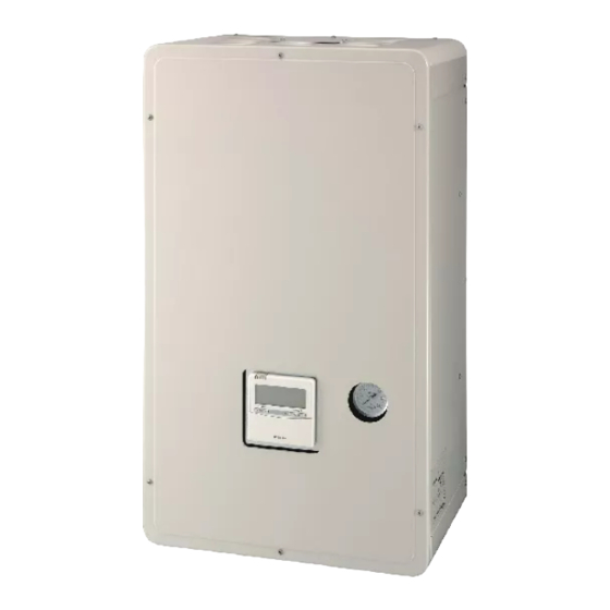
AIR TO WATER HEAT PUMP
Service Manual
Model name:
Hydro unit
HWS-P804XWHM3-E1(TR)
HWS-P804XWHT6-E1(TR)
HWS-P804XWHT9-E1
HWS-P1104XWHM3-E1(TR)
HWS-P1104XWHT6-E1(TR)
HWS-P1104XWHT9-E1(TR)
AMP Air Conditioning
Outdoor unit
HWS-P804HR-E1(TR)
HWS-P1104HR-E1(TR)
www.ampair.co.uk | sales@ampair.co.uk
FILE No. A10-1503
Advertisement
Table of Contents

Related Manuals for Toshiba HWS-P804XWHM3-E1(TR)


Summary of Contents for Toshiba HWS-P804XWHM3-E1(TR)
-
Page 1: Service Manual
FILE No. A10-1503 AIR TO WATER HEAT PUMP Service Manual Model name: Hydro unit Outdoor unit HWS-P804XWHM3-E1(TR) HWS-P804HR-E1(TR) HWS-P804XWHT6-E1(TR) HWS-P1104HR-E1(TR) HWS-P804XWHT9-E1 HWS-P1104XWHM3-E1(TR) HWS-P1104XWHT6-E1(TR) HWS-P1104XWHT9-E1(TR) AMP Air Conditioning www.ampair.co.uk | sales@ampair.co.uk... -
Page 2: Table Of Contents
Contents 1 Safety precautions........... . . 3 2 Refrigerant (R410A) . - Page 3 8 Operational description ..........32 9 Method of defect diagnosis .
-
Page 4: Safety Precautions
Safety precautions The unit and this service guide list very important safety precautions. Understand the following details (indications and symbols) before reading the body text, and follow the instructions. [About indication] Indication Meaning of Indication Indicates that a wrong operation may cause a service engineer and the third persons DANGER around to get fatal or serious injuries. - Page 5 WARNING <No modification> Do not modify the unit. • Do not disassemble or modify the parts also. • A fire, an electric shock, or an injury may occur. <Use specified parts> Use the specified parts (∗) when replacing them. • Using parts other than specified ones may cause a fire or an electric shock. ∗: For details, see the parts price list.
- Page 6 WARNING <Check insulation> After the work is completed, check with an insulating-resistance tester (500V) that the insulation resistance between the live and dead-metal parts is 2 MΩ or higher. • A low insulation resistance may cause a disaster at a customer site due to electrical leakage or an electric shock. <Ventilate>...
-
Page 7: Refrigerant (R410A)
Refrigerant (R410A) This Air to Water Heat Pump adopts a refrigerant HFC (R410A) to prevent destruction of the ozone layer. The working pressure of R410A refrigerant is 1.6 times higher than that of the conventional refrigerant R22.The refrigerant oil is also changed for the new refrigeration. Therefore, during installation or service work, be sure that water, dust, former refrigerant, or refrigeration machine oil does not enter the refrigerant cycle of the new type refrigerant Air to Water Heat Pump. -
Page 8: 2-2.Installing Refrigerant Pipe
2-2. Installing refrigerant pipe 2-2-1. Steel pipe and joint For refrigerant piping, steel pipe and joints are mainly used. Select those comply with JIS (Japanese Industrial Standards) for a service work. Also, use such clean piping materials that less impurities attach to the inside of pipe and joints. -
Page 9: 2-2-2.Processing Of Piping Materials
2-2-2. Processing of piping materials When installing refrigerant pipe, prevent water or dust from entering the pipe, and do not use oil other than lubricant used for Air to Water Heat Pump. Make sure that no refrigerant leak occurs. If piping needs lubrication, use lubricating oil whose water content is removed. After the oil is put in, be sure to seal the container with air proof cover or other covers. - Page 10 Flare connecting procedure and precautions 1) Make sure that the flare and connecting portions do not have any flaw and dust. 2) Correctly align the flared surface and the connecting axis. 3) Tighten the flare with designated torque by means of a torque wrench. The tightening torque for R410A is the same as that for the conventional R22.
-
Page 11: 2-3.Tools
2-3. Tools 2-3-1. Necessary tools In Air to Water Heat Pump using R410A, the service port diameter of packed valve of the outdoor unit is changed to prevent mixing of other refrigerant. To reinforce the pressure resistance, flare dimensions and opposite side dimensions of flare nut (For Ø... -
Page 12: 2-4.Recharging Of Refrigerant
2-4. Recharging of refrigerant Recharge, if necessary, the specified amount of new refrigerant according to the following procedure. Recover the refrigerant, and check that no Open fully the handle of gauge manifold Lo, turn on the refrigerant remains in the refrigerant cycle. vacuum pump, and then perform vacuum evacuating. - Page 13 NOTE • Make sure that the setting is appropriate so that liquid can be charged. • A cylinder with siphon enables liquid to be charged without the cylinder turned upside down. [Cylinder without siphon] [Cylinder with siphon] Gauge manifold Gauge manifold Outdoor unit Outdoor unit Siphon pipe...
-
Page 14: 2-5.Brazing Of Pipes
2-5. Brazing of pipes Type of flux • Non-corrosive flux 2-5-1. Materials of brazing It is generally a compound of borax and boric acid. It is effective when brazing temperature is higher than 800 °C. Silver brazing metal • Active solvent Silver brazing metal is an alloy mainly composed of Most of this type of flux is generally used for silver silver and copper. - Page 15 5) Use the reducing valve to adjust the nitrogen gas flow speed to 0.05 m /hour or 0.02 MPa (0.2 kgf/cm 6) After the steps above, keep the nitrogen gas flowing until the pipe cools down to a certain extent. (Temperature where the pipe is cool enough to be touched by hands) 7) Remove the flux completely after brazing.
-
Page 16: Specifications
Specifications Unit name Hydro unit HWS-P804XWHM3-E1, P804XWHT6-E1, P804XWHT9-E1 Outdoor unit HWS-P804HR-E1 Heating capacity *1 (kW) Cooling capacity *2 (kW) Variable range of compressor frequency 10 - 70 Hz Power source Single phase 50 Hz 220-230 V Operation mode Heating Cooling Electric characteristic *1 *2 Hydro unit Current (A) - Page 17 Unit name Hydro unit HWS-P1104XWHM3-E1, P1104XWHT6-E1, P1104XWHT9-E1 Outdoor unit HWS-P1104HR-E1 Heating capacity *1 (kW) 11.2 Cooling capacity *2 (kW) 10.0 Variable range of compressor frequency 10 - 90 Hz Power source Single phase 50 Hz 220-230 V Operation mode Heating Cooling Electric characteristic *1 *2 Hydro unit...
-
Page 18: Outside Drawing
Outside drawing 4-1. Hydro unit HWS-P804XWHM3-E1, P804XWHT6-E1, P804XWHT9-E1 HWS-P1104XWHM3-E1, P1104XWHT6-E1, P1104XWHT9-E1 2-dia.12x17 long hole (for dia.8-10 anchor bolt) 371.5 72.5 72.5 B leg part Anchor bolt long hole pitch Manometer Remote controller 2-dia.12x17 U-shape hole A leg part (for dia.8-10 anchor bolt) Hot water outlet 19.5 connecting pipe 1 1/4"... -
Page 19: 4-2.Outdoor Unit
4-2. Outdoor unit HWS-P804HR-E1, P1104HR-E1 AMP Air Conditioning www.ampair.co.uk | sales@ampair.co.uk... -
Page 20: 4-3.Hot Water Cylinder
4-3. Hot water cylinder HWS-2101CSHM3-E(-UK) HWS-3001CSHM3-E(-UK) Specification for UK only Specification for UK only HWS-1501CSHM3-E(-UK) Specification for UK only AMP Air Conditioning www.ampair.co.uk | sales@ampair.co.uk... -
Page 21: Wiring Diagram
Wiring diagram 5-1. Hydro unit *Option WARNING Remote Perform the grounding from the controller earth terminal in the terminal (HWS-AMS11E) block of the outdoor unit. Remote Symbol Parts name Symbol Parts name *Option controller Water pump motor Water heat exchanger temperature sensor (HWS-AMS11E) CAUTION 3-way valve (local) -
Page 22: 5-2.Outdoor Unit
5-2. Outdoor unit HWS-P804HR-E1, HWS-P1104HR-E1 Reactor Reactor (Red) (White) (Black) (Gray) (Gray) (White) (White) CN202 P04 P05 CN200 CN201 Fuse T3.15 A 250 V ~ Heater CN703 (Gray) CN400 Fuse FM01 (White) T3.15 A 250 V ~ CN300 P.C. board FM02 (White) CN702... -
Page 23: 5-3.Hot Water Cylinder Unit
5-3. Hot water cylinder unit Double pole thermal cut out Blue Blue Green / Brown Yellow Brown TB03 (230 V) TB06 (TTW) TTW sensor Hot water cylinder heater Supply 220 - 230 V from hydro unit To hydro unit Cable size 1.5 mm (minimum) AMP Air Conditioning www.ampair.co.uk | sales@ampair.co.uk... -
Page 24: Key Electric Component Rating
Key electric component rating 6-1. Hydro unit HWS-P804XWHM3-E1, T6-E1, T9-E1 Model name Component name Type name Rating M3-E1 T6-E1 T9-E1 Circulating pump UPM 2K 25-60 130 AC230 V 0.40 A (MAX) Backup heater 3 kW SA3-23652B AC230 V 3 kW Backup heater 6 kW SA3-23652B AC400 V (3N) 6 kW... - Page 25 HWS-P1104XWHM3-E1, T6-E1, T9-E1 Model name Component name Type name Rating M3-E1 T6-E1 T9-E1 Circulating pump UPM GEO 25-85 130 AC230 V 0.66 A (MAX) Backup heater 3 kW SA3-23652B AC230 V 3 kW Backup heater 6 kW SA3-23652B AC400 V (3N) 6 kW Backup heater 9 kW SA3-23652B AC400 V (3N) 9 kW...
-
Page 26: 6-2.Outdoor Unit
6-2. Outdoor unit HWS-P804HR-E1, P1104HR-E1 Component name Type name Rating Compressor DA422A3F-26M Outdoor fan motor (x2) ICF-280-A100-1 Output 100 W Reactor (x2) CH-44 1.4 mH, 25 A 4-way valve coil AC220 - 230 V full-wave rectifier input, alive time 10 sec or less Pulse motor valve (PMV) coil UKV-A038 DC12 V... -
Page 27: 6-3.Hot Water Cylinder Unit
6-3. Hot water cylinder unit Model name 1501 2101 3001 Component name Type name Rating M3-E M3-E M3-E (-UK) (-UK) (-UK) Hot water cylinder heater – AC230 V 2.7 kW Hot water cylinder temperature 10 kΩ (25 °C) sensor – (TTW sensor) Thermal cut-out Operating temperature... -
Page 28: 6-4.Water Heat Exchange Control Board
6-4. Water heat exchange control board HWS-P804XWHM3-E1, P804XWHT6-E1, P804XWHT9-E1 HWS-P1104XWHM3-E1, P1104XWHT6-E1, P1104XWHT9-E1 TC sensor connector TTW sensor connector CN203 CN214 Low pressure sensor connector PWM signal line Remote controller TFI sensor CN207, CN212 connector connector connector CN500 CN41 CN213 THO sensor connector CN206 TWI sensor connector CN204... -
Page 29: 6-5.Outdoor Control Board
6-5. Outdoor control board HWS-P804HR-E1, P1104HR-E1 Compressor output terminals Electrolytic capacitors Fan motor output (Lower) Fan motor output (Upper) CN202 CN300(White) CN400(White) CN201 CN200 Case thermostat connector CN609(Blue) Power circuit protection fuse F100(250 V, 3.15 A, plastic case) 4-way valve connector CN701(White) Compressor ON output connector... -
Page 30: Refrigeration Cycle / Water System Diagram
Refrigeration cycle / Water system diagram 7-1. Water system diagram AMP Air Conditioning www.ampair.co.uk | sales@ampair.co.uk... - Page 31 Installation example of water circuit The water flowing for a system without buffer tank ((1), (2), (3), (5)) requires18 /min (P804XWH 13 /min) or more. This water flowing requires 5 or more branches of Floor heating or Radiator etc. Less than 5 branches may cause a flow deficiency. In this case, please provide a buffer tank and secondary pumps as shown in (4).
-
Page 32: 7-2.Refrigeration Cycle System Diagram
7-2. Refrigeration cycle system diagram HWS-P804XWHM3-E1, HWS-P804XWHT6-E1, HWS-P804XWHT9-E1, HWS-P1104XWHM3-E1, HWS-P1104XWHT6-E1, HWS-P1104XWHT9-E1 / HWS-P804HR-E1, HWS-P1104HR-E1 Outdoor unit Hydro unit Heating / Hot water supply Expansion vessel Defrosting / Cooling Manometer Low pressure sensor Water vent valve High pressure 2-way valve sensor (PD) Air vent valve 4-way valve Plate-type... -
Page 33: Operational Description
Operational description This chapter describes the working circuit and control of Air to Water Heat Pump about the following operations. Item Page 8-1. Basic Operation 1) Operation control 2) Hot water supply operation 33 to 35 3) Heating operation 4) Cooling operation 8-2. - Page 34 Item Operation flow and applicable data, etc. Operation description 8-1. 1) Operation control 1. Purpose Basic The operations of the Remote controller Operation hydro unit and the outdoor unit are controlled according to Operation Remote controller settings user-defined operation condition selection <Heating>...
- Page 35 Item Operation flow and applicable data, etc. Operation description 8-1. 2) Hot water supply operation Hot water supply operation Basic 1. Purpose Operation Hot water supply [HOT WATER] Hot water temperature: 40 °C to 75 °C 2. Details button set to "ON" This section performs hot water supply operation according to...
- Page 36 Item Operation flow and applicable data, etc. Operation description 8-1. 4) Cooling operation 1. Purpose Basic Cooling Operation 2. Details ZONE1, 2 Cooling temperature: 7 °C to 25 °C This section performs button set to "ON" cooling operation according to cooling conditions specified for Circulation pump "ON/OFF"...
- Page 37 Item Operation flow and applicable data, etc. 8-2. 1) Heat pump operation range of hot water supply, heating and cooling Operation Mode The heat pump operation range of hot water supply, heating and cooling is shown on the figures below. and Control •...
- Page 38 Item Operation flow and applicable data, etc. 8-2. The following shows the operation modes and controlled objects. Operation Mode Operation Heating and Hot water both operate Cooling and Hot water both operate and Control mode Method Heat pump select Heat pump select Heat pump select Heat pump select for hot water...
- Page 39 Item Operation flow and applicable data, etc. 8-2. 3) Heating operation Operation Mode <Operation only for ZONE1> and Control • This operation is enabled when DP_SW12_2 ZONE1 is set to "OFF" (default). Method • The remote controller displays settings, and only the set temperature of can be changed.
- Page 40 Item Operation flow and applicable data, etc. 8-2. 4) Cooling operation Operation Mode Pressing the [ZONE1, 2] button and then [OPERATION MODE] starts a cooling operation. and Control 1) Operation start condition Method Pressing the [ZONE1, 2] button and then [OPERATION Heat pump operation MODE] starts a cooling operation.
- Page 41 Item Operation flow and applicable data, etc. 8-2. Related FC Operation Mode FC No. Setting item Default Setting available range and Control Method Priority mode switch temperature 0 °C -20-20 °C * Note: When user selects “hot water supply” and “ZONE1,2”, and Heat pump selects hot water supply mode, the Maximum operating time of heat pump is 30 min.
- Page 42 Item Operation flow and applicable data, etc. 8-2. 7) Boiler control Operation Mode The boiler assists the hot water supply operation and heating operation according to the boiler’s position. and Control Method 7-1) Boiler setting • TCB-PCIN3E optional PC board is required. Connect its connection cable to CN208 port on the PC board of the hydro unit.
- Page 43 Item Operation flow and applicable data, etc. 8-2. 7-2) Boiler-output control Operation Mode • I zone: heat pump operation and Control Normally the heat pump operation is executed in the zone. Method • J zone: heat pump operation and boiler operation *1 In the zone, the heat pump + boiler operation (*2) is executed and the heater operation is executed in the hot-water- supply side.
- Page 44 Item Operation flow and applicable data, etc. 8-2. Related FC Operation Mode FC No. Setting item Default Variable range and Control Method Boiler-heat pump switching temperature -10 °C -20-20 °C Control priority between the hydro unit and boiler 0: Hydro unit control Independent temperature (Control valid for operating heat pump mode) control for the hydro unit...
- Page 45 Item Operation flow and applicable data, etc. 8-2. 9) Anti bacteria (ANTI BACTERIA) operation Operation Mode An anti bacteria operation regularly performs a Hot water supply operation with the set temperature TSC_H = 75 °C and Control (can be set with FC_0A). Method 1) How to operate •...
- Page 46 Item Operation flow and applicable data, etc. 8-2. 10) Night set back (NIGHT SET BACK) operation Operation Mode A night set back operation performs heating at 5K lower and cooling at 5K higher temperatures against the remote and Control controller set temperature from the setting start time (22:00) to the end time (6:00) every day. Method Note) •...
- Page 47 Item Operation flow and applicable data, etc. 8-2. 12) AUTO operation Operation Mode An auto operation sets the water temperature TSC_F depending on the outside air temperature TO. and Control Method 1) How to operate • Pressing the remote controller [ZONE1, 2] button and then the [AUTO] button starts AUTO operation for heating. •...
- Page 48 Item Operation flow and applicable data, etc. 8-2. 13) Night time low-noise operation Operation Mode A night time low-noise operation reduces operation frequency and the number of outdoor fan rotations for a certain period and Control during night time as noise control for urban operation. Method Maximum operation frequency 40.2 Hz (Hot water supply/Heating/Cooling) Maximum fan tap...
- Page 49 Item Operation flow and applicable data, etc. 8-3. 1) Capacity control (compressor, high-temperature release, low-temperature release) Hydro Unit Control This unit controls the compressor frequency and heater output so that the water outlet temperature matches the remote controller set temperature. 1-1) Compressor control •...
- Page 50 Item Operation flow and applicable data, etc. 8-3. 1-2) Low temperature release control Hydro Unit Control A heat pump operation is performed as shown in the table below according to the TC sensor detecting temperature. • For the detected temperature, TC = TWO of a heat pump operation is used. The values of T7 through T10 varies depending on TWI.
- Page 51 Item Operation flow and applicable data, etc. 8-3. 2) Heater control Hydro Unit Control 2-1) Hot water supply operation During a hot water heat pump operation, the unit energizes the hot water cylinder heater (2.7 kW) when all the following conditions are met. Note that when the hot water supply set temperature (TSC_F) is reached, the unit stops energizing the heater.
- Page 52 Item Operation flow and applicable data, etc. 8-3. 2) Control at the time of heating heater operation Hydro Unit Control • Controlled Object: Backup heater, Booster heater The backup heater control starts when 13 minutes has passed after the heating heat pump operation started. The backup heater control increases, decreases, or maintains the number of heaters every 10 minutes (FC) depending on the difference between the heating set temperature (TSC_F) and the heater outlet temperature (THO).
- Page 53 Item Operation flow and applicable data, etc. 8-3. 2-5) No heater operation Hydro Unit Control According to the DP_SW11 setting, the unit switches the energize / not energize for the hot water cylinder, backup heater, and booster. For details, see 10-1-4. (See page 118) (Caution) All heater should be added to this Air to water system.
- Page 54 Item Operation flow and applicable data, etc. 8-3. 3) Circulation pump control Hydro Unit Control One circulation pump (enhancing pump P2) can be connected to the unit in addition to the built-in circulation pump P1. You can change the settings of the built-in pump P1 and the enhancing pump P2 using DP_SW10-1, 2, and 3 in the hydro unit.
- Page 55 Item Operation flow and applicable data, etc. 8-3. 3-6) Controlling the built-in pump P1 during cooling operation controlled with the room temperature thermostat or room Hydro Unit Control temperature remote controller. Charging the action of the built-in pump P1 by setting FC65. •...
- Page 56 Item Operation flow and applicable data, etc. 8-3. 4) Control by the flow switch Hydro Unit Control Whether water flows or not is judged with the ON/OFF of the flow switch. Model Determined that water flows when: Determined that water does not flow when: HWS-P804**-E1 13L or more water flows per minute Water less than 13L flows per minute...
- Page 57 Item Operation flow and applicable data, etc. 8-3. 6-3) Control method Hydro Unit Control • The water temperature setting at starting operation is 40 °C (FC_9D) at heating and 20 °C (FC_96) at cooling. If the temperature setting calculated by Auto curve at starting operation will be used instead of the fixed temperature 40 °C (FC_9D), FC_B5 should be set to “1”.
- Page 58 Item Operation flow and applicable data, etc. 8-3. 7) Room temperature control with the thermostat Hydro Unit Control You can install a commercially available thermostat to control room temperature. 7-1) Installing the room temperature thermostat • TCB-PCM03E optional PC board is required. Connect its connection cable to CN211 port on the PC board of the hydro unit.
- Page 59 Item Operation flow and applicable data, etc. 8-3. 8) Hot water cylinder thermostat control Hydro Unit Control Hot water can be supplied using an existing hot-water cylinder with a thermostat. 8-1) Installing the hot-water cylinder thermostat • Optional board : TCB-PCM03E optional PC board is required. Connect its connection cable to CN210 port on the PC board of the hydro unit.
- Page 60 Item Operation flow and applicable data, etc. 8-3. 9) Control of force stop and restart Hydro Unit Control The unit can be stopped and restarted with external input. By setting FC52 and FC61 and FCB6, you can set an operation mode to run/stop or can run/stop the unit in the mode assigned on the remote controller. •...
- Page 61 Item Operation flow and applicable data, etc. 8-3. Basic operation logic Hydro Unit Control There are 4 operation combination pattern for Heating & Hot water When open signal is input, the operation status change to the next status. For example, if current operation status is heating ON and hot water OFF, then next status to be heating OFF & hot water OFF when pulse is input Hydro unit memorize the status of the operation pattern before changing OFF status by close signal.
- Page 62 Item Operation flow and applicable data, etc. 8-3. 10) Control of limit of heat pump operation Hydro Unit Control When the peak period of electric power charge is set due to the contract or other conditions, you can limit heat pump operation and give priority to boiler operation using an external input signal.
- Page 63 Item Operation flow and applicable data, etc. 8-3. 13) Q-H characteristics of hydro unit Hydro Unit Control The following shows the Q-H characteristics. 13-1)HWS-P804XWHM3-E1, T6-E1, T9-E1 Hydraulic heat exchanger (8 kW) QH characteristics Minimum flow rate Hydro unit QH- Characteristics (220/230 V) Out of range Pump duty 100 %...
- Page 64 Item Operation flow and applicable data, etc. 8-3. 14) Automatic restart control Hydro Unit Control The unit records operation information before a power outage and retrieves the information after the power is restored to restart automatically the operation with the information. 14-1)Operation during remote controller •...
- Page 65 Item Operation flow and applicable data, etc. 8-3. 15-4)Piping freeze prevention control 4 When the value of Ps sensor is low, freeze prevention is activated regardless of a heat pump operation mode. Hydro Unit Control 1) Determination condition: Low pressure sensor detects PS < 0.2 MPa and 90 seconds passes (defrosting and cooling) (During a defrosting operation for cooling and heating, or hot water supply) Low pressure sensor detects PS <...
- Page 66 Item Operation flow and applicable data, etc. 8-4. 1) PMV (Pulse motor valve) control Outdoor unit Valve opening is controlled using the expansion valve with a pulse motor according to a heat pump operation status. control • PMV is controlled between 30 and 500 pulses during an operation. •...
- Page 67 Item Operation flow and applicable data, etc. 8-4. 3) Current release control Outdoor unit The number of compressor rotation is controlled so that current value of the compressor drive circuit does not exceed the control specified value. • The outdoor unit detects the input current. •...
- Page 68 Item Operation flow and applicable data, etc. 8-4. 4) Current releases shift control Outdoor unit During a cooling operation, this control prevents the electronic parts, such as a compressor drive element, and control compressor from failing. • The current release control value (I) is selected from the following table according to the TO sensor value. Current release control value (I) Temperature range P804HR-E1, P1104HR-E1...
- Page 69 Item Operation flow and applicable data, etc. 8-4. 5-2) Hot water supply and heating fan control Outdoor unit control 1) The TE sensor, TO sensor and operation frequency control the outdoor fan. (The minimum W1 to the maximum are controlled according to the table below.) 2) For 3 minutes after the start, the maximum fan tap for each zone that is shown in the following table is fixed.
- Page 70 Item Operation flow and applicable data, etc. 8-4. 6) Defrosting control Outdoor unit 6-1) Defrost operation control This control defrosts the outdoor heat exchanger. The temperature sensor (TE sensor) of the outdoor heat exchanger determines frost formation, and then defrosting is performed in the 4-way valve reverse defrosting method. 1) During a heating operation, defrosting is performed when the TE sensor meets any of the conditions in A through D zones.
- Page 71 Item Operation flow and applicable data, etc. 8-4. Jumper switching O: Short circuit ×: Open Outdoor unit control J805 J806 150 min (Factory default) × 90 min × 60 min × × 30 min 6-2) Advance defrost operation When compressor temperature is low, defrosting preliminary operation will be carried out to carry defrosting smoothly in effect.
- Page 72 Item Operation flow and applicable data, etc. 8-4. 7) Winding heating control Outdoor unit 1) This control energizes the inactive compressor instead of the case heater to warm the compressor. The purpose is control to prevent the refrigerant from staying inside the compressor. 2) After the unit is installed, failure to perform energization for the given time period may cause the compressor to fail.
- Page 73 Item Operation flow and applicable data, etc. 8-4. 10) High pressure release control Outdoor unit 1) To prevent excessive high pressure rise, operating frequency is controlled by the PD sensor. control 2) If the PD sensor detects an abnormal stop zone pressure, the compressor stops and the abnormality detection counter increments.
- Page 74 Item Operation flow and applicable data, etc. 8-4. 13) 2-way valve control Outdoor unit To control the bypass 2-way valve, reducing the minimum capacity and reducing the pressure increase purpose. control Bypass circuit is connect the discharge pipe and the suction pipe of the compressor. 1)Bypass operation start condition The operation start in the following cases.
-
Page 75: Method Of Defect Diagnosis
Method of defect diagnosis In order to diagnose the defective part of the heat pump system, first understand the symptom of the defect. (1) Check the operation status. (It does not move, or it moves but stops, etc.) (2) Flashing display on the display part of the hydro unit. (3) Check the “check code”... -
Page 76: 9-1-1.Check The Power Supply Voltage
9-1. Matters to be confirmed first 9-1-1. Check the power supply voltage Check that the power supply voltage is AC220-230 V± 10% (signal phase). If the power supply voltage is not in this range, it may not operate normally. 9-1-2. Check for any miswiring of the connection cables between the hydro unit and the outdoor unit The hydro unit and the outdoor unit are connected with three connection cables. -
Page 77: 9-3.Outline Of The Determination Diagram
9-3. Outline of the determination diagram The first determination of whether a defective part is in the hydro unit or the outdoor unit can be performed by the following method. 9-3-1. Procedure of defect diagnosis In the case of a defect, please apply the following procedure in order to find the defective part. Confirm the check Check code Defect in Hydro unit... -
Page 78: 9-3-4.How To Diagnose By Error Code
9-3-4. How to diagnose by error code Defect mode detected by the water heat exchange O ... Possible × ..Not possible Diagnostic functional operation Number of Check abnormalities Detailed Determination and action code Backup Automatic item Operational cause operation reset confirmation Pump or flowing quantity error... - Page 79 Diagnostic functional operation Number of Check abnormalities Detailed Determination and action code Backup Automatic item Operational cause operation reset confirmation Combination error × Model name of the Hydro unit is 1. Check DP_SW13_4 is set to "ON". — different. Low pressure sensor operation error 1.
- Page 80 Diagnostic functional operation Number of Check abnormalities Detailed Determination and action code Backup Automatic item Operational cause operation reset confirmation TTW sensor error Heating × 1. Check the resistance value and Open or short circuit in the hot water connection of the hot water cylinder cylinder sensor.
- Page 81 Defect mode detected by the outdoor unit O ... Possible × ..Not possible Diagnostic functional operation Number of Check abnormalities Detailed Determination and action code Backup Automatic item Operational cause operation reset confirmation TD sensor error 1. Check the resistance value and ×...
- Page 82 Diagnostic functional operation Number of Check abnormalities Detailed Determination and action code Backup Automatic item Operational cause operation reset confirmation Operation of case thermostat 1. Check the refrigeration cycle (gas leak). When the case thermostat exceeds 2. Check the case thermostat and 125 °C.
- Page 83 Diagnostic functional operation Number of Check abnormalities Detailed Determination and action code Backup Automatic item Operational cause operation reset confirmation High pressure protection operation 1. Check that the service valve is fully open. When an abnormal stop occurs due to 2.
- Page 84 Defect mode detected by the remote controller Diagnostic functional operation Check code Determination and action Status of air- Operational cause Condition conditioning No communication between hydro Stop – Defect in the remote controller power unit an remote controller supply displaying at •...
-
Page 85: 9-4.Diagnosis Flow Chart For Each Error Code
9-4. Diagnosis flow chart for each error code 9-4-1. Hydro unit failure detection [A01] Error Pump flow determination [A01] occurs Operation restarts No (No pump sound) Pump rotates Perform Flow switch is Connect flow switch air vent connected to board connector to board Excess air noise comes from inside... - Page 86 [A02] Error Temperature rise and error short circuit Start (TWI,TWO,THO ≥ 70 °C) TWI, TWO, and THO Replace TWI, TWO, sensor characteristics are and THO sensors correct Flow switch is normal Replace flow switch Water outlet temperature is 70 °C or higher Hot water from Correct water circuit...
- Page 87 [A03] Error Temperature rise and error short circuit Start (TTW ≥ 85 °C is detected) TTW sensor Replace TTW sensor characteristic is correct Hot water cylinder heater is energized Mg-sw (RY05) for Replace Mg-sw heater operates Operating noise at normal time At normal temperature, tank thermostat is energized...
- Page 88 [A04] Error Freeze prevention control When the outside temperature and inlet water temperature is low (approx. 20 °C or lower) and the room load is large (operation frequency ≥ rating), the freeze prevention control may be activated. Start Operation restart Perform air vent Secure water...
- Page 89 [A05] Error Piping freeze prevention control Restart 4, TWO 4, or 4 is detected Circulation pump keeps being energized or 3 minutes passed after the start Water heat Set water heat board exchange control board DPSW11-1 to ON DPSW11-1 is ON Backup heater terminal has 220-230 V (±...
- Page 90 [A08] Error Low pressure sensor lowering operation failure (Cooling / Defrosting operation) Start Flow switch is normal Replace flow switch Remove sufficiently excess air Excess air Secure water Waste stuck inside noise comes from Remove waste circulation amount water circuit inside pump 12 M or longer water Place buffer tank and...
- Page 91 [A09] Error Overheat prevention thermostat failure (Hot water supply / Heating operation) Start Put water into water circuit Water cycle contains water (Recommended: 1 - 2 Bar) Replace flow switch Flow switch is normal At normal temperature, Replace heater unit overheat preventive thermostat exchanger air vent valve is normal...
- Page 92 [A10] Error Freeze prevention control (2) (Cooling only) Start Flow switch is normal Replace flow switch Remove sufficiently excess air Excess air Secure water Waste stuck inside noise comes from Remove waste water circuit circulation amount inside pump 12 M or longer water Place buffer tank and pipe to a branch, the second pump...
- Page 93 [A11] Error Release protection operation Start Flow switch is normal Replace flow switch Remove sufficiently excess air Excess air Waste stuck inside Secure water noise comes from Remove waste circulation amount water circuit inside pump 12 M or longer water Place buffer tank and pipe to a branch, the second pump...
- Page 94 [A12] Error Heating or Hot water supply heater failure Restart Operation starts under 10 ≤ TWI 20 °C Freeze prevention control is detected once Heater backup operation Heating: Booster heater Hot water supply: Hot water cylinder heater After 1 hour since heater operation started, neither TWI ≥...
- Page 95 [E04] Error Outdoor unit operates Hydro unit Internal wiring and Correct wiring and connecting wire (1, 2, 3) connecting wire are correct CN04 connector Correct connector and and terminal block (1, 2, 3) wiring terminal block wiring are normal When power is Check water heat exchanger board on again, D502 (Amber LED)
- Page 96 [F04] Error TD sensor failure Start TD sensor Correct TD sensor connector (CN603) is connection connected TD sensor Replace TD sensor resistance characteristic is normal Replace water heat exchange control board [F06] Error TE sensor failure Start TE sensor Correct TE sensor connector (CN601) is connection connected...
- Page 97 [F08] Error TO sensor failure Start TO sensor Correct TO sensor connector (CN602) is connection connected TO sensor resistance characteristic Replace TO sensor (Refer to Characteristic table on page 113) is normal Replace water heat exchange control board [F10] Error TWI sensor failure Start TWI sensor Correct TWI sensor...
- Page 98 [F14] Error TTW sensor failure Start TTW sensor Correct TTW sensor connector (CN214) is connection connected TTW sensor Replace TTW sensor characteristic is normal (Refer to Characteristic table on page 113) Replace water heat exchange control board [F17] Error TFI sensor failure Start TFI sensor Correct TFI sensor...
- Page 99 [F19] Error THO sensor detach failure Start THO sensor Attach THO sensor is attached to pipe to pipe THO sensor Replace THO sensor characteristic is normal (Refer to Characteristic table on page 113) TWO sensor Replace TWO sensor characteristic is normal (Refer to Characteristic table on page 113) Replace water heat exchange control board AMP Air Conditioning...
- Page 100 [F20] Error TFI detach failure Start Mixing valve is attached. Attach a mixing valve. Make the mixing valve Mixing valve connection (Refer to wiring diagram of hydro unit on is correct. connection correct. page 20) Mixing valve setting Make the mixing valve is correct.
- Page 101 [F23] Error Low pressure sensor detach failure Start Lo pressure sensor Attach low pressure sensor is detached (CN207, 212) When operation is stopped, lo pressure sensor Replace low pressure sensor is normal *1 Replace water heat exchange control board *1 How to determine: When operation is stopped [F29] Error EEPROM failure A failure is detected in the IC10 non-volatile memory on the water heat exchanger board during a hot water supply unit operation.
- Page 102 [L09] Error Hydro unit capacity Set indoor unit capacity data is not set Setting item code (FC_01) 8 kW = 12 11 kW = 15 Water heat exchange control board (MCC-1511) Check If defective, replace it [L16] Error In DP_SW12-2, 3 of main unit water heat exchanger, if ZONE1 is not set and ZONE2 is set, [L16] displays abnormality.
-
Page 103: 9-4-2.Outdoor Unit Failure Detection
9-4-2. Outdoor unit failure detection Diagnosis procedure for each check code • One check code may indicate multiple symptoms. In such a case, see the LED indication on the outdoor board to narrow down the check details. • The handy remote controller displays a check code only when the same failure repeatedly occurs while the LED on the outdoor board indicates an error even if it occurs only once. - Page 104 Outdoor LED Check and Action procedure Check code indication (No specific description indicates outdoor unit parts.) [H02] <Indication 1> <Indication 2> [Compressor lock] Power voltage is normal. Improve power line AC220-230 V±10 % Wiring connection is normal. Check and correct Compressor lead (board side, wiring connection compressor side) reactor, power lead...
- Page 105 Outdoor LED Check and Action procedure Check code indication (No specific description indicates outdoor unit parts.) [L10] <Indication 1> <Indication 2> [Model not set] Only when service board is used Cut jumper line by following the instruction comes with the service board package [L15] <Indication 1>...
- Page 106 Outdoor LED Check and Action procedure Check code indication (No specific description indicates outdoor unit parts.) [P05] <Indication 1> <Indication 2> [Power source failure (voltage defective, open phase)] Power voltage abnormal drops or rise Check electric work (AC220-230 V±10 %: single phase) PC board Check outdoor control board P804HR-E1,...
- Page 107 Outdoor LED Check and Action procedure Check code indication (No specific description indicates outdoor unit parts.) [P15] <Indication 1> <Indication 2> [Gas leakage detection] No gas leakage. Correct defective portion Appropriate refrigerant amount. Re-charge refrigerant Correct defective portion Pulse motor valve is normal. Replace defective parts Open fully service valve Service valve is fully opened.
- Page 108 Outdoor LED Check and Action procedure Check code indication (No specific description indicates outdoor unit parts.) [P19] <Indication 1> <Indication 2> [4-way valve invert failure] 4-way valve operates normally. (Check piping temperature at the time of cooling/heating operation) Temperature sensor check TE sensor CN601 TS sensor CN600 Hydro TWO sensor...
- Page 109 Outdoor LED Check and Action procedure Check code indication (No specific description indicates outdoor unit parts.) [P20] <Indication 1> <Indication 2> [Hi pressure protection operation] Open fully service valve Service valve is fully opened. Heating season Heating operation Reset the power source and perform a trail operation according to the season.
- Page 110 Outdoor LED Check and Action procedure Check code indication (No specific description indicates outdoor unit parts.) [P22] <Indication 1> <Indication 2> [Blower system failure] Power voltage is normal Check wiring (AC220-230 V±10 %: single phase) Request power source repair When not energized, the fan motor can be smoothly rotated by hand.
- Page 111 Outdoor LED Check and Action procedure Check code indication (No specific description indicates outdoor unit parts.) No code <Indication 1> <Indication 2> [Discharge abnormality] Compressor's loss of synchronism due to rapid load change, etc. * Although the outdoor LED indicates abnormality, the compressor restarts and no abnormality is confirmed.
- Page 112 Outdoor LED Check and Action procedure Check code indication (No specific description indicates outdoor unit parts.) [F08] <Indication 1> <Indication 2> [Outside air temperature sensor (TO) failure] Correct TO sensor TO sensor connector (CN602) connection is connected TO sensor resistance Replace TO sensor characteristic is normal See the...
- Page 113 Outdoor LED Check and Action procedure Check code indication (No specific description indicates outdoor unit parts.) [F24] <Indication 1> <Indication 2> [High pressure sensor (PD) failure] Correct PD sensor PD sensor connector (CN606) connection is connected PD sensor is normal Replace PD sensor Replace outdoor control board [F31]...
-
Page 114: 9-4-3.Temperature Sensor, Temperature-Resistance Characteristic Table
9-4-3. Temperature sensor, temperature-resistance characteristic table TC, TWI, TWO, TFI, TTW, TE, TS, TO sensors TD, TL sensors Typical value Typical value Ω Ω Resistance value (k Resistance value (k Temperature Temperature (°C) (°C) (Minimum) (Standard) (Maximum) (Minimum) (Standard) (Maximum) 55.73 55.42 60.04... -
Page 115: 9-5.Operation Check By Pc Board Switch
9-5. Operation check by PC board switch 9-5-1. Operation check mode This mode allows to check the operations of the water 2-way valve, water 3-way valve, mixing valve, and circulating pump. This operation is valid when the hydro unit and the outdoor unit are turned on the power. Operation check mode (1) Preparation 1) Turn all of the remote controllers "OFF"... -
Page 116: 9-6.Brief Method For Checking The Key Components
9-6. Brief method for checking the key components 9-6-1. Hydro unit Component name Check procedure Water heat exchange Remove the connector and measure the resistance value with a tester. (Normal temperature) temperature (TC) sensor Temperature 0 °C 10 °C 20 °C 30 °C Water inlet temperature Sensor... -
Page 117: 9-6-2.Outdoor Unit
9-6-2. Outdoor unit Component name Check procedure Compressor Measure the resistance value of each winding with a tester. Type Resistance Location DA422A3F-26M value − 1.04-1.16 Ω White − 1.04-1.16 Ω White Black − 1.04-1.16 Ω At 20 °C Black White Black Outdoor fan motor Measure the resistance value of each winding with a tester. - Page 118 Component name Check procedure Suction temperature (TS) sensor Remove the connector and measure the resistance value with a tester. Heat exchange temperature 10-20 kΩ (Normal temperature) (TE) sensor Temperature Outdoor temperature (TO) 0 °C 10 °C 20 °C 30 °C Sensor (kΩ) sensor Outdoor heat exchange temperature sensor (TE)
-
Page 119: Hydro Unit And Outdoor Unit Settings
Hydro unit and outdoor unit settings Hydro unit 1. Hydro unit Setting 1-1. Setting switch names and positions SW01 SW12 SW13 SW02 SW11 SW07 SW10 SW06 1-2. SW02 (System switching 1) SW02 Switching details Factory default Remarks Boiler install position After 3WV heating side / Before 3WV After 3WV, Before 3 WV 02_1... - Page 120 1-6. SW13 (System switching 3) SW13 Switching details Factory default Remarks 13_1 3WV SPST/SPSD Specification switching SPST 13_2 Boiler output enabled 13_3 Auto Restart of power outage after system power failure. 13_4 – – 2. Hydro unit Function Code Setting 2-1.
- Page 121 Function code table Item Details Factory default Water heat exchanger capacity *1 0012: P804XWH**-E1 0015: P1104XWH**-E1 Depends on type Cooling/Non-cooling switching 0000: Cooling 0001: Not cooling 0000: Cooling Hot Water Boost operation time (operating time) 0003: 30 min 0018: 180 min 0006: 60 min Hot Water Boost set temperature 0040: 40 °C...
- Page 122 Item Details Factory default External input contact logic (must be used in with 0000: CLOSE to stop system *2 0000:CLOSE to stop FC61) 0001: OPEN to stop system *2 0002: OPEN to stop system, CLOSE to restart system (Statics input) 0003: CLOSE to stop system, CLOSE again to restart system (plus input) Logic of 3-way valve’s action when powered (Single...
- Page 123 Item Details Factory default Set temperature E' with outside temperature of 20 °C 0020: 20 °C 0060: 60 °C 0020: 20 °C HP restart water temperature in A zone. (Valid only 0020: 20 °C 0037: 37 °C 0025: 25 °C room temp control using 2nd remote controller) Initial water temperature setting method when 0000: The fixed temperature by FC9D...
- Page 124 2-3. How to reset hydro function code If the hydro unit PCB has been replaced, it is necessary to change the FC 01 (capacity setting) (1) Preparation 1) Turn all of the remote controllers "OFF" for the hot water supply [HOTWATER] and heating [ZONE1,2]. 2) Turn off the power supply of the hydro unit and the outdoor unit.
- Page 125 3. Test run <Procedure> A test run is available with an actual operation in progress or stopped. A test run is available in any of the hot water supply, heating, or cooling mode. The compressor starts according to the test run frequency. A test run automatically stops after 30 minutes at the longest if not stopped with the remote controller.
- Page 126 4. Auto Curve Setting FC code setting can make flexible Auto-Curve settings. <Preparation> Press the TEST and SET and SELECT buttons at the same time for 4 seconds or longer. (See display (Make sure that no operation is in progress.) Specify an item code (FC) from among 29 to 2F with the TEMP.
- Page 127 • Auto-Curve temperature shift Without Auto-Curve individually set, the set temperature can be shifted in the range of ±5k of the current setting. (The set temperature is valid only when Auto operation is in progress. It also applies to Zone 2.) Press the AUTO TEMP button for 4 seconds or longer.
- Page 128 6. Scheduled Operation Setting Schedule setting makes the following modes to be flexibly set: hot water supply, heating, cooling, hot water supply and heating, hot water supply and cooling, and stop, and set temperature. 6-1. How to set scheduled operation <Preparation>...
- Page 129 6-2. How to start and cancel schedule operation <Operation start> Without schedule operation set, press the remote controller SCHEDULE button. blinks. Pressing the SET button during the 5-second blinking changes to lit, and the schedule operation starts. <Operation cancel> With schedule operation set, press the remote controller SCHEDULE button.
- Page 130 8. NIGHT Operation Setting For night time hours, this setting changes set temperature of heating or cooling by 5k as save operation. Press the ZONE1,2 button to start a heating or a cooling operation. (See display (Night time operation is not available for hot water supply. Use the schedule operation.) Pressing the NIGHT button displays the...
- Page 131 9. Anti Bacteria Setting This setting regularly raises the hot water cylinder temperature to prevent bacteria from growing. Press the HOT WATER button to start a hot water supply operation. (Normal hot water supply operation) (No anti bacteria setting is provided to heating and cooling.) Pressing the ANTI BACTERIA button displays the symbol.
- Page 132 10. Hot Water Boost Setting This setting heats the water whenever necessary by using the heat pump and hot water cylinder heater. Press the HOT WATER button to start a hot water supply operation. (Normal hot water supply operation) Pressing the HOT WATER BOOST button displays the symbol.
- Page 133 12. Forced Defrosting Setting The FC code setting (See 10-2-2 (See page 119)) can activate the forced defrosting mode for the outdoor unit operation. (Preparation) Press the remote controller buttons, TEST , SET and SELECT , at the same time for 4 seconds or longer.(Make sure that no operation is in progress.) Specify CODE NO.
- Page 134 13. Display Function of Set Temperature and Other Settings ■ Sensor temperature display calling <Details> This function calls the service monitor mode from the remote controller to show the data of the remote controller, the hydro unit, and outdoor unit. <Procedure>...
- Page 135 14. Failure History Calling Function <Details> This function calls the previous failure details. <Procedure> Press the TEST and SET buttons at the same time for 4 seconds or longer to call the service check mode. The service check lights up with CODE No. "01" displayed at first, and the latest warning detail is displayed.
- Page 136 Outdoor unit 15. Outdoor Unit Setting 15-1. Refrigerant recovery control Although HFC refrigerant is "Ozone depletion potential = 0", emission control is applied to it as a greenhouse effect gas. This model has a switch for the outdoor unit to perform an environment-friendly refrigerant recovery operation (pump down) when the model is replaced or discarded.
- Page 137 15-2. Outdoor unit settings (Existing piping, Power save, etc.) The following settings are available with dip switch setting and jumper wire setting. Function Where to set Control details Existing piping When using a Ø19.1 pipe for the existing piping, set the switch to ON. setting This case may decrease heating capacity depending on the outside air SW802...
- Page 138 15-3. Service support functions (LED indication, Switch operation method) The following settings are available with dip switches. (1) Overview Using 3 dip switches (SW802, SW803, SW804) and 2 push-button switches (SW800, SW801) can make settings available and confirm operations. For operation Part number Specification Operation details...
- Page 139 (2) LED indication switching (SW800, SW803 operation) (2) -1. Indication switching list Operating SW803 can switch the indications of LED D800 to D804 on the outdoor control board. Switch Function and details Abnormality indication (Current abnormality) This switch indicates the current abnormality. SW803 Without an abnormality, the lights are off.
- Page 140 (2) -2. Abnormality indication The current abnormality and the latest abnormality (including the current one) can be identified by the LED D800 to D804 on the outdoor control board. 1) Setting all the SW803 dip switches to OFF indicates the current abnormality status. 2) Setting SW803 dip switch <1>...
- Page 141 (2)-3. Sensor, Current, Compressor operation frequency, PMV position indication The values detected by controller, such as temperature sensor or current values, can be easily checked. Legend) ---- ---- Light Item setting Temperature sensor ( Current Compressor PMV position operation (pulse) frequency (r.p.s.) SW803...
- Page 142 (3) Special operation for maintenance and inspection (SW801, SW804) SW801 and SW804 can perform the following special operations for maintenance and inspection. 1) Switches the dip switch SW804. (See the table below) 2) Presses the push-button switch SW801 for approx. 1 second. 3) Starts the functions shown below.
- Page 143 SW804 Operation when press button switch SW801 is pressed Self-holding valve vacuum operation (Switch to heating cycle) SW804 (RY700, RY701, RY705, CN701 for check) Sets relay RY700, RY701, and RY705 to ON. (CN701 Between 1 to 4 Voltage = Approx. 325V) This function operates for 10 seconds.
-
Page 144: Replacement Of The Service Pc Board
Replacement of the service PC board Setting the jumper wires and DIP switches Outdoor unit Service Parts (CDB) HWS-P804HR-E1, P1104HR-E1 302-6V-045 (MCC-1571) Parts name Function Setting Jumper wire J800~J803 Model switching Cut these jumper wires according to the following table. J804~J811 Settings Set these jumper wires to the settings of the PC board... -
Page 145: How To Exchange Main Parts
How to exchange main parts WARNING <Turn off the power breaker> Because the electrical components are energized with high voltage, always turn off the power breaker before starting to work. <Check> Ensure that no water pressure is present when replacing the water circuit (water pump, heater unit, flow switch, etc). After a repair is complete, perform a test run (after attaching the front panel, upper and lower cabinets, and side cabinet) and check that no abnormality including smoke or abnormal noise occurs. - Page 146 Exchange parts name Work procedure Remarks Remote controller 1.How to remove 1) Perform the step 1-1. 2) Remove the remote controller from the holder using a flat-blade screwdriver. (Release the stopper.) Remote 3) Disconnect the remote controller cable from the controller holder terminal block on the back side of the remote controller.
- Page 147 Exchange parts name Work procedure Remarks Relay board 1. How to remove MCC-1431 1) Perform the step 1-1. 2) Disconnect the connectors and lead cables connected to other parts from the relay board. 1. Connector CN01: TB 01 3P Terminal block (3P: White) CN02: Water heat exchanger board (5P: White) CN10: TB 05 9P Terminal block (9P: White) NOTE...
- Page 148 Exchange parts name Work procedure Remarks Side board 1. Side board (Right) Side board (Right) 1) Perform the step 1-1-1), 2), 3). 2) Remove the fixed screws of the side board (Right). (ST1T Ø4 × 10, 5 screws) 3) Remove the fixed screws of the side board (Right) and the manometer fixing board.
- Page 149 Exchange parts name Work procedure Remarks Expansion vessel To replace a water circuit part, first close the water Expansion vessel Expansion vessel Expansion vessel supply source valve and the valve of water pipe connected to the hydro unit. 1) Perform the step 1-1, step 5. 2) Remove the fixed band of the expansion vessel.
- Page 150 Exchange parts name Work procedure Remarks Pump To replace a water circuit part, first close the water Pump Pump Pump supply source valve and the valve of water pipe fixing fixing fixing board board board connected to the hydro unit. 1.
- Page 151 Exchange parts name Work procedure Remarks Flow switch To replace a water circuit part, first close the water supply source valve and the valve of water pipe connected to the hydro unit. 1. How to remove 1) Perform the step 1-1 and step 5. 2) Remove the flow switch.
- Page 152 Exchange parts name Work procedure Remarks Heater assembly To replace a water circuit part, first close the water supply source valve and the valve of water pipe connected to the hydro unit. 1. How to remove 1) Perform the step 1-1, step 5, 6, 7, and 11. 2) Remove the nut of the heater connection.
- Page 153 Exchange parts name Work procedure Remarks Water heat • Close the water piping source valve and the valve exchanger assembly of water pipe connected to the hydro unit, and Water Water Water then remove the refrigerant and water piping. piping fixing piping fixing piping fixing •...
- Page 154 2. Outdoor Unit HWS-P804HR-E1, P1104HR-E1 Exchange parts Work procedure Remarks name Common procedure NOTE Front panel Wear gloves when performing the work. Failure to do so may cause an injury when accidentally contacting the parts. 1. How to remove 1) Stop the operation by remote controller and turn off the breaker.
- Page 155 Exchange parts Work procedure Remarks name Outlet cabinet How to remove Outlet cabinet Heat exchanger 1) Perform the step 1-1. 2) Remove the screws of the outlet cabinet and Motor base Paring board parting board. (ST1T Ø4 × 8, 4 screws) 3) Remove the screws of the outlet cabinet and bottom board.
- Page 156 Exchange parts Work procedure Remarks name Electric parts 1. Control board Control board Fan motor (upper) replacement 1) Perform the step 1-1. Compressor Reactor lead case connector A WARNING thermostat For 1 minute after the power is turned off, do not disassemble the inverter to prevent an electric shock.
- Page 157 Exchange parts Work procedure Remarks name Electric parts 2. Reactor Binding tie Reactor lead replacement 1) Perform the step 1-1. (Compressor lead) connector A 2) Remove the reactor lead connected to the control Control board board. Reactor lead connector A, B 3) Cut the binding tie that binds the compressor leads and fan motor leads.
- Page 158 Exchange parts Work procedure Remarks name Fan motor 1) Perform the step 1-1 and step 2. Turn it right Propeller fan 2) Remove the fan motor and the flange nut that fixes to loosen the propeller fan. • To loosen the flange nut, turn it clockwise. (Turn it counter clockwise for tightening.) 3) Remove the propeller fan.
- Page 159 Exchange parts Work procedure Remarks name Compressor 1. Remove defective compressor Piping panel (Front) Compressor lead 1) Perform refrigerant gas recovery. 2) Perform the step 1-1 and step 3. 3) Remove the piping panel (Front). Remove screws of the piping panel (Front) and bottom board.
- Page 160 Exchange parts Work procedure Remarks name Compressor 2. Attach the compressor Wind ferrite core with Compressor lead 1) Attach the compressor in the reverse order of the compressor lead removal. Compressor lead for 4 times NOTE • Be sure to replace the compressor lead after the compressor replacement.
- Page 161 Exchange parts Work procedure Remarks name Pulse motor valve coil 1. How to remove 1) Perform the step 1-1. Recess Pulse motor valve body 2) Remove the coil from the pulse motor valve body by pulling upward while rotating the coil. 2.
- Page 162 Exchange parts Work procedure Remarks name Bottom plate heater 1. Detachment 1) Recover the refrigerant. (See 15-1. Refrigerant recovery control) Drain the water in the hydro unit before refrigerant recovery. 2) Execute steps 1-1, 2, and 3. 3) Detach the two fin guards. (9 pcs.
-
Page 163: For Cooling Installation
For cooling installation If user install the Hydro unit to place humidity location or high humidity region, also user use cooling mode, please attach moisture- proof parts which parts are contained in Hydro unit. Hydro unit • Stick the optional insulator for cooling to the bottom of the Hydro Unit. -
Page 164: Periodic Inspection Items
Periodic inspection items For a long-term safe operation of this equipment, perform periodic inspection and parts replacement. <Inspection items> Hydro unit Frequency Periodic inspection details (HWS-P804**-E1, P1104**-E1) 1. Insulation measurement (Power source circuit / Annually Insulation measurement with a mega tester Heater circuit) 2. -
Page 165: Part Exploded View, Part List
Part exploded view, part list Hydro Unit AMP Air Conditioning www.ampair.co.uk | sales@ampair.co.uk... - Page 166 E-P-Box Assembly (Hydro Unit) AMP Air Conditioning www.ampair.co.uk | sales@ampair.co.uk...
- Page 167 43160579 TERMINAL 43160561 TERMINAL, 4P 43050425 SENSOR ASSY, SERVICE 43150320 SENSOR ASSY, SERVICE 43160568 TERMINAL, 2P 37517875 MARK, ESTIA 37517876 MARK, TOSHIBA FOR ESTIA 43160571 FUSE, HOLDER 15A 250V 43F6A156 FUSE (ET), 3.15A AC250V AMP Air Conditioning www.ampair.co.uk | sales@ampair.co.uk...
- Page 168 Outdoor Unit (HWS-P804HR-E1, P1104HR-E1) AMP Air Conditioning www.ampair.co.uk | sales@ampair.co.uk...
- Page 169 COIL, PMV, UKV-A038 4314Q031 STRAINER 4314Q032 STRAINER 43160591 LEAD ASSY, COMPRESSOR 43194029 BONNET, 5/8 IN 37517884 MARK, TOSHIBA FOR ESTIA 4314N038 COIL, SOLENOID, AC220-2 40 50HZ 43146711 VALVE, 2-WAY 43160571 FUSE, HOLDER, 15A 250V 43F6A156 FUSE(ET), 3.15A, AC250V 37545716 HEATER ASSY...
- Page 170 Inverter Assembly (HWS-P804HR-E1, P1104HR-E1) AMP Air Conditioning www.ampair.co.uk | sales@ampair.co.uk...
- Page 171 Number of pieces per unit Safety Ref. No. Part No. Description HWS-P804HR-E1 HWS-P1104HR-E1 43050425 SENSOR ASSY, SERVICE 43F63325 HOLDER, SENSOR (TE) 43150319 SENSOR ASSY, SERVICE 43158190 REACTOR 43160565 TERMINAL BLOCK, 3P, 20A 43160581 TERMINAL 43160589 FUSE 43163055 HOLDER, SENSOR 43163059 SPACER, BUSH 43163060 SPACER, COLLAR...
- Page 172 Copyright © 2014 TOSHIBA CARRIER CORPORATION, ALL Rights Reserved. AMP Air Conditioning www.ampair.co.uk | sales@ampair.co.uk...
Need help?
Do you have a question about the HWS-P804XWHM3-E1(TR) and is the answer not in the manual?
Questions and answers