Westermo Lynx L108-F2G-S2 User Manual
Industrial ethernet 8-port device server switch
Hide thumbs
Also See for Lynx L108-F2G-S2:
- User manual (36 pages) ,
- User manual (32 pages) ,
- User manual (25 pages)

Related Manuals for Westermo Lynx L108-F2G-S2


Summary of Contents for Westermo Lynx L108-F2G-S2
- Page 1 www.wester mo.com Lynx L108/208-F2G-S2 Industrial Ethernet 8-Port Device Server Switch...
-
Page 2: Table Of Contents
Table of Contents 1. General Information ................ 4 1.1. Legal Information ..............4 1.2. About This Guide ..............4 1.3. Software Tools ..............4 1.4. License and Copyright for Included FLOSS ......... 4 1.5. WeOS Management Guide ............4 2. Safety and Regulations ..............5 2.1. - Page 3 4.6. Factory Default ..............24 5. Specifications ................26 5.1. Interface Specifications ............26 5.2. Type Tests and Environmental Conditions ......... 30 6. Revision Notes ................33 Lynx L108/208-F2G-S2...
-
Page 4: General Information
Westermo reserves the right to revise this document or withdraw it at any time without prior notice. Under no circumstances shall Westermo be responsible for any loss of data or income or any special, incidental, and consequential or indirect damages howsoever caused. -
Page 5: Safety And Regulations
2. Safety and Regulations 2.1. Warning Levels Warning signs are provided to prevent personal injuries and/or damages to the product. The following levels are used: Level of warning Description Consequence Consequence personal injury material damage Indicates a potentially Possible death or major Major damage to the hazardous situation injury... -
Page 6: Safety Information
PROTECTIVE FUSE It must be possible to disconnect manually from the power supply. Ensure compliance to national installation regulations. Replacing the internal fuse must only be performed by Westermo qualified personnel. POWER SUPPLY CONNECTION There are safety regulations governing the power source that can be used in conjunction with the product. - Page 7 REDUCE THE RISK OF FIRE To reduce the risk of fire, use only telecommunication line cords with a cable diameter of AWG 26 or larger. Regarding power cable dimensions, see chapter Interface Specifications. CLASS 1 LASER PRODUCT Do not look directly into a fibre optical port or any connected fibre, although the product is designed to meet the Class 1 Laser regulations and complies with 21 CFR 1040.10 and 1040.11.
-
Page 8: Care Recommendations
If the product is not working properly, contact the place of purchase, the nearest Westermo distributor office or Westermo technical support. 2.4. Product Disposal This symbol means that the product shall not be treated as unsorted municipal waste when disposing of it. -
Page 9: Compliance Information
Table 3. UL 62368-1 notice 2.5.3. UL 62368-1 DC Mains Notice In accordance with UL 62368-1, Annex DVD and DVH then Westermo does not recommend using the mechanical enclosure/chassis (PE) as a conductive part of the sourced earthed DC power system in a DC mains distribution networks. If so, the... -
Page 10: Fcc Part 15.105 Class B Notice
The earthing electrodes shall be located at the source in the DC distribution system and separate earth and protective earth conductors shall be provided throughout the system. The field wiring shall be sufficient fixated and the protective cap for the power connector, which is supplied with the product, shall be used on DC voltages higher than 60 VDC. -
Page 11: Corrosive Environment
External Internal Enclosure port Radiated RF immunity Power Frequency Magnetic Field Pulse Magnetic Field DC power port EFT/Burst Surge (1.2/50μs) Conducted RF DI-, DO-port EFT/Burst Surge (1.2/50μs) Conducted RF Ethernet ports EFT/Burst Surge (1.2/50μs) Conducted RF Serial ports EFT/Burst Surge (1.2/50μs) Conducted RF Table 6. -
Page 12: Simplified Declaration Of Conformity
2.5.7. Simplified Declaration of Conformity Hereby, Westermo declares that this product is in compliance with applicable EU directives and UK legislations. The full declaration of conformity and other detailed information is available at www.westermo.com/support/product-support. Figure 2. The European Conformity and the UK Conformity Assessment markings... -
Page 13: Product Description
-40 to +70°C (-40 to +158°F) can be achieved with no moving parts or cooling holes in the case. The Lynx series has been tested both by Westermo and external test institutes to meet many EMC, isolation, vibration and shock standards, all to the highest levels suitable for heavy industrial environments and rail trackside applications. -
Page 14: Hardware Overview
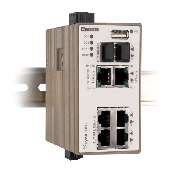
3.3. Hardware Overview Description Description LED indicators SFP transceivers USB connection Power connection I/O connection Ethernet connection RS-232 connection RS-232 and RS-422/485 connection Figure 3. Location of interface ports and LED indicators Description Description I/O connection Console port Accessorie cable, art. no. 1211-2027 Figure 4. -
Page 15: Connector Information
3.4. Connector Information 3.4.1. Ethernet Connection TX Illustration Pin no. Signal Direction Description In/Out Transmitted/Received data In/Out Transmitted/Received data In/Out Transmitted/Received data Not connected Not connected In/Out Transmitted/Received data Not connected Not connected Shield Connected to PE Table 7. Ethernet connection TX 3.4.2. -
Page 16: Rs-232 Connection (Dce)
Guide. An external load in series with an external voltage source is required for proper functionality. For voltage/current, see Interface Specifications. The Digital in is an opto-isolated digital input, which can be used to monitor external events. For voltage/current, see Interface Specifications. External load Status Digital in... -
Page 17: Rs-422/485 Connection
3.4.5. RS-422/485 Connection Illustration Pin no. Signal Direction Description RS-422 (4- RS-485 (2- wire) wire) T+/R+ Out/In RS-422: Transmit RS-485: Transmit/ Receive T-/R- Out/In RS-422: Transmit RS-485: Transmit/ Receive Pin 8 Pin 1 RS-422: Receive Not used Not used RS-422: Receive Not used Not used Table 11. -
Page 18: Connection To The Console Port
3.4.6. Connection to the Console Port The console port can be used to connect to the CLI (Command Line Interface). 1. Connect the serial diagnostic cable to the console port (use only Westermo cable 1211-2027). 2. Connect cable to your computer (USB port, if drivers are needed they can be downloaded from the Westermo web). -
Page 19: Led Indicators
3.5. LED Indicators Status Description Illustration Product has no power GREEN All OK, no alarm condition GREEN Location indicator ("Here I am!"). BLINK Activated when connected to WeConfig tool, or upon request from web or/and CLI. RED BLINK during boot indicates pending cable factory reset. -
Page 20: Sfp Transceivers
Table 14. LED indicators 3.6. SFP Transceivers The product supports UL and IEC certified transceivers only. See Westermo's modular transceivers datasheets 100 Mbit and 1 Gbit for supported SFP transceivers, which can be downloaded from the product support pages at www.westermo.com/support/product-... -
Page 21: Dimensions
3.9. Dimensions Dimensions are stated in mm and are regardless of model. 96 ±1 52 ±1 92 ±1 Figure 8. Dimensional drawing Lynx L108/208-F2G-S2... -
Page 22: Installation
4. Installation 4.1. Mounting This product should be mounted on a 35 mm DIN-rail, which is horizontally mounted inside an apparatus cabinet or similar. It is recommended that the DIN-rail is connected to ground. Snap on the product to the DIN-rail according to the figure. Figure 9. -
Page 23: Cooling
This product runs the Westermo Operating System (WeOS) which provides several management tools that can be used for configuration of the unit. • WeConfig tool This is a custom Westermo tool used for discovery of attached Westermo product. • Web Configuration of the product using the web browser. -
Page 24: Configuration Via A Web Browser
Username: admin Password: westermo Once logged in, use the extensive integrated help function describing all configuration options. Two common task when configuring a new switch is to assign appropriate IP settings, and to change the password of the admin account. - Page 25 NOTE Do not power off the product while the factory reset process is in progress. • Acknowledge that you wish to conduct the factory reset by unplugging the Ethernet cables. The ON LED will stop flashing. This initiates the factory reset process, and after approximately 1 minute the product will restart with factory default settings.
-
Page 26: Specifications
5. Specifications 5.1. Interface Specifications DC, Power port Lx08-F2G-S2-12VDC: Lx08-F2G-S2: Rated voltage 12 - 24 VDC 24 - 48 VDC Operating voltage 9.8 - 36 VDC 19 - 60 VDC Rated current 470 mA (820 mA) at 12 VDC (with 250 mA (380 mA) at 24 VDC 500 mA USB load) (with 500 mA USB load) - Page 27 Ethernet TX Electrical specification IEEE std 802.3 Data rate 10 Mbit/s, 100 Mbit/s, manual or auto Duplex Full or half, manual or auto Circuit type TNV-1 Transmission range Up to 150 m with CAT5e cable or better Isolation All other ports Connection RJ-45, auto MDI/MDI-X Cabling...
- Page 28 RS-422/485 Electrical specification Configurable for EIA RS-232 or EIA RS-422/485 Data rate 50 bit/s - 2 Mbit/s Data format 7 or 8 data bits, odd, even or none parity, 1 or 2 stop bits (2 stop bits only when no parity is set) Circuit type TNV-1 Transmission range...
- Page 29 LVTTL-level (service port, shall not be connected during normal operation. Only to be used during maintenance.) Data rate 115.2 kbit/s Circuit type SELV Data format 8 data bits, no parity, 1 stop bit, no flow control Connection 2.5 mm jack, use only Westermo cable 1211-2027 Lynx L108/208-F2G-S2...
-
Page 30: Type Tests And Environmental Conditions
5.2. Type Tests and Environmental Conditions Environmental Basic Description Test levels phenomena standard EN 61000-4-2 Enclosure Contact: ±6 kV Air: ±8 kV Fast transients EN 61000-4-4 Power port ± 2 kV, direct coupling Earth Ethernet ports ± 2 kV, capacitive coupling clamp Serial ports I/O port Surge... - Page 31 Environmental Basic Description Test levels phenomena standard Compass safe distance IEC 60945 Enclosure Standard compass (5.4°/H deviation) = 15 cm Steering/standby steering / emergency compass (18°/H deviation) = 10 cm Supply voltage surge AREMA Power port 3 x U , 80 ms (72 VDC) Power supply failure DNVGL- Power port...
- Page 32 Environmental Basic Description Test levels phenomena standard Temperatures EN 60068-2-1 Operational -40 to +70°C (-40 to +158°F) EN 60068-2-2 Storage and -50 to +85°C (-58 to +185°F) transport Humidity EN 60068-2-30 Operational 5-95 % relative humidity Storage and transport Altitude Operational 2000 m/80 kPa Service life...
-
Page 33: Revision Notes
3.4.6 Console Port - new missing chapter Rev. N 2020-10 Westermo logo updated, illustrations updated from brown to blue, 2.2 Safety Information updated (text and warnings), 2.3 Care Recommendations updated, old 2.4 Maintenance deleted, 2.5.1 Agency Approvals and Standards Compliance updated, 3.1 Product Description updated, 3.6 SFP Transceivers updated, 3.7 Supported Transceivers... - Page 34 Westermo • Metallverksgatan 6, SE-721 30 Västerås, Sweden Tel +46 16 42 80 00 Fax +46 16 42 80 01 E-mail: info@westermo.com www.westermo.com 6643-2220 REV. T 2023 05 @ Westermo Network Technologies AB, Sweden...
Need help?
Do you have a question about the Lynx L108-F2G-S2 and is the answer not in the manual?
Questions and answers