Westermo Lynx DSS L108-F2G-S2 EX User Manual
Industrial ethernet 8-port device server switch
Hide thumbs
Also See for Lynx DSS L108-F2G-S2 EX:
- User manual (36 pages) ,
- User manual (34 pages) ,
- User manual (21 pages)
Table of Contents
Advertisement
Quick Links
Download this manual
See also:
User Manual
Advertisement
Table of Contents

Related Manuals for Westermo Lynx DSS L108-F2G-S2 EX


Summary of Contents for Westermo Lynx DSS L108-F2G-S2 EX
- Page 1 User Guide 6643-22701 Lynx DSS L108-F2G-S2 EX / L208-F2G-S2 EX WeOS Industrial Ethernet 8-port Device Server Switch www.westermo.com...
-
Page 2: Software Tools
Under no circumstances shall Westermo be responsible for any loss of data or income or any special, incidental, and consequential or indirect damages howsoever caused. -
Page 3: Atex Certification
ATEX certification ATEX certification number Baseefa12ATEX0119X Standards EN 60079-0:2012, EN 60079-15:2010, EN 60079-28:2007 Certification code Ex nA [op is T4] IIC T3 Gc (–40°C ≤ Ta ≤ +70°C) ATEX code II 3G Specific Conditions of Use The equipment must be installed in an area of not more than pollution degree 2 in accordance with IEC/EN 60664-1, and in an enclosure that provides a minimum degree of protection of at least IP54 and complies with the relevant requirements of EN 60079-0 and EN 60079-15. - Page 4 SFP option approved transceivers SFP Transceivers, 100 Mbit 1100-0131 MLC2, Multimode, LC-Connector, 2 km, 1310 nm 1100-0132 SLC20, Singlemode, LC-Connector, 20 km, 1310 nm 1100-0133 SLC40, Singlemode, LC-Connector, 40 km, 1310 nm 1100-0134 SLC80, Singlemode, LC-Connector, 80 km, 1550 nm 1100-0140 SLC120, Singlemode, LC-Connector, 120 km, 1550 nm BiDi Transceivers, 100 Mbit 1100-0145 SLC15-BiDi-A, Singlemode, BiDi, 20 km, 1310 nm TX, 1550 nm RX...
- Page 5 ATEX-Zertifizierung ATEX-Zulassungsnummer Baseefa12ATEX0119X Standards EN 60079-0:2012, EN 60079-15:2010, EN 60079-28:2007 Zertifizierungscode Ex nA [op ist T4] IIC T3 Gc (–40 °C ≤ Ta ≤ +70 °C) ATEX-Code II 3G Spezifische Einsatzbedingungen Die Geräte müssen in einem Bereich welcher einem maximalen Verschmutzungsgrad der Stufe 2 gemäß...
- Page 6 Für SFP-Option zugelassene Transceiver SFP-Transceiver, 100 Mbit 1100-0131 MLC2, Multimode, LC-Anschluss, 2 km, 1310 nm 1100-0132 SLC20, Singlemode, LC-Anschluss, 20 km, 1310 nm 1100-0133 SLC40, Singlemode, LC-Anschluss, 40 km, 1310 nm 1100-0134 SLC80, Singlemode, LC-Anschluss, 80 km, 1550 nm 1100-0140 SLC120, Singlemode, LC-Anschluss, 120 km, 1550 nm BiDi-Transceiver, 100 Mbit 1100-0145 SLC15-BiDi-A, Singlemode, BiDi, 20 km, 1310 nm TX, 1550 nm RX 1100-0146 SLC15-BiDi-B, Singlemode, BiDi, 20 km, 1550 nm TX, 1310 nm RX...
- Page 7 Certification ATEX Numéro de certification ATEX Baseefa12ATEX0119X Normes EN 60079-0:2012, EN 60079-15:2010, EN 60079-28:2007 Code de certification Ex nA [op is T4] IIC T3 Gc (–40°C ≤ Ta ≤ +70°C) Code ATEX II 3G Conditions spéciales d'utilisation L'équipement doit être installé dans une zone où le degré de pollution ne dépasse pas le degré...
- Page 8 Transmetteurs optionnels SFP certifiés Transmetteurs SFP, 100 Mbit 1100-0131 MLC2, multimode, connecteur LC, 2 km, 1310 nm 1100-0132 SLC20, monomode, connecteur LC, 20 km, 1310 nm 1100-0133 SLC40, monomode, connecteur LC, 40 km, 1310 nm 1100-0134 SLC80, monomode, connecteur LC, 80 km, 1550 nm 1100-0140 SLC120, monomode, connecteur LC, 120 km, 1550 nm Transmetteurs Bi-Di, 100 Mbit 1100-0145 SLC15 Bi-Di A, monomode, Bi-Di, 20 km, 1310 nm TX, 1550 nm, RX...
-
Page 9: Maintenance
Maintenance No maintenance is required, as long as the unit is used as intended within the specified conditions. Agency approvals and standards compliance Type Approval / Compliance EN 61000-6-1, Immunity residential environments EN 61000-6-2, Immunity industrial environments EN 61000-6-3, Emission residential environments EN 61000-6-4, Emission industrial environments EN 55022 +A1, Emission IT equipment EN 55024 +A1 + A2, Immunity IT equipment... -
Page 10: Declaration Of Conformity
Declaration of Conformity Westermo Teleindustri AB Declaration of conformity The manufacturer Westermo Teleindustri AB SE-640 40 Stora Sundby, Sweden Herewith declares that the product(s) Type of product Model Ethernet device server switch Lynx DSS L*08-F2G-S2-EX* is in conformity with the following EC directive(s). -
Page 11: Product Description
Product description Status Active Ports 6 x RJ-45, 10/100BaseT. 4 x SFP, 100/1000 Mbit/s. 2 x RJ-45, RS-232/422/485. Description Managed Device Server Switch with routing functionality Warranty period 5 years Approvals Marine DNV Standard for Certification no. 2.4 EMC (Electromagnetic Compatibility) EN 61000-6-1 Immunity residential environments EN 61000-6-2... - Page 12 EN 61000-4-9, 300 A/m pulsed magnetic field EN 61000-4-3, 20 V/m @ (80 – 2700) MHz radiated RF immunity 1 kHz sine, 80% AM EN 61000-4-6, Power port: 10 V, 80% AM, 1 kHz; (0.15 – 80) MHz conducted RF immunity Ethernet: 10 V, 80% AM, 1 kHz;...
- Page 13 Mechanical IEC 60068-2-6, IEC 60068-2-6,(sine), operating vibration 3 – 13.2 Hz: 1mm 13.2 – 100 Hz: 0.7 g 5.5 – 30 Hz: 1.5 g 30 – 50 Hz: 0.42 mm 50 – 500 Hz: 4.2 g IEC 60068-2-64 (random), operating 5 –...
- Page 14 Interface specifications, 100/1000SFP Optical/Electrical specification IEEE std 802.3. 2005 Edition Data rate 100 Mbit/s or 1000 Mbit/s transceivers supported Duplex Full or Auto, depending on transceiver Transmission range Depending on tranceiver Connection SFP slot holding fibre transceiver or copper transceiver Number of ports 1 or 2 Interface specifications, RS-232...
-
Page 15: Sfp Transceivers
Data rate 115.2 kbit/s Data format 8 data bits, no parity, 1 stop bit, no flow control Circuit type SELV Connection 2.5 mm jack, use only Westermo cable 1211-2027 Accessories Description Art no Westermo console cable 1211-2027 RJ45 to terminal block... -
Page 16: Safety Control Drawing
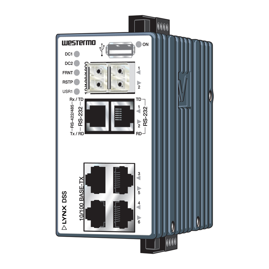
Safety control drawing Location of interface ports and LED’s LED Indicators (for details see page 16) Power connection (for details see page 9 and 15) Position Direction* / description Output values Out / VBUS In/out / D– = 5 VDC max In/out / D+ = 500 mA max Shield... - Page 17 RS-422/485 (for more details see below) Signal Position Direction Description Input/Output values RS-422 RS-485 (4-wire) (2-wire) No. 1 T+/R+ Out/In RS-422: Transmit RS-485: Transmit/Receive No. 2 T– T–/R– Out/In RS-422: Transmit RS-485: Transmit/Receive U = 5 V max No. 3 R–...
-
Page 18: Connection To Console Port
The following steps needs to be taken 1. Connect the serial diagnostic cable to the console port (use only Westermo cable 1211-2027). 2. Connect cable to your computer (USB port, if drivers are needed they can be downloaded from our Web page). -
Page 19: Power Connection
Safety control drawing Power connection Product 4-position Direction Description Input values marking No. 1 +DC1 Input Supply voltage input DC1 = (19 – 60) VDC No. 2 +DC2 Input Supply voltage input DC2 = 380 mA @ 24 VDC No. 3 -COM Input Common... -
Page 20: Led Indicators
LED indicators Status Description Unit has no power. GREEN All OK, no alarm condition. Alarm condition, or until unit has started up. (Alarm conditions are configurable, see ''WeOS Management Guide''). BLINK Location indicator ("Here I am!"). Activated when connected to IPConfig Tool, or upon request from Web or CLI. - Page 21 Mounting This unit should be mounted on 35 mm DIN-rail, which is horizontally mounted inside an apparatus cabinet or similar. It is recommended that the DIN-rail is connected to ground. Snap on mounting, see figure. Mounting Lynx with integrated DIN-clip: Removal Removing Lynx with integrated DIN-clip: Press down the support at the back of the unit using a screwdriver.
-
Page 22: Getting Started
• IPConfig tool This is a custom Westermo tool used for discovery of attached Westermo units. Note! Version of IP Config tool must be 10.4.0 or higher. • Web Configuration of the unit using the web browser. -
Page 23: Referring Documents
Referring documents Type Description Document number Management Guide Westermo OS management guide 6101-3201 Factory default on L108-F2G-S2 EX / L208-F2G-S2 EX It is possible to set the unit to factory default settings by using two straight standard Ethernet RJ-45 cables. -
Page 24: Sales Units
Other Offices infos@westermo.fr sales@westermo.com.sg www.westermo.fr www.westermo.com Germany Sweden info@westermo.de info.sverige@westermo.se www.westermo.de www.westermo.se For complete contact information, please visit our website at www.westermo.com/contact or scan the QR code REV.B 6643-22701 2015-01 Westermo Teleindustri AB, Sweden – A Beijer Electronics Group Company...
Need help?
Do you have a question about the Lynx DSS L108-F2G-S2 EX and is the answer not in the manual?
Questions and answers