
Related Manuals for Westermo Lynx L105-S1


Summary of Contents for Westermo Lynx L105-S1
- Page 1 Lynx L105-S1 and L205-S1 Industrial Ethernet 5-Port Device Server Switch...
-
Page 2: Table Of Contents
4.4. Getting Started ..............17 4.5. Configuration Via a Web Browser ..........18 4.6. Factory Default ..............18 5. Specifications ................20 5.1. Interface Specifications ............20 5.2. Type Tests and Environmental Conditions ......... 23 6. Revision Notes ................25 Lynx L105-S1 and L205-S1... -
Page 3: General Information
Westermo reserves the right to revise this document or withdraw it at any time without prior notice. Under no circumstances shall Westermo be responsible for any loss of data or income or any special, incidental, and consequential or indirect damages howsoever caused. -
Page 4: Safety And Regulations
No personal injury Minor damage to the to avoid misuse of the product product, confusion or misunderstanding NOTICE Used for highlighting general, No personal injury Minor damage to the but important information product NOTE Table 1. Warning levels Lynx L105-S1 and L205-S1... -
Page 5: Safety Information
WARNING - PROTECTIVE FUSE It must be possible to disconnect manually from the power supply. Ensure compliance to national installation regulations. Replacing the internal fuse must only be performed by Westermo qualified personell. WARNING - POWER SUPPLY CONNECTION There are safety regulations on which power sources that shall be used in conjunction with the product. - Page 6 Temperature Limit according to the product's relevant electrical safety standard. CAUTION - CABLE TEMPERATURE RATING FOR FIELD TERMINAL WIRES There may be a requirement on the minimum temperature rating of the cable to be connected to the field wiring terminals, see Interface Specifications. Lynx L105-S1 and L205-S1...
-
Page 7: Care Recommendations
If the product is used in a manner not according to specification, the protection provided by the equipment may be impaired. If the product is not working properly, contact the place of purchase, nearest Westermo distributor office or Westermo technical support. -
Page 8: Fcc Part 15.105 Class B Notice
2.5.4. Simplified Declaration of Conformity Hereby, Westermo declares that this product is in compliance with applicable EU directives. The full EU declaration of conformity and other detailed information is available at www.westermo.com/support/product-support. -
Page 9: Product Description
-40 to +70°C (-40 to +158°F) can be achieved with no moving parts or cooling holes in the case. The Lynx series has been tested both by Westermo and external test institutes to meet many EMC, isolation, vibration and shock standards, all to the highest levels suitable for heavy industrial environments and rail trackside applications. -
Page 10: Hardware Overview
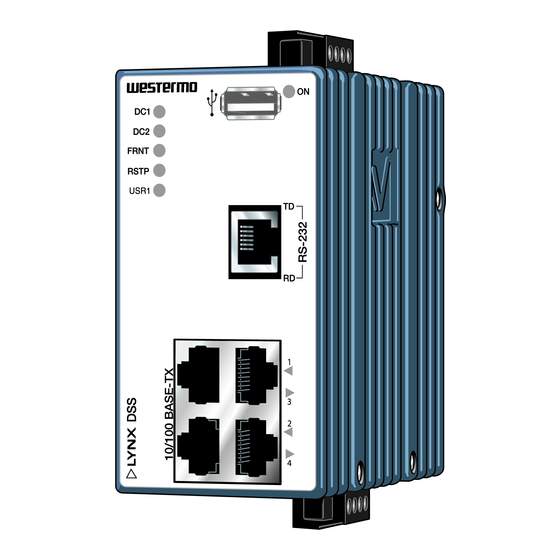
Power connection I/O connection Ethernet connection RS-232 connection Figure 3. Location of interface ports and LED indicators Description Description I/O connection Console port Accessorie cable, art. no. 1211-2027 Figure 4. Location of interface ports, bottom view Lynx L105-S1 and L205-S1... -
Page 11: Connector Information
Product marking Direction Description Status + Output Alarm relay (status) contact Status - Output Alarm relay (status) contact Digital in + Input Digital in + Digital in - Input Digital in - Table 5. I/O connection Lynx L105-S1 and L205-S1... -
Page 12: Rs-232 Connection (Dce)
Pin no. Signal Direction Description Data Set Ready Data Carrier Detect Data Terminal Ready Signal Ground, not chassis ground Receive Data Pin 8 Pin 1 Transmit Data Clear To Send Request To Send Table 6. RS-232 connection Lynx L105-S1 and L205-S1... -
Page 13: Usb Connection
3.4.5. USB Connection Illustration Direction Description VBUS In/Out In/Out In/Out Connected to protective earth Table 7. USB connection Lynx L105-S1 and L205-S1... -
Page 14: Led Indicators
Port alarm and no link. Or if FRNT or RSTP mode, port is blocked. Supply voltage levels must be ensured externally. A green LED indicator may not guarantee a valid operating voltage level Table 8. LED indicators Lynx L105-S1 and L205-S1... -
Page 15: Dimensions
3.6. Dimensions Dimensions are stated in mm and are regardless of Lynx model. 96 ±1 52 ±1 92 ±1 Figure 6. Dimensional drawing Lynx L105-S1 and L205-S1... -
Page 16: Installation
Figure 7. Mounting of product 4.2. Removal of Product This product has an integrated DIN-clip. To remove the product, press down the support at the back with a screwdriver and lift it off the DIN-rail. Figure 8. Removal of product Lynx L105-S1 and L205-S1... -
Page 17: Cooling
This product runs the Westermo Operating System (WeOS) which provides several management tools that can be used for configuration of the unit. • WeConfig tool This is a custom Westermo tool used for discovery of attached Westermo product. • Web Configuration of the product using the web browser. -
Page 18: Configuration Via A Web Browser
To go ahead with factory reset: NOTE Do not power off the product while the factory reset process is in progress. Lynx L105-S1 and L205-S1... - Page 19 • To skip the factory reset process, just wait for approximately 30 seconds (after the ON LED starts flashing RED) without unplugging the Ethernet cables. The product will conduct a normal boot with the existing settings. Lynx L105-S1 and L205-S1...
-
Page 20: Specifications
Full or half, manual or auto Circuit type TNV-1 Transmission range Up to 150 m with CAT5e cable or better Isolation All other ports Connection RJ-45, auto MDI/MDI-X Cabling Shielded CAT5e or better is recommended Conductive chassis Number of ports Lynx L105-S1 and L205-S1... - Page 21 To all other ports Connector Detachable screw terminal Conductor cross section 0.14 - 1.5 mm² (AWG 28 - 16) Stripping length cable 7 mm Tightening torque, terminal 0.22 - 0.25 Nm screw Tightening torque, screw 0.3 Nm flange Lynx L105-S1 and L205-S1...
- Page 22 USB receptable connector type A Console port Electrical specification LVTTL/LVCMOS-level Data rate 115.2 kbit/s Circuit type SELV Data format 8 data bits, no parity, 1 stop bit, no flow control Connection 2.5 mm jack, use only Westermo cable 1211-2027 Lynx L105-S1 and L205-S1...
-
Page 23: Type Tests And Environmental Conditions
CISPR 16-2-1 Power port Class B/DNV bridge ANSI C63,4 Ethernet Class B (FCC Part 15b) Dielectric strength EN 60950-1 Power port to all 1.5 kVrms, 50 Hz, 1 min other ports Ethernet ports to all other ports Lynx L105-S1 and L205-S1... - Page 24 0.7 kg Degree of protection EN 60529 Enclosure IP40 Cooling Convection Refer to "Safety and Regulations" chapter regarding touch temperature Might require Ethernet cables to be fastened close to the unit. Table 10. Environmental and mechanical conditions Lynx L105-S1 and L205-S1...
-
Page 25: Revision Notes
Change description Rev. I 2020-10 Westermo logo updated, illustrations updated from brown to blue, new information structure throughout the manual, 1.2 About This Guide - new chapter, 2 Safety and Regulations - entire chapter updated, 3.1. Product Description updated, 3.2. Available Models - new chapter, 3.6 Dimensions - new chapter, 4.1 Mounting updated, 4.2 Removal of Product updated... - Page 26 Lynx L105-S1 and L205-S1...
- Page 27 Lynx L105-S1 and L205-S1...
- Page 28 Westermo • SE-635 35 Stora Sundby, Sweden Tel +46 16 42 80 00 Fax +46 16 42 80 01 E-mail: info@westermo.com www.westermo.com 6643-2230 REV. I 2020 10 Westermo Network Technologies AB, Sweden...
Need help?
Do you have a question about the Lynx L105-S1 and is the answer not in the manual?
Questions and answers