Sign In
Upload
Download
Table of Contents
Contents
Add to my manuals
Delete from my manuals
Share
URL of this page:
HTML Link:
Bookmark this page
Add
Manual will be automatically added to "My Manuals"
Print this page
×
Bookmark added
×
Added to my manuals
Manuals
Brands
Westermo Manuals
Switch
Lynx DSS L206-S2
User manual
Westermo Lynx DSS L206-S2 User Manual
Industrial ethernet 6-port device server switch
Hide thumbs
Also See for Lynx DSS L206-S2
:
User manual
(21 pages)
1
2
3
4
5
6
7
8
9
10
11
12
13
14
15
16
17
18
19
20
21
22
23
24
Table Of Contents
25
page
of
25
Go
/
25
Contents
Table of Contents
Bookmarks
Table of Contents
General Information
Before Installation
Warning - Hazardous Voltage
Product Disposal
Care Recommendations
Simplified EU Declaration of Conformity
Agency Approvals and Standards Compliance
Type Tests and Environmental Conditions
Interface Specifications
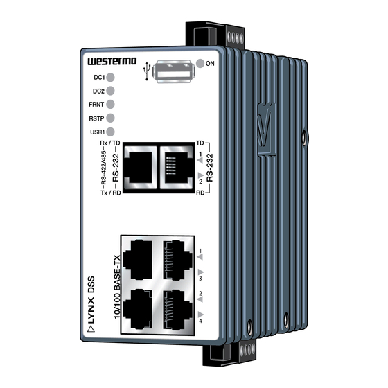
Location of Interface Ports and Leds
Connection to Console Port
Power Connection
Led Indicators
Getting Started
Referring Documents
Document Number
Advertisement
Quick Links
Download this manual
www.westermo.com
Lynx DSS
L106-S2/L206-S2
Industrial Ethernet
6-port Device Server Switch
WeOS
Table of
Contents
Previous
Page
Next
Page
1
2
3
4
5
Advertisement
Table of Contents
Need help?
Do you have a question about the Lynx DSS L206-S2 and is the answer not in the manual?
Ask a question
Questions and answers
Related Manuals for Westermo Lynx DSS L206-S2
Network Router Westermo Lynx DSS User Manual
Industrial ethernet 5-port device server switch (21 pages)
Switch Westermo Lynx DSS L108 User Manual
Industrial ethernet 8-port device server switch (21 pages)
Switch Westermo Lynx DSS L108-F2G-S2 EX User Manual
Industrial ethernet 8-port device server switch (25 pages)
Switch Westermo Lynx DSS L106-S2 User Manual
Industrial ethernet 6-port device server switch (25 pages)
Switch Westermo Lynx DSS L206-S2-EX User Manual
Industrial ethernet 6-port device server switch (28 pages)
Switch Westermo Lynx DSS L206-F2G EX User Manual
Industrial ethernet 6-port switch (28 pages)
Switch Westermo Lynx L108-F2G-S2 User Manual
Industrial ethernet 8-port device server switch (36 pages)
Switch Westermo Lynx L108-F2G-S2 User Manual
Industrial ethernet 8-port device server switch (34 pages)
Switch Westermo Lynx L106-S2 User Manual
Industrial ethernet 6-port device server switch (28 pages)
Switch Westermo Lynx DSS L106-F2G EX User Manual
Industrial ethernet 6-port switch (28 pages)
Switch Westermo Lynx 3000 Series User Manual
Industrial ethernet switch (32 pages)
Switch Westermo Lynx L108-F2G-S2 User Manual
Industrial ethernet 8-port device server switch (32 pages)
Switch Westermo Lynx 3000 Series User Manual
Industrial gigabit switch (32 pages)
Switch Westermo Lynx L206-F2G EX User Manual
Industrial ethernet 6-port switch (25 pages)
Switch Westermo Lynx DSS L205-S1-EX User Manual
Industrial ethernet 5-port device server switch (26 pages)
Switch Westermo Lynx L206-F2G-EX User Manual
Industrial ethernet 6-port switch (29 pages)
This manual is also suitable for:
Lynx dss l106-s2
Table of Contents
Print
Rename the bookmark
Delete bookmark?
Delete from my manuals?
Login
Sign In
OR
Sign in with Facebook
Sign in with Google
Upload manual
Upload from disk
Upload from URL


Need help?
Do you have a question about the Lynx DSS L206-S2 and is the answer not in the manual?
Questions and answers