Table of Contents
Advertisement
Quick Links
Advertisement
Table of Contents

Related Manuals for Westermo Lynx Plus


Summary of Contents for Westermo Lynx Plus
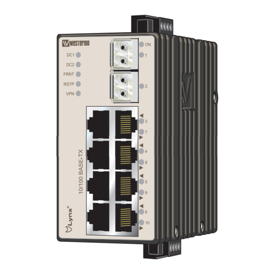
- Page 1 User Guide 6643-2210 Lynx+ Industrial Ethernet 10-port Switch www.westermo.com...
-
Page 2: License Information
Under no circumstances shall Westermo be responsible for any loss of data or income or any special, incidental, and consequential or indirect damages howsoever caused. - Page 3 Do not use or store the unit in dusty, dirty areas, connectors as well as other mechanical part may be damaged. If the unit is not working properly, contact the place of purchase, nearest Westermo distributor office or Westermo Tech support.
-
Page 4: Maintenance
Note. Fibre Optic Handling Fibre optic equipment needs special treatment. It is very sensitive to dust and dirt. If the fibre will be disconnected from the unit the protective hood on the transmitter/receiver must be connected. The protective hood must be kept on during transportation. The fibre optic cable must also be handled the same way. -
Page 5: Declaration Of Conformity
Declaration of Conformity Westermo Teleindustri AB Declaration of conformity The manufacturer Westermo Teleindustri AB SE-640 40 Stora Sundby, Sweden Type of product Model Art no Ethernet switch L+210-series switches 3643-0100 is in conformity with the following EC directive(s). Short name... -
Page 6: Type Tests And Environmental Conditions
Type tests and environmental conditions Environmental phenomena Basic standard Description Test levels EN 61000-4-2 Enclosure Contact: ±6 kV Air: ±8 kV Fast transients EN 61000-4-4 Power port ±2 kV Signal ports ±2 kV Earth port ±1 kV L-E: ±0.5 kV, 12 Ω, 9 μF Surge EN 61000-4-5 Power port... - Page 7 Description Lynx+ is an Industrial switch made for harsh enviroments. The switch can be used in ether 100 Mbit or Gigabit networks due to our multi-rate SFP solution. Lynx+ can also be used together with our previous Lynx-series of switches. Our unique FRNT (Fast Recovery of Network Topology) technology is the fastest protocol on the market to re-configure a network in the event of any link or hardware failure.
-
Page 8: Interface Specifications
Interface specifications Power Operating voltage Rated: 24 to 48 VDC Operating: 19 to 60 VDC Rated current 240 mA @ 24 VDC 120 mA @ 48 VDC Rated frequency Inrush current, I 6.4 · 10 s @ 48 VDC Startup current* 2 * Rated current Polarity Reverse polarity protected... -
Page 9: Sfp Transceivers
8 data bits, no parity, 1 stop bit, no flow control Circuit type SELV Isolation to All other Connection 2.5 mm jack, use only Westermo cable 1211-2027 SFP Transceivers Supported transceivers See SFP Transceivers User Guide 6100-0000 for supported SFP transceivers. Note: The unit supports Westermo labelled transceivers only. Deviations With copper transceiver 1100-0148 the specified operating temperature on Lynx+ is 0 to +50ºC. - Page 10 The following steps needs to be taken 1. Connect the serial diagnostic cable to the console port (use only Westermo cable 1211-2027). 2. Connect cable to your computer (USB port, if drivers are needed they can be downloaded from our Web page).
-
Page 11: Power Connection
Power connection 4-position Product marking Direction Description No. 1 +DC1 Input Supply voltage input DC1 No. 2 +DC2 Input Supply voltage input DC2 No. 3 -COM Input Common No. 4 -COM Input Common Lynx+ supports redundant power connection. The positive inputs are +DC1 and +DC2, the negative input for both supplies are –COM. -
Page 12: Led Indicators
LED indicators Status Description Unit has no power. GREEN All OK, no alarm condition. Alarm condition, or until unit has started up. (Alarm conditions are configurable, see ''WeOS Management Guide''). BLINK Location indicator ("Here I am!"). Activated when connected to IPConfig Tool, or upon request from Web or CLI. - Page 13 Mounting This unit should be mounted on 35 mm DIN-rail, which is horizontally mounted inside an apparatus cabinet or similar. Snap on mounting, see figure. Mounting Lynx with integrated DIN-clip: Removal Removing Lynx with integrated DIN-clip: Press down the support at the back of the unit using a screwdriver. See figure. Cooling This unit uses convection cooling.
-
Page 14: Getting Started
This product runs Westermo Operating System (WeOS) which provides several management tools that can be used for configuration of the unit. • IPConfig tool This is a custom Westermo tool used for discovery of attached Westermo units. • Web Configuration of the unit using the web browser. -
Page 15: Referring Documents
Referring documents Type Description Document number Management Guide Westermo OS management guide 6101-3201 Factory default on Lynx It is possible to set the unit to factory default settings by using two standard Ethernet RJ-45 cables. 1. Power off the switch and disconnect all Ethernet cables (copper and fibre). - Page 16 Phone +65 6743 9801 • Fax +65 6745 0670 E-Mail: sales@westermo.co.uk E-Mail: sales@westermo.com.sg Westermo Data Communications GmbH Goethestraße 67, 68753 Waghäusel Tel.: +49(0)7254-95400-0 • Fax.:+49(0)7254-95400-9 E-Mail: info@westermo.de Westermo Teleindustri AB have distributors in several countries, contact us for further information.
Need help?
Do you have a question about the Lynx Plus and is the answer not in the manual?
Questions and answers