SureCall Force-5 User Manual
Five-band wireless adjustable signal booster / kit
Hide thumbs
Also See for Force-5:
- User manual (12 pages) ,
- User manual (16 pages) ,
- User manual (24 pages)

Related Manuals for SureCall Force-5


Summary of Contents for SureCall Force-5
-
Page 1: Table Of Contents
PERATION -5 P ORCE ACKAGES -5 B ORCE OOSTER ARDWARE INSTALLATION ELECTION NSTALLATION NSTRUCTIONS UTOMATIC HUTDOWN TROUBLESHOOTING FREQUENTLY ASKED QUESTIONS 16 OBTAINING TECHNICAL SUPPORT 16 WARRANTY Force-5™ Booster, Force-5 SPECIFICATIONS Omni Kit, Force-5 Panel Kits (FORCE-5) SAFETY INFORMATION User Guide... -
Page 2: Introduction
This guide contains all the information you need to get your SureCall Force-5 booster system up and running. Theory of Operation... -
Page 3: Surecall Force-5 Packages
2.53dB 2.63dB 3.57dB 3.36 dB\3.77 dB 40 feet or (40 feet) longer * All equivalent antennas and cables are suitable for use with the Force-5 booster. Table 2. Dual Indoor Antenna Kit Component Product Number (Description) Quantity Notes Outdoor Antennas*... -
Page 4: Power Supply
Indoor Antenna* CM248W 4 pcs * All equivalent antennas and cables are suitable for use with the Force-5 booster. Note: Multiple indoor antenna kit is also an option. Note: For the signal booster to work, the following items are required:... -
Page 5: Force-5 Booster Hardware
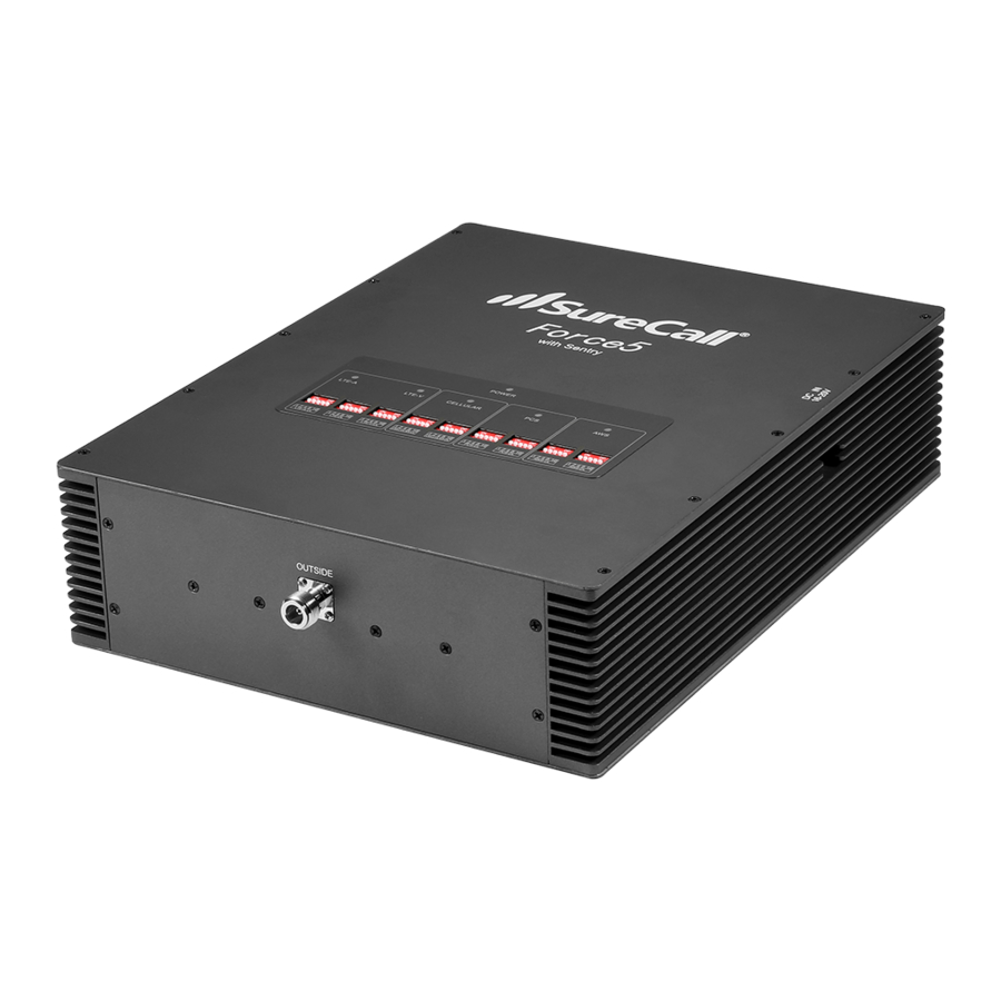
INTRODUCTION Force-5 Booster Hardware The following figure shows the key hardware components on the SureCall Force-5 cellular signal booster. Refer to this figure as you install your SureCall Force-5 components. Outside Antenna Connector Power LED (not shown) Four Banks of DIP Switches (left to right): •... -
Page 6: Installation
Although cell phone providers try to place towers for maximum coverage, local ordinances and terrain features can restrict tower locations, which can limit signal strength at your location. SureCall Force-5 Cellphone-Mate, Inc. Page 6 All rights reserved. -
Page 7: Installation Instructions
Step 2. Connect the Inside Antenna Mount the inside antenna: x Omnidirectional dome antenna: mount the antenna on the ceiling in a central location where you want reception. x Panel antenna: install the antenna SureCall Force-5 Cellphone-Mate, Inc. Page 7 All rights reserved. - Page 8 Using the CM400 cable, connect the inside antenna to the booster connector marked INSIDE (see page 5). Hand tighten the connection. SureCall Force-5 Cellphone-Mate, Inc. Page 8 All rights reserved.
- Page 9 (see page 5). The booster is rated for 5-20V input voltage. DO NOT use the booster with a higher voltage power supply. This can damage the booster and/or cause personal injury. SureCall Force-5 Cellphone-Mate, Inc. Page 9 All rights reserved.
- Page 10 Moving a switch down (away from the LEDs) turns OFF the switch and increases booster gain for the selected channel. x Moving a switch up (toward the LEDs) turns ON the switch and decreases booster gain for the selected channel. SureCall Force-5 Cellphone-Mate, Inc. Page 10 All rights reserved.
- Page 11 3 dB 7 dB 15 dB 21 dB 31 dB Tip: The Force-5 signal booster comes unattenuated or fully powered. If you cannot obtain sufficient antenna separation, use the DIP switches to attenuate the booster’s dB gain. SureCall Force-5 Cellphone-Mate, Inc.
-
Page 12: Leds
Green ON or blink = booster is receiving power. OFF = booster is not receiving power. Red ON = oscillation has occurred for longer than 15 minutes and the booster is shutting down (see Automatic Shutdown on page 13). SureCall Force-5 Cellphone-Mate, Inc. Page 12 All rights reserved. -
Page 13: Automatic Shutdown
INSTALLATION Automatic Shutdown SureCall boosters that have automatic shutdown work in the following way: The cellular LEDs are usually the first side to experience oscillation. When oscillation is detected in the uplink and/or downlink, the appropriate red Warning LEDs flash and Power turns red. -
Page 14: Troubleshooting
Check the green POWER LED on the booster. If it is OFF, return the power supply to Cellphone-Mate. Contact tech support at 1-888-365-6283, email support@surecall.com, or go to surecall.com and log on via online support to receive a Return Merchandise Authorization (RMA). - Page 15 TROUBLESHOOTING Problem Resolution Your booster restarted Each SureCall booster is equipped with Auto Shutdown and shut down for 15 to prevent cell tower interference. The outside antenna minutes, and is now shut may be close to a cell tower. Move the outside antenna to down permanently.
-
Page 16: Frequently Asked Questions
FREQUENTLY ASKED QUESTIONS Frequently Asked Questions For a list of Frequently Asked Questions and a comprehensive, up-to-date Troubleshooting Guide, please visit our website at: www.surecall.com or call us at 1-800-365-6283. Obtaining Technical Support You can also consult a Cellphone-Mate technical specialist directly by emailing us at support@surecall.com... -
Page 17: Warranty
Cellphone-Mate. This warranty shall not apply to any products or parts thereof which have been subject to accident, negligence, alteration, abuse, or misuse. Cellphone-Mate makes no warranty whatsoever in respect to accessories or parts not supplied by it. SureCall Force-5 Cellphone-Mate, Inc. Page 17... - Page 18 If one or more provisions provided herein are held to be invalid or unenforceable under applicable law, then such provision shall be ineffective and excluded to the extent of such invalidity or unenforceability without affecting in any way the remaining provisions hereof. SureCall Force-5 Cellphone-Mate, Inc. Page 18...
-
Page 19: Specifications
RF Connectors: N Female, both ends Power Consumption: <50W Dimensions: 11.3 x 10.9 x 3.5 in. (28.6 x 27.6 x 8.84 cm.) Weight: 16.5 lbs. (7.48 kgs.) FCC ID (USA): RSNFORCE–5 SureCall Force-5 Cellphone-Mate, Inc. Page 19 All rights reserved. -
Page 20: Safety Information
Increase the separation between the equipment and receiver. Connect the equipment into an outlet on a circuit different from that to which the receiver is connected. Consult the dealer or an experienced radio/TV technician for help. SureCall Force-5 Cellphone-Mate, Inc. Page 20 All rights reserved. - Page 21 Copyright © 2014. All Rights Reserved. All trademarks and registered trademarks are the property of their respective owners. Force-5 User Guide February 10, 2014 (20130228) V1.3?? SureCall Force-5 Cellphone-Mate, Inc.
Need help?
Do you have a question about the Force-5 and is the answer not in the manual?
Questions and answers