Table of Contents
Advertisement
Advertisement
Table of Contents

Subscribe to Our Youtube Channel
Related Manuals for SportsArt Fitness T621


Summary of Contents for SportsArt Fitness T621
- Page 1 T621 Repair Manual (Electronics)
-
Page 2: Table Of Contents
3-3-1. Troubleshooting-Key Malfunction(Display)-T621 3-3-2. Troubleshooting-Key Malfunction-T621 3-4-1. Troubleshooting-Telemetry Heart Rate Malfunction-T621 3-5-1. Troubleshooting-Contact (HTR) Heart Rate Malfunction-T621 3-6-1. Troubleshooting-The Fuse Breaks at Start-T621 3-6-2. Troubleshooting-The Fuse Breaks at Motor Start-T621 3-6-3. Troubleshooting-The Fuse Breaks during Use-T621 3-7-1. Troubleshooting-ERR-1 T621 3-8-1. Troubleshooting-ERR-3 T621 3-9-1. - Page 3 3-13-1. Other Information-Error Messages-T621 Inspecting and Testing-Transformer Test – T621 4-1-1. Inspecting and Testing-Motor Carbon brush – T621 4-2-1. Inspecting and Testing-wheel, speed sensor – T621 4-3-1. Inspecting and Testing-Motor voltage – T621 4-4-1. 4-5-1. Inspecting and Testing-Motor Thermal Sensor Test-T621 4-6-1.
-
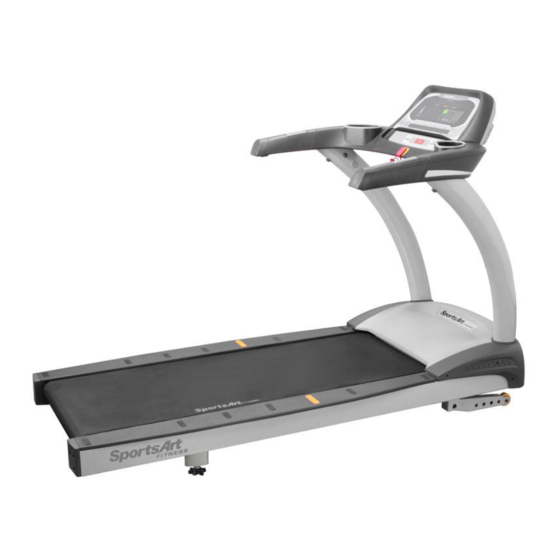
Page 4: Product Picture-T621
1-1. Product Picture-T621 1-1-1... -
Page 5: Display-T621
1-2. Display-T621 1-2-1... -
Page 6: Component Placement-T621 Display
1-3. Component Placement-T621 Display Telemetry heart rate receiver board Display board 1-3-1... - Page 7 1-3. Component Placement-T621 Display HTR board Bridge board Safety key board Soft keys 1-3-2...
-
Page 8: Component Placement-T621 Drive Board Area
1-3. Component Placement –T621 Drive Board Area Speed sensor Temperature sensor Drive board DC motor AC incline motor Filter Transformer 1-3-3... -
Page 9: Block Diagram-T621
1-4. Block Diagram-T621 Display board Polar board Safety key Bridge Keypad board Sensor L HTR board Sensor R Motor FUSE Filter Drive board Speed sensor Transformer Temperature sensor Incline motor Zero switch 1-4-1... -
Page 10: Connections-T621 Display Board
1-5. Connections-T621 Display Board To telemetry HR To bridge board (HTR) To drive board To bridge board (safety key) To bridge board (fan) To bridge board (keypad) To drive board To bridge board 1-5-1... -
Page 11: Connections-T621 Bridge Board
1-5. Connections-T621 Bridge Board To display To HTR board To safety key board 1-5-2... -
Page 12: Connections-T621 Drive Board
1-5. Connections-T621 Drive Board To incline motor To filter To display To speed sensor To motor temperature sensor To motor To incline zero switch 1-5-3... -
Page 13: Indicator Leds-T621 Display Board
1-6. Indicator LEDs-T621 Display Board Power indicator Lit indicates display has power. HR indicator 1-6-1... -
Page 14: Indicator Leds-T621 Drive Board
1-6. Indicator LEDs-T621 Drive Board LED4 CUS_UP Indicator LED11 I_SENSE Indicator Lit = Cushion motor is extended (firm). Lit = High current protective function is activated. LED7 DN Indicator Transformer fuse LED3 CUS_DN Indicator Lit = Incline is operating down. -
Page 15: Display Specifications-T621
1-7. Display Specifications-T621 Details Notes Specification 110V / 220V Exterior power supply DC motor (with internal thermal switch) Motor Has brushes Has heat protection Infrared optic sensor Speed sensor KPH: 0.2 - 20.0(KPH) Speed Range MPH: 0.1 –12.0(MPH) Power: AC motor (110V or 220V) -
Page 16: Electronics Troubleshooting Chart-T621
2-1. Electronics Troubleshooting Chart-T621 Malfunction Circumstance Inspection and test points Components to Notes replace Safety key Put safety key in place. 1. Inspect the cable connections on the lower part of the Safety key board malfunction Display has no reaction. - Page 17 Soft key Press soft key, display no rebound, 1. Replace the display soft key. Soft key malfunction (display) (display) Soft key Key does not operate, 1. Inspect the bridge board soft key connection. Soft key malfunction or operates continually. 2. Replace the soft key. ERR 1 Motor does not rotate, ERR1 1.
- Page 18 KPH/MPH setting Press the <CHANGE> key three seconds; the display will show “UNIT-MPH” or “UNIT-KPH”. Press INCLINE<▲>/<▼> to select KPH or MPH. Press <ENTER> to confirm your choice. FOR ACCURATE HR , FOR ACCURATE HR , 1. Hold contact heart rate grips firmly to test the HOLD SENSORS HOLD SENSORS FIRMLY HTR function.
- Page 19 Troubleshooting Model: T621 Malfunction: Safety key malfunction Circumstance: Put the safety key in place. The display does not operate. Display shows “safety key”. Possible cause: Safety key board malfunction Troubleshooting: 1. Inspect the safety key magnet. 2. Inspect the bridge board cable connections.
- Page 20 Troubleshooting Model: T621 Malfunction: Unit does not operate Circumstance: Turn on unit power; the power indicator does not light. Possible cause: Inadequate incoming power supply or component malfunction. Troubleshooting: 1. Inspect the power cable connection. 2. Inspect cable connections under the motor cover.
- Page 21 Troubleshooting Model: T621 Malfunction: No start up. Unit does not operate. Circumstance of malfunction: Turn unit power on; the power indicator LED does not light. Possible causes: 1. Transformer problem. 2. Cables are not connected properly, or the drive board is malfunctioning.
- Page 22 Troubleshooting Model: T621 Malfunction: Key malfunction – display Circumstance of malfunction: Press display keys; The display shows no reaction. Or keys operate continually. Possible cause: 1. Wires to the display board are not connected properly. Soft key connection 2. Soft keys are bad.
- Page 23 Troubleshooting Model: T621 Malfunction: Key malfunction – soft key Circumstance: Press the display key; the display shows no reaction, or keys operate continually. Possible cause: 1. Soft key malfunction 2. The bridge board soft key connections are not connected properly.
- Page 24 Troubleshooting Model: T621 Malfunction: No heart rate reading appears. Circumstance: No heart rate reading appears. Possible causes: 1. Heart rate transmitter battery power is insufficient. 2. Heart rate receiver is bad. 3. Environmental noise, such as lights or speakers, interferes with reception.
- Page 25 Troubleshooting Model: T621 Name Function HTR Indicators Malfunction: Contact (Heart Touch Rate) malfunction LED1 POLAR LED Flashing indicates incoming Circumstance: Place hands on heart rate contact telemetry signal. sensors. Heart rate values appear to be LED2 HTR contact LED Lit indicates user is gripping HTR inaccurate.
- Page 26 Troubleshooting Model: T621 Malfunction: The fuse breaks. Circumstance: Turn on unit. The fuse immediately blows. Possible cause: 1. Components and the frame have an abnormal electrical short. 2. Drive board component malfunction. Troubleshooting: 1. Inspect the power cord. Is the cord insulation broken and creating an electrical short? 2.
- Page 27 Troubleshooting Model: T621 Malfunction: The fuse has broken. Circumstance: 1. Press the speed up key. The motor rotates. Then the fuse blows. Possible cause: 1. Motor windings have an electrical short. 2. Drive board malfunction. Troubleshooting: 1. Replace the drive board as a test.
- Page 28 Troubleshooting Model: T621 Malfunction: The fuse has blown. Circumstance: After a period of use, the fuse suddenly breaks. Possible cause: 1. Fuse holder malfunction 2. Deck or belt wear 3. Drive board malfunction Troubleshooting: 1. Inspect the fuse and fuse holder installation.
- Page 29 Troubleshooting Model: T621 Malfunction: Error 1 Circumstance: Press the speed key. Speed engages. Before the motor rotates, Error 1 appears. Possible cause: 1. Motor does not rotate. Drive board or motor malfunctions. Troubleshooting: 1. Inspect all cable connections. 2. Inspect the display board IC connection.
- Page 30 Troubleshooting Model: T621 Malfunction: ERR1 Circumstance: Press the speed up key. Motor rotates. ERR1 appears. Possible cause: 1. Motor rotatesoptic sensor malfunctions Troubleshooting: 1. Inspect all cable connections. 2. Inspect whether the LED6 indicator on drive board flashes. If not, the optic sensor is malfunctioning. Either clean the optic sensor sensor head or replace the optic sensor.
- Page 31 Troubleshooting Model: T621 Malfunction: ERR3 Circumstance: Display speed and actual speed differ. Possible cause: 1. Optic wheel teeth or optic sensor malfunction 2. Drive board malfunction Troubleshooting: 1. Inspect whether optic wheel teeth are missing. 2. Replace the optic sensor as a test.
- Page 32 Troubleshooting Model: T621 Malfunction: ERR7 Circumstance: The incline never recalibrated; ERR7 appeared. Possible cause: 1. Incline does not operate up or down and calibrate. 2. Drive board is malfunctioning. Troubleshooting: 1. Inspect whether incline UP or DN LEDs light during operation.
- Page 33 Troubleshooting Model: T621 Malfunction: The message “SERVICE REQUIRED TREADMILL SHUTTING DOWN STOPPING” appears. Possible cause: 1. The excessive heat protective function is activated. Troubleshooting: 1. This message indicates that the motor is overheating. Please turn off the unit and allow it to rest for one hour.
- Page 34 Other Instructions Model: T621 Item: Set KPH/MPH units and view total distance and time. Method: 1. Press and hold the <CHANGE> key for three seconds to enter the user setting mode. 2. The display will show “UNIT-MPH” (imperial) or “UNIT-KPH” (metric) units.
- Page 35 Other Instructions Model: T621 Malfunction: SERVICE NEEDED-APPLY LUBE Circumstance: The message “SERVICE NEEDED-APPLY LUBE” appears, and the unit stops operating. At 4000 km of use, the lubrication service prompt “SERVICE NEEDED-APPLY LUBE” appears. Troubleshooting: 1. Insert the lube applicator tube as shown.
- Page 36 Other Instructions Model: T621 Item: Error messages : Display board main program has not received the optic sensor signal. : Display setting and actual speed differ. : Incline motor calibration point abnormality. 3-13-1...
- Page 37 Inspecting and Testing Model: T621 Inspection point: Transformer voltage Inspection method: 1. Inspect whether the transformer fuse has blown. 2. Measure transformer voltage. 3. Set the multi-meter to the AC setting. Place probes as follows: Transformer cables Voltage red-red or blue-blue...
- Page 38 Inspecting and Testing Model: T621 Inspection point: Motor brushes Inspection method: 1. Inspect motor brushes. A. Inspect brush length. If brushes are shorter than 0.7mm, replace the brushes. B. Inspect the brush surface. It should be smooth. If there are grooves, the commutator might be faulty.
- Page 39 Inspecting and Testing Model: T621 Inspection point: Optic wheel, optic sensor Inspection method: 1. Inspect the optic wheel placement. The optic wheel should rotate in the center of the optic sensor. It should not touch the optic sensor. 2. Inspect whether the teeth on the optic wheel have broken.
- Page 40 Inspecting and Testing Model: T621 Inspection point: Motor voltage test at the drive board Inspection method: 1. Select the VDC setting on the multi-meter. Place probes on M+M- connectors on the drive board. 2. Press the SPEED<▲> key. The motor should operate, allowing you to measure motor voltage.
- Page 41 Inspecting and Testing Model: T621 Inspection point: Motor thermal sensor test Inspection method: 1. Inspect whether the temperature sensor wire is connected properly. 2. When the motor is not too hot, remove the temperature sensor wire. Drive board LED10 will light. The display will show “SERVICE REQUIRED…”...
- Page 42 Inspecting and Testing Model: T621 Name: Incline zero point switch inspection Method: 1.Turn on power. At 0% incline, the zero switch is touched by the worm gear; The zero switch is on. LED8 lights. At 1%-15%, the zero switch is not touched by the worm gear; The zero switch is off. LED8 does not light.
- Page 43 Inspecting and Testing Model: T621 Name: Incline motor voltage test Method: 1. Set the voltmeter to the 300 VAC or higher voltage setting. 2. Press INCLINE<▲>/<▼> keys. Incline indicator LEDs on the drive board light. 3. Measure voltage output to the incline motor. Normal readings are shown below.
Need help?
Do you have a question about the T621 and is the answer not in the manual?
Questions and answers