Table of Contents
Advertisement
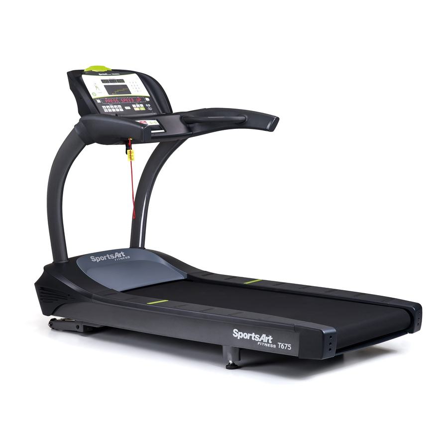
SPORTSART T621 TREADMILL
TABLE OF CONTENTS
TABLE OF CONTENTS
1. INTRODUCTION.....................................................................................................
INTRODUCTION Specifications..............................................................................
2. SAFETY PRECAUTIONS........................................................................................
3. LIST OF PARTS......................................................................................................
4. ASSEMBLING THE PRODUCT...............................................................................
STEP 0 Remove Packaging Material......................................................................
STEP 1 Install the Pedestals..................................................................................
STEP 2 Install the Display......................................................................................
STEP 3 Move the Treadmill ...................................................................................
STEP 4 Level the Treadmill....................................................................................
STEP 5 Install the Power Cord ..............................................................................
STEP 6 Align the Walk Belt....................................................................................
STEP 7 Adjust the Walk Belt Tightness..................................................................
STEP 8 Safety Key Cord Installation......................................................................
DISPLAY Overview..................................................................................................
DISPLAY Windows..................................................................................................
DISPLAY Keys.........................................................................................................
OPERATION Quick Start.........................................................................................
OPERATION Start Key............................................................................................
OPERATION Workout Programs.............................................................................
OPERATION Basic Settings....................................................................................
HEART RATE Telemetry..........................................................................................
HEART RATE Contact.............................................................................................
HOW HARD SHOULD I EXERCISE?......................................................................
HOW LONG SHOULD I EXERCISE?......................................................................
HOW OFTEN SHOULD I EXERCISE?....................................................................
MAINTENANCE Error Messages............................................................................
MAINTENANCE Fuse Replacement.......................................................................
MAINTENANCE Lubrication....................................................................................
MAINTENANCE Lubrication Prompt........................................................................
MAINTENANCE Lubrication Procedure...................................................................
MAINTENANCE Schedule.......................................................................................
MAINTENANCE Task List (Treadmills)....................................................................
MAINTENANCE One-Year Maintenance Log..........................................................
10.BLOCK DIAGRAM..................................................................................................
1
2
3
8
10
11
13
20
23
24
25
26
27
28
30
31
32
34
34
34
38
40
40
42
42
42
43
44
45
45
46
50
51
53
54
Advertisement
Table of Contents

Related Manuals for SportsArt Fitness t625


Summary of Contents for SportsArt Fitness t625
-
Page 1: Table Of Contents
SPORTSART T621 TREADMILL TABLE OF CONTENTS TABLE OF CONTENTS 1. INTRODUCTION..................... INTRODUCTION Specifications................2. SAFETY PRECAUTIONS..................3. LIST OF PARTS...................... 4. ASSEMBLING THE PRODUCT................STEP 0 Remove Packaging Material..............STEP 1 Install the Pedestals.................. STEP 2 Install the Display..................STEP 3 Move the Treadmill ................... STEP 4 Level the Treadmill.................. -
Page 2: Introduction
1. INTRODUCTION Thank you for purchasing a high quality product from SportsArt Fitness. Constructed of robust materials and built for years of trouble-free usage, the SportsArt T621 Treadmill was designed and manufactured to become an integral part of your fitness regimen. -
Page 3: Introduction Specifications
INTRODUCTION Specifications T621 treadmill product specifications follow: Speed range: 0.1 to 12.0 mph; 0.2 to 20 kph Incline range: 0 to 15% Motor: 3.2 hp Display type: LED Running surface: 22 x 61 inches; 508 x 1473 mm Workout programs: Programmable interval, random, hill (x3), glute (30-minute and 45- minute programs), quick start, manual/track Heart rate control programs: weight loss, cardio conditioning, ZoneTrainer™... -
Page 4: Safety Precautions
2. SAFETY PRECAUTIONS IMPORTANT SAFETY PRECAUTIONS are not Such parts... - Page 5 The user weight limit for this treadmill is 180 kg (400 lb.). Note that the top speed setting of 12 mph (20 kph) is suitable for users of up to 125 kg (275 lb.). Note also that speed may automatically decrease to avoid the overload of electronic components.
- Page 6 The expense to correct such interference must be borne by the product owner or operator. WARNINGS AND CAUTIONS(FRENCH)
- Page 7 180kg (400 125kg (275 20 Amp 10 Amp ‧Ce tapis n'est pas destiné à être utilisé par des personnes (y compris des enfants) dont les capacités physiques, sensorielles ou mentales sont réduites ou qui ne disposent pas de l'expérience ou du savoir nécessaires, sauf si celles-ci ont au préalable été formées eu égard à...
- Page 8 Remarque: Ce matériel a été testé et déclaré conforme aux normes des appareils digitaux de Classe B, conformément à la partie 15 du Règlement de la FCC. Ces limites sont conçues pour offrir une protection raisonnable contre les interférences nuisibles dans une installation résidentielle. Cet appareil génère, utilise, et peut diffuser des signaux radioélectriques, et, s'il n'est pas installé...
-
Page 9: List Of Parts
3. LIST OF PARTS Assembly Parts Name Qty No. Description Display Left pedestal Handlebar assembly Owner manual Right pedestal Hardware kit Feeder cord Power cord Water guard ring Applicator tube Main frame Silicone lubricant Right side cover Left side cover... - Page 10 Parts in the Hardware Kit Name Name Specification Specification Notes Notes Screw cover (rounded) Screw cover (flat) Mushroom top Phillips screw M4*L16 Screw socket Screw clip 15A-100V~110V Fuse 10A-200V~220V L-shaped Allen wrench L-shaped Allen wrench L-shaped Allen wrench T-shaped Allen wrench Double open-end wrench green Screwdriver handle...
-
Page 11: Assembling The Product
4. ASSEMBLING THE PRODUCT Please follow instructions below to assemble this treadmill. Note: For brevity, throughout this manual, the word “screws” is used where screws, washers, and other hardware may be involved. Also, the words “left” and “right” are used in reference to the product and its parts. -
Page 12: Step 0 Remove Packaging Material
STEP 0 Remove Packaging Material Remove packaging material in order A, B, and C as shown to place the treadmill on its cardboard box. A. Cut the corners of the cardboard box to lay the box flat. B. Lift the back end of the treadmill and remove packaging material in the back and center of the treadmill. - Page 13 Please make sure that the walk belt runs below the walk belt guides. Walk belt guides should press the walk belt down on both sides. If the walk belt is on top of the guides, loosen screws at position A. Place the walk belt below the guides as shown. Then readjust walk belt tightness per instructions in part 6.
-
Page 14: Step 1 Install The Pedestals
STEP 1 Install the Pedestals -13-... - Page 15 Remove screws (41) from the pedestal mount area. Inspect whether the screw sockets in areas A and B are in place on the product. If not, remove them from the hardware kit and insert them into place on the product. Note: If you intend to install the CardioActive™...
- Page 16 Follow steps (a) through (d) in order to thread the data cable through the right pedestal. (a) In the right pedestal mount area, the data cable is secured with a zip tie. Carefully cut the zip tie to free the data cable. Pull the data cable through the oval opening. (b) Place the right pedestal (A3) flat on the floor, with the bottom area of the pedestal nearest to the data cable.
- Page 17 Hold the data cable at the top of the right pedestal (A3), and insert the bottom of the pedestal onto the pedestal mount. Avoid pinching or crimping the data cable. Place the water guard (A5) on the pedestal higher than the motor cover. Loosely secure the right pedestal (A3) with screws (41).
- Page 18 Follow steps (a-e) to install handlebars. (a) First, remove the screws (42, 43) from the handlebar assembly (A2). (b) Insert the left side of the handlebar (A2) into the left pedestal (A7). (c) Connect the cables in area A from the right pedestal (A3) and from the handlebar (A2).
- Page 19 (d) Tuck cables into the pedestal safely. Then insert the right side of the handlebar assembly (A2) into the right pedestal (A3), without pinching or crimping cables. (e) Thread screws in place by hand. First, secure screws (42) in area B. Then secure screws (43) in area C.
- Page 20 After handlebars are secured in place, fully secure screws in area A on both sides of the treadmill. Snap left and right side covers (A6a, A6b) into place and secure them with screws (33). Then slide the water guard (A5) into place on the motor cover. -19-...
-
Page 21: Step 2 Install The Display
STEP 2 Install the Display -20-... - Page 22 Follow steps (a-g) below to install the display assembly. (a) Remove screws (44) from the handlebar (A2). (b) Insert the display (A1) onto the handlebar assembly (A2). Note: Aim properly to avoid damaging the display board. (c) Then slightly lift the display (A1) (d) Temporarily secure the display by inserting it as indicated by arrows.
- Page 23 Connect cables in areas A and B. ( ) After connecting cables, tuck them away for safety. Then slightly lift the display (A1) and press it into place. Note: In area C, the display cover must be outside of the handlebar cover.
-
Page 24: Step 3 Move The Treadmill
STEP 3 Move the Treadmill First, place hands under the frame in area A, lift the treadmill, then roll it into position as desired. -23-... -
Page 25: Step 4 Level The Treadmill
STEP 4 Level the Treadmill Press on points A and B to inspect whether the unit is stable and level on theground. If not, please level the treadmill by following instructions (a, b and c): (a) First, loosen leveler nuts. (b) Adjust leveler feet downward until the treadmill is level and does not rock. -
Page 26: Step 5 Install The Power Cord
STEP 5 Install the Power Cord Please follow instructions below to install the power cord onto the treadmill. (a) First remove screws (45) from the power cord connector on the product. (b) Insert the end of the power cord into the connector on the product. (c) Secure the power cord screws (34) as shown (c). -
Page 27: Step 6 Align The Walk Belt
STEP 6 Align the Walk Belt The walk belt should run in the center of the deck, with an even amount of space on both sides, between the belt edges and the landing strips. If the space on either side is not the same, rotate rear roller screws about one-half turn at a time. -
Page 28: Step 7 Adjust The Walk Belt Tightness
STEP 7 Adjust Walk Belt Tightness As you exercise, does the walk belt suddenly pause and then regain traction? Or, if you bear down against the walk belt, does the belt not pause whatsoever? If either of these two conditions occur, the walk belt may be too loose or too tight. In this case, please turn off the treadmill and adjust walk belt tightness. -
Page 29: Step 8 Safety Key Cord Installation
STEP 8 Safety Key Cord Installation For home use, do not secure the safety key onto the product. Safety regulations require that the safety key be detachable to prevent unsupervised product use of the treadmill by children. For light commercial use, the safety key can be secured to the treadmill to prevent the key from being removed and lost. - Page 30 Secure the safety key to the treadmill as follows in steps (f)-(h) ( ) Remove one screw on the left as shown. (g) Put the safety key in its place. (h) Insert the screw back into the loop. Secure the screw back into place. Bend the loop downward 90°.
-
Page 31: Understanding The T621 Display Console Display Overview
5. UNDERSTANDING THE T621 DISPLAY CONSOLE DISPLAY Overview The T621 treadmill is designed for user convenience. With better feedback about your workout, you get better results. The following explains the display window and key functions. Please read this manual, understand the display functions, and thereby get optimum enjoyment and benefit from this product. -
Page 32: Display Windows
DISPLAY Windows CardioAdvisor™ helps you maintain a workout heart rate to meet your fitness goals. ■ WT LOSS 65% shows the optimum heart rate zone for weight loss workouts. ■ HEART RATE shows the actual heart rate. Range: 40 to 250 beats per minute ■... -
Page 33: Display Keys
DISPLAY Keys Below is a brief introduction to display keys and their functions. QUICK START – Press this key to immediately begin exercising, without first inputting user information. START – Press this key to begin exercising after inputting user information. ENTER –... - Page 34 SPEED UP/DOWN – Press these keys to control the speed of the walk belt. The SPEED UP key also acts like QUICK START. At the start of a workout, press the SPEED UP key to activate the walk belt. STOP/HOLD TO RESET – This key has two functions: pause and reset. When exercising, press this key to pause.
-
Page 35: Operating The T621 Treadmill
6. OPERATING THE T621 TREADMILL OPERATION Quick Start ▲ Start Key OPERATION Press the START key to begin exercising without the benefit of user information. ▲/▼ ▲/▼ OPERATION Workout Programs -34-... - Page 36 This product has three heart rate control programs: weight loss, cardio conditioning, and zone trainer. In heart rate control programs, the treadmill automatically adjusts incline or speed to help you maintain an ideal target heart rate to meet your fitness goals.
- Page 37 HILL – There are three hill programs. Press the hill key to toggle between programs 1, 2, and 3. When your preferred hill workout illustration appears, press the ENTER key to confirm your choice. The following prompt appears: “TIME-1 DIST-2”. Press INCLINE▲ /▼...
- Page 38 “INCL-1 SPEED-2” “SELECT SPEED OR INCLINE PROGRAM” appears on the display. You can choose either incline or speed as the variable to maintain your target heart rate. Press numeric keys to select incline (1) or speed (2). If you choose incline, the workout can begin. Press the SPEED▲ key to begin exercising.
-
Page 39: Operation Basic Settings
Press INCLINE▲/▼ keys or numeric keys to establish a maximum speed. Then press the ENTER key to confirm your choice. At this point, the workout can begin. Press the SPEED▲ key to begin exercising. Speed will gradually increase until the maximum speed or the target heart rate is reached. - Page 40 DISPLAY BOARD IC VERSION The display will show “CTL xxxxx-xx” where “x” represents either alphabetical or numerical digits. This is the display board program IC version number. Press the ENTER key to proceed to view the drive board program IC version. DRIVE BOARD IC VERSION The display will show “DRV xxxxx-xx”...
-
Page 41: About Heart Rate Detection And Presentation
7. ABOUT HEART RATE DETECTION AND PRESENTATION Heart rate detection functions are optional and may not be included in your particular model. If your product is equipped with these functions, please note the following information. HEART RATE Telemetry The word "telemetry heart rate" refers to the detection of the heart rate, usually via a strap worn on the exerciser's chest and transmitted over the air for reception by a receiver built into the product. - Page 42 4.The vibration of treadmills at speeds over 4 mph / 6.4 kph makes heart rate detection difficult. Also, if your hands move, heart rate detection becomes difficult. SUGGESTIONS For better heart rate detection, keep hands in one place on the contact plates. Or wear a telemetry heart rate strap on your chest.
-
Page 43: Guidelines For Exercise How Hard Should I Exercise
8. GUIDELINES FOR EXERCISE HOW HARD SHOULD I EXERCISE? Studies show that to achieve the benefits of aerobic exercise, it is necessary to work within your training zone. Your training zone depends on your age and level of fitness. The above chart indicates the recommended Heart Rate training zones (darkened area of the chart). -
Page 44: Maintenance
9. MAINTENANCE MAINTENANCE Error Messages The following messages can appear on this product for diagnostic purposes. ERR1 – Optic sensor error. The main program IC has not received the optic sensor signal. Re-start the unit to see if normal operation will resume. ERR3 –... -
Page 45: Maintenance Fuse Replacement
MAINTENANCE Fuse Replacement If current becomes too high, the fuse breaks. This protects the product. To replace a fuse, follow instructions (a-g) below. (a) Press inward on the fuse cap. (b) Turn the fuse cap counterclockwise. (c)The fuse and fuse cap springs out. (d) Remove the burnt fuse. -
Page 46: Maintenance Lubrication
MAINTENANCE Lubrication Periodic maintenance is crucial to the performance of fitness equipment, just like it is to the performance of an automobile. The better you maintain a product, the longer it will serve your needs. This treadmill requires periodic lubrication of the walk belt and has a built-in system to prevent overuse without maintenance. -
Page 47: Maintenance Lubrication Procedure
MAINTENANCE Lubrication Procedure Remove screws from the left end cap. Then remove the left end cap. Remove screw covers and screws from the left landing strip. Then remove the left landing strip. -46-... - Page 48 Remove screws from the left finger guard. Note the position of the finger guard. Then remove the left finger guard. Simultaneously press and hold INCLINE▲+ INCLINE▼+ 0 keys for two seconds. This activates the lubrication mode. The treadmill will operate at low speed. At this point, ▲▼...
- Page 49 Hold the applicator tube in place for about three minutes to allow the lubricant to disperse. 8. Once the lubrication mode is activated, the message “PLEASE PRESS THE STOP KEY AFTER FINISHING LUBRICATION” will appear on the screen. At this point, press the STOP key to deactivate the lubrication mode.
- Page 50 10. Secure the left landing strip. Secure the left end cap. 12. Note: The lubrication mode can be activated at any time. If you notice a buildup of static electricity or that the bottom side of the walk belt is dry, applying lubricant may help.
-
Page 51: Maintenance Schedule
MAINTENANCE Schedule (T621) Maintenance Schedule Area Unit exterior Clean. Inspect for looseness. Screws Tighten if needed. Inspect alignment. Inspect for wear. Lubricate with Walk belt SportsArt lubricant. Inspect for wear. Deck Inspect for normal rotation. Guide wheel Front roller Inspect for normal rotation. Inspect for normal rotation. -
Page 52: Maintenance Task List (Treadmills)
MAINTENANCE Task List (Treadmills) Like cars, fitness products require maintenance. Regular maintenance extends product life, and failure to maintain products can void the manufacturer's warranty. Copy the maintenance log sheet, and record maintenance work for each fitness product. Daily tasks 1. - Page 53 turned off. For safety, turn off unit power. Wait five minutes to allow capacitors to discharge. Then disconnect the power cord from the wall socket (if applicable). Only after such steps have been completed should covers be removed and electronic components accessed.
-
Page 54: Maintenance One-Year Maintenance Log
MAINTENANCE One-Year Maintenance Log Facility : Supervisor: Product Model Number : Serial Number: Start Date: End Date: Daily Tasks Weeks 8-14 Weeks 1-7 Weeks 15-21 Weeks 22-28 Completed Daily Tasks Weeks 29-35 Weeks 36-42 Weeks 43-49 Weeks 50-52 Completed Weekly Tasks Weeks 1-7 Weeks 8-14 Weeks 15-21... -
Page 55: Block Diagram
10. BLOCK DIAGRAM T621 Your Authorized Distributor -54-...
Need help?
Do you have a question about the t625 and is the answer not in the manual?
Questions and answers