Table of Contents
Advertisement
CHAPTER 1: SAFETY INSTRUCTIONS
1.1 SAFETY PRECAUTIONS....................................................................................
1.2 ABOUT THIS MANUAL.......................................................................................
2.1 INTRODUCTION.................................................................................................
2.2 SPECIFICATIONS...............................................................................................
2.3 COMPONENTS IN THE CARTON......................................................................
2.4 COMPONENTS IN THE HARDWARE KIT..........................................................
2.5 COMPONENTS ON THE PRODUCT..................................................................
3.1 INSTALLATION REQUIREMENTS....................................................................
3.2 ASSEMBLY INSTRUCTIONS.............................................................................
STEP 1 Assemble the Left and Right Pedestals and Handlebars.....................
STEP 2 Install the Display.................................................................................
STEP 3 How to Move the Treadmill...................................................................
STEP 4 Leveling the Unit...................................................................................
STEP 5 Align the Walk Belt................................................................................
STEP 6 Adjust Walk Belt Tightness...................................................................
STEP 7 Install the Power Cord..........................................................................
3.3
SAFETY KEY USAGE........................................................................................
4.1 DISPLAY LAYOUT...............................................................................................
4.2
DISPLAY FUNCTIONS........................................................................................
4.3
DISPLAY KEYS...................................................................................................
4.4
SAFETY FEATURES...........................................................................................
5.1 STARTING YOUR TREADMILL...........................................................................
5.2 QUICK START......................................................................................................
5.3 WORKOUT SETUP..............................................................................................
5.4 WORKOUT PROGRAMS.....................................................................................
5.5 USER PARAMETER SETTINGS.........................................................................
6.1 HEART RATE TELEMETRY................................................................................
6.2 CONTACT HEART RATE....................................................................................
TABLE OF CONTENTS
...............................................................................
1
5
6
7
8
9
9
10
10
13
20
23
24
25
26
27
28
29
31
31
32
34
35
35
35
36
37
38
38
Advertisement
Table of Contents

Subscribe to Our Youtube Channel
Related Manuals for SportsArt Fitness T621


Summary of Contents for SportsArt Fitness T621
-
Page 1: Table Of Contents
CHAPTER 4: T621 DISPLAY 4.1 DISPLAY LAYOUT....................DISPLAY FUNCTIONS..................DISPLAY KEYS....................SAFETY FEATURES................... CHAPTER 5: HOW TO USE YOUR T621 TREADMILL 5.1 STARTING YOUR TREADMILL................5.2 QUICK START...................... 5.3 WORKOUT SETUP....................5.4 WORKOUT PROGRAMS..................5.5 USER PARAMETER SETTINGS................. CHAPTER 6: ABOUT HEART RATE DETECTION AND PRESENTATION 6.1 HEART RATE TELEMETRY................ - Page 2 CHAPTER 7: GUIDELINES FOR EXERCISE 7.1 HOW HARD SHOULD I EXERCISE?..............7.2 HOW LONG SHOULD I EXERCISE?..............7.3 HOW OFTEN SHOULD I EXERCISE?..............CHAPTER 8: MAINTENANCE 8.1 TREADMILL LUBRICATION KIT................. 8.2 THE LUBRICATION PROMPT................8.3 CLEARING THE SERVICE NEEDED MESSAGE..........8.4 MANUAL LUBRICATION PROCEDURE............
-
Page 3: Safety Precautions
- CHAPTER 1 SAFETY PRECAUTIONS 1.1 SAFETY PRECAUTIONS... - Page 4 DO NOT use accessories that are not specifically recommended by the manufacturer. Such parts might cause injuries or cause the unit to fail.
- Page 5 180 KGS (400 LBS). Note that the 12 mph (20 kph) rating good up to 125 kgs (275 lbs). Note that the rating is good for users up to 150 (330 (400 (330 20 Amp 10 Amp...
- Page 6 Improper connection of the equipment-grounding connector can result in a risk of electric shock. Check with a qualified electrical or service person if you are in doubt as to whether the treadmill is properly grounded. DO NOT modify the plug provided with the product; if it doesn't fit the outlet, have the proper outlet installed by a qualified technician.
-
Page 7: About This Manual
1.2 ABOUT THIS MANUAL This manual provides instructions for the assembly, installation, and operation of the SportsArt T621 Treadmill. Please study this manual thoroughly to prevent injury to exercisers and damage to the product. Please save these instructions for future reference. -
Page 8: Chapter 2 Unpacking The Treadmill
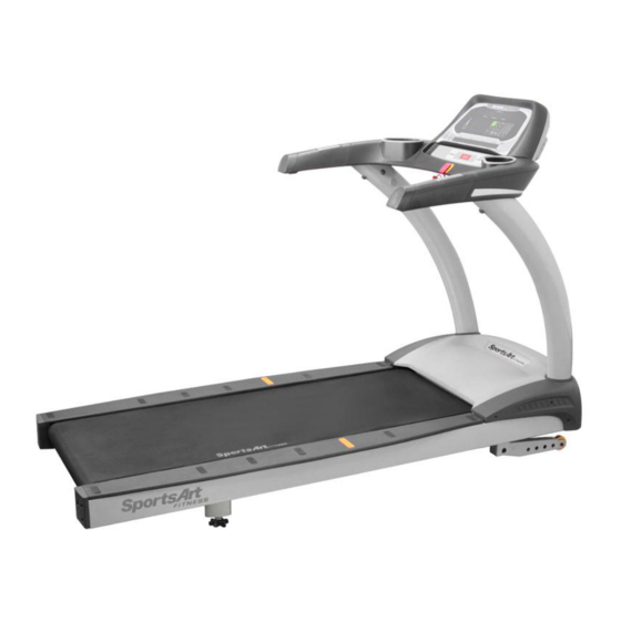
2.1 INTRODUCTION Thank you for purchasing a high quality product from SportsArt Fitness. Constructed of robust materials and built for years of trouble-free usage, the SportaArt T621 Treadmill was designed and manufactured to become an integral part of your fitness regimen. -
Page 9: Specifications
2.2 SPECIFICATIONS T621 Specifications Running surface: 22" x 61" inches Speed Range: 0.1- 12 mph; 0.2- 20 kph; Motor: 3.2 HP Incline Range: 0-15% Programs: MANUAL, HILL, RANDOM, INTERVAL, QUICK START, WT LOSS, CARDIO, GLUTE, ZONE TRAINER Feedback: CALORIES, SPEED, TIME, DISTANCE, CAL/HR, METS, PACE, INCLINE, HEART RATE, WT LOSS 65%, CARDIO 80%. -
Page 10: Components In The Carton
2.3 COMPONENTS IN THE CARTON Assembly Parts Name Qty No. Description Display Left pedestal Handlebar assembly Owner manual Right pedestal Hardware kit Feeder cord Power cord Waterproof ring Applicator tube Main frame Silicone lubricant Right side cover Left side cover... -
Page 11: Components In The Hardware Kit
2.4 COMPONENTS IN THE HARDWARE KIT A hardware kit is provided in the packaging of this product. Please inspect the hardware kit for the following items. Hardware Kit Name Name Specification Specification Notes Notes Screw cover (rounded) Screw cover (flat) Mushroom top Phillips screw M4*L16 Screw socket... -
Page 12: Chapter 3 Product Assembly
- CHAPTER 3 PRODUCT ASSEMBLY 3.1 INSTALLATION REQUIREMENTS The challenge of product installation depends highly on the area in which the product will be used. Stairs, doorways and other obstacles must be considered in planning for product installation. Please ensure the safety of people and property in planning the installation of any product. - Page 13 Remove packaging material in order A B and C as shown to set the treadmill flat on its cardboard box A Cut the corners of the cardboard box to lay the box flat B Lift the back end of the treadmill and remove packaging material in the back and center of the treadmill C Lift the front end of the treadmill and remove packaging material at the front end of the treadmill...
- Page 14 Please make sure that the walk belt runs below the walk belt guides. Walk belt guides should press the walk belt down on both sides. If the walk belt is on top of the guides, loosen screws at position A. Place the walk belt below the guides as shown. Then readjust walk belt tightness per instructions in part 6.
-
Page 15: Step 1 Assemble The Left And Right Pedestals And Handlebars
STEP 1 Assemble the Left and Right Pedestals and Handlebars -13-... - Page 16 1-1. Remove screws (41) from the pedestal mount area. Inspect whether the screw sockets in areas A and B are in place on the product. If not, remove them from the hardware kit and insert them into place on the product. -14-...
- Page 17 1 2. Follow steps a d) in order to thread the data cable through the right pedestal a In the right pedestal mount area the data cable is secured with a zip tie Carefully cut the zip tie to free the data cable Pull the data cable through the oval opening b Place the right pedestal A3 flat on the floor with the bottom area of the pedestal nearest to the data cable Disconnect the feeder cord A4 from the bottom of the pedestal Then attach the feeder cord A4) to the top part of the data cable...
- Page 18 1-3. Hold the data cable at the top of the right pedestal (A3), and insert the bottom of the pedestal onto the pedestal mount. Avoid pinching or crimping the data cable. Place the water guard (A5) on the pedestal higher than the motor cover. Loosely secure the right pedestal (A3) with screws (41).
- Page 19 1-4. Follow steps (a~e) to install handlebars. First, remove the screws (42, 43) from the handlebar assembly (A2). Insert the left side of the handlebar (A2) into the left pedestal (A7). Connect the cables in area A from the right pedestal (A3) and from the handlebar (A2).
- Page 20 (d) Tuck cables into the pedestal safely. Then insert the right side of the handlebar assembly (A2) into the right pedestal (A3), without pinching or crimping cables. (e) Thread screws in place by hand. First, secure screws (42) in area B. Then secure screws (43) in area C.
- Page 21 1 5. After handlebars are secured in place fully secure screws in area A on both sides of the treadmill Snap left and right side covers A6a A6b into place and secure them with screws 33 Then slide the water guard A5 into place on the motor cover -19-...
-
Page 22: Step 2 Install The Display
STEP 2 Install the Display -20-... - Page 23 2-1. Follow steps (a~g) below to install the display assembly. Remove screws (44) from the handlebar (A2). Insert the display (A1) onto the handlebar assembly (A2). Note: aim properly to avoid damaging the display board. Then slightly lift the display (A1) Temporarily secure the display by inserting it as indicated by arrows.
- Page 24 Connect cables in areas A and B. After connecting cables, tuck them away for safety. Then slightly lift the display (A1) and press it into place. Note: In area C, the display cover must be outside of the handlebar cover. Use screws (44) to secure the display (A1) in place.
-
Page 25: Step 3 How To Move The Treadmill
STEP 3 How to Move the Treadmill First, place hands under the frame in area A, lift the treadmill, then roll it into position as desired. -23-... -
Page 26: Step 4 Leveling The Unit
STEP 4 Level the Unit 4-1. Press on points A and B to inspect whether the unit is stable and level on theground. 4-2. If not, please level the treadmill by following instructions (a, b, c): First, loosen leveler nuts. Adjust leveler feet downward until the treadmill is level and does not rock. -
Page 27: Step 5 Align The Walk Belt
STEP 5 Align the Walk Belt The walk belt should run in the center of the deck, with an even amount of space on both sides, between the belt edges and the landing strips. If the space on either side is not the same, rotate rear roller screws about one-half turn at a time. -
Page 28: Step 6 Adjust Walk Belt Tightness
STEP 6 Adjust Walk Belt Tightness As you exercise, does the walk belt suddenly pause and then regain traction? Or, if you bear down against the walk belt, does the belt not pause whatsoever? If either of these two conditions occur, the walk belt may be too loose or too tight. In this case, please turn off the treadmill and adjust walk belt tightness. -
Page 29: Step 7 Install The Power Cord
STEP 7 Install the Power Cord 7-1. First remove screws (45) from the power cord socket on the product. 7-2. Insert the power cord into place on the product. 7-3. Secure power cord connector screws (45). Then insert the other end of the power cord into the appropriate power supply socket in the wall. -
Page 30: Step 8 Replacing The Fuse
STEP 8 Replacing the Fuse If current becomes too high, the fuse breaks. This protects the product. To replace a fuse, follow instructions (a~g) below. (a) Press inward on the fuse cap. (b) Turn the fuse cap counterclockwise. The fuse and fuse cap springs out. (d) Remove the burnt fuse. -
Page 31: Safety Key Usage
3.3 SAFETY KEY USAGE For home use, do not secure the safety key onto the product. Safety regulations require that the safety key be detachable to prevent unsupervised product use of the treadmill by children. For light commercial use, the safety key can be secured to the treadmill to prevent the key from being removed and lost. - Page 32 Secure the safety key to the treadmill as follows in steps f~h. ( ) Remove one screw on the left as shown. (g) Put the safety key in its place. (h) Insert the screw back into the loop. Secure the screw back into place. Bend the loop downward 90°.
-
Page 33: Chapter 4 T621 Display
- CHAPTER 4 T621 DISPLAY 4.1 DISPLAY LAYOUT Illustration screen Feedback screen Speed keys Incline keys 4.2 DISPLAY FUNCTIONS (1) SPEED 0.1 ~ 12 MPH or 0.2 ~ 20 KPH (2) INCLINE 0 ~ 15% (increases/decreases in increments of 0.5) -
Page 34: Display Keys
DISPLAY KEYS The following explains key functions briefly. For a more thorough explanation, refer to the treadmill operation section. 1. START Press the START key to exercise with the benefit of user information. Then follow prompts to proceed. 2. QUICK START The QUICK START key allows you to start exercising immediately without first inputting age and weight information. - Page 35 9. ZONE TRAINER The ZONE TRAINER program turns any workout into a heart rate control workout. It makes your current heart rate your heart rate target. The incline position will automatically adjust to maintain your target heart rate. 10. CARDIO The CARDIO program is a heart rate control program that maintains a target heart rate in the optimal range for cardio conditioning.
-
Page 36: Safety Features
17. CHANGE DISPLAY / SCAN While working out, press the CHANGE DISPLAY/SCAN key to control workout feedback. There are two rows of workout feedback. The top row shows calories, speed, time and distance. The bottom row shows cal/HR, MET, pace and incline. An LED near the rows lights to indicate the active row of feedback. -
Page 37: Chapter 5: How To Use Your T621 Treadmill
CHAPTER 5-HOW TO USE YOUR T621 TREADMILL 5.1 STARTING YOUR TREADMILL Your SportsArt Fitness treadmill has many outstanding electronic features that can help you get the most out of your workout. By thoroughly understanding the display functions, you can greatly improve your workout experience. Please read the following instructions to begin your workout. -
Page 38: Workout Programs
COOL DOWN Upon completing the workout, accumulative workout data will appear on the display. Then a COOL DOWN mode will begin. Treadmill speed will gradually slow to 0.0 MPH/KPH, and incline will decline to 0% within two minutes. 5.4 WORKOUT PROGRAMS Below are details about specific workout programs. -
Page 39: User Parameter Settings
5.5 USER PARAMETER SETTINGS User parameters determine basic operating features. To change these parameters, please follow up the instructions below. A. When the banner SPORTSART T621 is displayed, hold the CHANGE button for 3 ▲ ▼ seconds. Press INCLINE to select US standard or Metric units. -
Page 40: Chapter 6: About Heart Rate Detection And Presentation
- CHAPTER 6 ABOUT HEART RATE DETECTION AND PRESENTATION Heart rate detection functions are optional and may not be included in your particular model. If your bike is equipped with these functions, please note the following information. 6.1 HEART RATE TELEMETRY The word "telemetry heart rate"... - Page 41 4.The vibration of treadmills at speeds over 4mph/6.4kph makes heart rate detection difficult. Also, if your hands move, heart rate detection becomes difficult. SUGGESTIONS For better heart rate detection, keep hands in one place on the contact plates. Or wear a telemetry heart rate strap on your chest. NOTE: AVOID STATIC ELECTRICITY In cold, dry areas, static electricity can interfere with unit operation.
-
Page 42: Chapter 7 Guidelines For Exercise
- CHAPTER 7 GUIDELINES FOR EXERCISE 7.1 HOW HARD SHOULD I EXERCISE? Studies show that to achieve the benefits of aerobic exercise, it is necessary to work within your training zone. Your training zone depends on your age and level of fitness. -
Page 43: Chapter 8 Maintenance
Item: LUBE-02 Periodic lubrication of this treadmill walk belt is so important that lubricant is provided with this treadmill. More lubrication kits can be found by contacting SportsArt Fitness. 8.2 THE LUBRICATION PROMPT When the walk belt total rotation distance exceeds 2500 miles/4000 KM and the lubrication period memory has not been cleared, the prompt ”SERVICE NEEDED APPLY... - Page 44 Remove screws from the left end cap. Then remove the left end cap. Remove screw covers and screws from the left landing strip. Then remove the left landing strip. -42-...
- Page 45 Remove screws from the left metal bracket. Note the position of the left metal bracket. Then remove the left metal bracket. ▲ ▼ Simultaneously press and hold INCLINE + INCLINE + 0 keys for two seconds. The treadmill will operate at low speed. At this point, no UP or DN keys will operate Apply 50 cc from the bottle of liquid lubricant.
- Page 46 While the ”SERVICE NEEDED- APPLY LUBE” message appears, simultaneously press and hold INCLINE + INCLINE + 0 keys for two seconds. The motor will operate at a low speed. Hold the applicator tube in place for about three minutes to allow the lubricant to disperse.
- Page 47 10. Secure the left landing strip. Secure the left end cap. 12. Note: The physical task of lubricating the treadmill can be done at any time. To activate the lubrication mode, when the start up banner, SPORTSART-XXX, is displayed, simultaneously press and hold INCLINE + INCLINE + 0 keys for two seconds.
-
Page 48: Clearing The Service Needed Message
8.3 CLEARING THE SERVICE NEEDED MESSAGE A. When the ”SERVICE NEEDED- APPLY LUBE” message appears, simultaneously ▲ ▼+ press and hold INCLINE +INCLINE 0 for two seconds. The motor will operate at a low speed, allowing lubricant to spread evenly on the walk belt. The display will show the following message: ”PLEASE PRESS THE STOP KEY AFTER FINISHING LUBRICATION”. - Page 49 3. Check walk belt tension and alignment. Adjust if necessary. Do not over tighten. Quarterly tasks Use a lint-free towel and diluted Simple Green to clean the walk deck. Lubricate the walk deck with SportsArt Hyperglide™ lubricant, part lube-03, and cancel the lubrication prompt (see manual).
- Page 50 d. Note: Turning rear roller screws clockwise extends the rear roller toward the back of the unit, increasing walk belt tension. Turning rear roller screws counterclockwise brings the rear roller closer toward the front of the unit, decreasing walk belt tension. By adjusting one screw clockwise, that side of the roller extends toward the back of the treadmill, forcing the walk belt toward the other side.
- Page 51 One-Year Maintenance Log for Treadmills Facility Name: Maintenance Supervisor: Product serial number: Start Date: End Date: Daily Tasks Week1 Week2 Week3 Week4 1.Safe 2.Clean Daily Tasks Week5 Week6 Week7 Week8 1.Safe 2.Clean Daily Tasks Week9 Week10 Week11 Week12 1.Safe 2.Clean Monthly Tasks Months 1-3 Months 4-6...
-
Page 52: Wiring Schematic
WIRING SCHEMATIC: T621 Your Authorized Distributor -50-...
Need help?
Do you have a question about the T621 and is the answer not in the manual?
Questions and answers