Table of Contents
Advertisement
Advertisement
Table of Contents

Related Manuals for SportsArt Fitness T620


Summary of Contents for SportsArt Fitness T620
- Page 1 T620/T625 Treadmill Repair Manual SPORTS ART INDUSTRIAL CO., LTD.
-
Page 2: Table Of Contents
1-1-1. T620/T625 Product Picture 1-1-2. T620/T625 Treadmill Components – (1) Display Area 1-1-3. T620/T625 Treadmill Components – (2) Motor Area 1-1-4. T620/T625 Display Components – (3) Display Board Front 1-1-6. T620/T625 Display Components – Display Board Back 1-1-7. T620/T625 Drive Board Components 1-1-8. - Page 3 4-1-1. Display Board Cable Connections 4-2-1. Drive Board Cable Connections 5. Cable Connections 5-1. Display Board 5-1-1. T620/T625 Display Board Cable Connections 5-1-2. T620/T625 Display Board Components 5-1-3. T620/T625 Display Board LED Indicators 5-1-4. T620T/625 Display Board Cable Connections 5-2. Drive Board 5-2-1 T620/T625 Drive Board Cable Connections 5-2-2.
- Page 4 【Table of Contents】 6. Error Messages 6-1-1. ERR1-Motor Does Not Rotate (Continued through 6-1-3) 6-2-1. ERR1-Motor Does Rotate (Continued through 6-2-3) 6-3-1. ERR3 (Continued through 6-3-3) 6-4-1. ERR7 (Continued through 6-4-3) 6-5-1. Display Key Malfunction (Continued through 6-5-2) 6-6-1. Unit Does Not Turn On (Continued through 6-6-3) 6-7-1.
- Page 5 7-18-1 HTR Board LED Indicators (Continued to 7-20-2) 7-19-1 7-21-1 HTR System Continuity Test 8. Mechanical Adjustments and Part Replacement 8-1. T620/T625 Treadmill Walk Belt Tightness Adjustment 8-2.AC Motor Incline Calibration Procedure - Software 8-3.AC Motor Incline Calibration Procedure - Hardware...
-
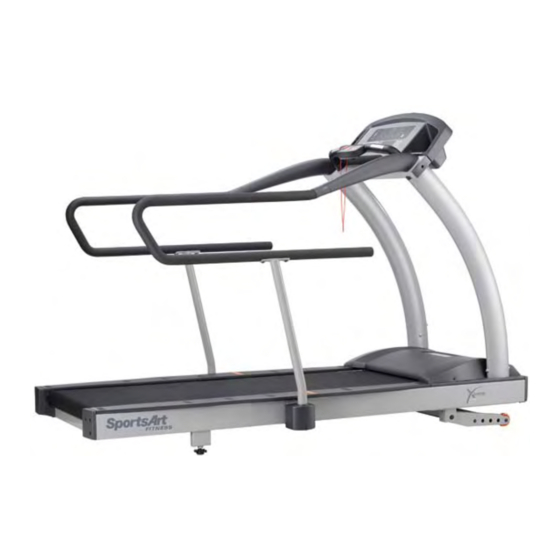
Page 6: T620/T625 Product Picture
1.T620/T625 Product Picture 1-1-1... -
Page 7: T620/T625 Treadmill Components - (1) Display Area
2.T620/T625 Treadmill Components-(1) Display Area Display HTR Handlebar (left) HTR Handlebar (right) Key Pad 1-1-2... -
Page 8: T620/T625 Treadmill Components - (2) Motor Area
3.T620/T625 Treadmill Components-(2) Motor Area Transformer EMI Filter Calibration Incline Motor Switch Optic Motor Wheel Drive Board Motor Thermal Sensor Optic Sensor Inductor 1-1-3... - Page 9 4. T620/T625 Display 1-1-4...
-
Page 10: T620/T625 Display Components - (3) Display Board Front
5.T620/T625 Display Components – Display Board Front 1-1-5... -
Page 11: T620/T625 Display Components - Display Board Back
6.T620/T625 Display Components – Display Board Back 1-1-6... -
Page 12: T620/T625 Drive Board Components
7.T620/T625 Drive Board Components 1-1-7... -
Page 13: T620/T625 Display Components - Other
8.T620/T625 Display Components – Other Part Key Pad Keys Part Optic Sensor Part HRC Board 1-1-8... - Page 14 9.T620/T625 Display Components - Other Part HTR Boad Part EMI Filter 1-1-9...
-
Page 15: T620/T625 Specifications
T620/T625 Specifications Specification Details Notes Power S upply Exte rior Power Supply 110V (USA); 220V (Eu rope) HRC hea rt rate window: 65%, 80%, Heart Main Wi ndow Display Rate, alories, Speed, Time, Distance, Cal/hr, Mets, Pace, Incline Seconda ry Window... - Page 16 T620/T625 Introductions- Display Board 1. Display Window Introduction HEART RATE Window 80% Heart Rate Target 65% Heart Rate Target Shows Actual Heart Rate Shows 80% Heart Shows 65% Heart Rate Target Rate Target 1. This LED flashes when heart rate is detected.
- Page 17 T620/T625 Introductions- Display Indicators Calories & Cal/HR Window Time & Pace Window Speed & Mets Speed lit = shows speed Calories lit = shows calories Time lit = Exercise time Mets lit = shows METS value expenditure Pace lit = Pace value...
- Page 18 T620/T625 Introductions- Display Keys <CHANGE> Key <START> <QUICK START> <ENTER> Key Press to change Press Start to start. Press Quick Start to start without feedback information. entering user information. Press ENTER to confirm your choice. < INTERVAL > < RANDOM >...
- Page 19 Operation: (1) Press the SPEED <▲> key. Values in the speed window increase. Speed increases. (2) Press the SPEED <▼> key. Values in the speed window decrease. Speed decreases. (3) SPEED range: T620 0.2~20 KPH (0.1~12 MPH). T625 0.2~16 KPH (0.1~10 MPH). 3-1-1...
- Page 20 3.INCLINE Key Function Function: Set treadmill incline position. Operation: (1) Press the INCLINE<▲> key. Values in the incline window increase. Incline operates up. (2) Press the INCLINE<▼> key. Values in the incline window decrease. Incline operates down. (3)INCLINE range: 0~15%; increments of 0﹒5%. 4.STOP Key Function Function: Leave an exercise program.
- Page 21 6.CLEAR Key Function: Clear entered values to 0. Operation: Press to clear entered values to 0. 7.PROGRAM Key Function: Select exercise programs. Operation: (1) Press any PROGRAM key. Its corresponding LED lights. (2) Programs include MANUAL、HILL、RANDOM、INT、Wt LOSS、CARDIO、 ZONE TRAINER、GLUTE. 3-1-3...
- Page 22 9. Basic Settings: KPH/MPH Function: (1)KPH/MPH setting Operation: (1) Hold the <Change Display> key for three seconds to enter the basic setting mode.The present setting appears as either “UNIT - MPH” or “UNIT - KPH”. Press the INCLINE<▲/▼> key to toggle between the two settings.
-
Page 23: T620/T625 Display Board Cable Connections
1.T620/T625 Display Board Cable Connections Telemetry Key Board Receiver Board Display Board Board HTR Handlebar (left/right) Drive Board 4-1-1... - Page 24 2.T620/T625 Drive Board Cable Connections Power Display Board Cord On/Off Incline Motor Switch Filter Drive Board Inductor Calibration Switch Transformer Optic Thermal Motor Sensor Sensor 4-1-2...
- Page 25 1.T620/T625 Display Board Cable Connections Telemetry Key Board Receiver Board Display Board Board HTR Handlebar (left/right) Drive Board 5-1-1...
-
Page 26: T620/T625 Display Board Components
2.T620/T625 Display Board Components 5-1-2... -
Page 27: T620/T625 Display Board Led Indicators
3.T620/T625 Display Board LED Indicators POWER1 Indicator Lit indicates 5 VDC power supply 5-1-3... -
Page 28: T620T/625 Display Board Cable Connections
4.T620/T625 Display Board Cable Connectors CON2 CON3 CON4 CON1 To EMG STOP To heart rate board To telemetry receiver board to drive board CON5 To key board 5-1-4... -
Page 29: Drive Board
1.T620/T625 Drive Board Cable Connections Power Display Board Cord On/Off Incline Motor Switch Filter Drive Board Inductor Calibration Switch Transformer Optic Thermal Motor Sensor Sensor 5-2-1... -
Page 30: T620/T625 Drive Board Components
2. T620/T625 Drive Board Components 5-2-2... - Page 31 3. T620/T625 Drive Board LED Indicators LED2 POWER Indicator Lit indicates power supply LED10 Motor Overheat Shutoff Indicator Lit indicates motor overheat shutoff is activated LED1 SOFT Indicator Two seconds after start up, this LED lights LED5 EMG Indicator Lit indicates drive board is supplying power to motor.
-
Page 32: T620/T625 Drive Board Led Indicators
4.T620/T625 Drive Board LED Indicators LED8 ZERO Indicator Lit indicates incline is calibrated. LED6 MC Indicator Flashing indicates motor is moving. LED11 I_SENSE LED Lit indicates start up current restriction is activated. 5-2-4... -
Page 33: T620/T625 Drive Board Cable Connections
5. T620/T625 Drive Board Cable Connections CON7 CON8 To incline calibration switch To motor thermal sensor M+, M- To motor CON5 To optic sensor CON2, CON3 To display board CON1 CON6 AC1, AC2 L1, L2 To incline motor To power cord... -
Page 34: T620/T625 Drive Board Jumper Placement
6. T620/T625 Drive Board Jumper Placement 1. Using the jumper to make electrical continuity across pin 1 & 2 makes the incline operate up. 2. Using the jumper to make electrical continuity across pin 2 & 3 makes the incline operate down. - Page 35 T620/T625 Error Message: ERR 1-Motor Does Not Rotate 1. Definition: (1) Motor doesn’t rotate. (2)Display board CPU does not read the optic sensor signal. 2. Block Diagram Display Board Optic Motor Speed Sensor Signal Signal Motor Voltage Motor Inductor 2 pin...
- Page 36 3. Operation Order Part Troubleshooting 1. Display CPU ends out the motor control signal to the drive board to control motor Display speed. Board 2. If the CPU does not receive the motor speed CLOCK signal, the display shows ERR1. 1.
- Page 37 Order Part roubleshooting 13-PIN Data 1. Inspect he data cable and its connections. Cable 1. Plea se s ee basic testing on pages 7-4, 7-5, 7-6. 2. Inspect d rive board CN2, CN3 connections. Drive Board 3. Inspect N1 or L1, L2 connections. 3.
- Page 38 T620/T625 Error Message: ERR 1- Motor Rotates. 1. Definition: The motor rotates but the display CPU does not read the optic sensor signal. 2. Block Diagram Display Board OS Signal Motor Optic Sensor Drive Board (OS) Signal Optic 4-pin LED6_MC...
- Page 39 3. Operation Order Part Troubleshooting 1. Display CPU sends out the motor control signal to the drive board to control motor Display speed. Board 2. If the CPU does not receive the motor speed CLOCK signal, the display shows ERR1. 1.
- Page 40 Order Part roubleshooting 13-PIN Data 1. Inspect e data cable and its connections. Cable 1. Plea se s ee basic testing on pages 7-4, 7-5, 7-6. 2. Inspect d rive board CN2, CN3 connections. Drive Board 3. Inspect N1 or L1, L2 connections. 3.
- Page 41 T620/T625 Error Message: ERR 3 1. Definition: Display SPEED setting and actual speed differ. 2. Block Diagram Display Board Optic Motor Sensor Speed Signal Signal Motor Optic Drive Board Optic Wheel Sensor Signal LED6_MC Optic 4 pin Sensor 6-3-1...
- Page 42 3. Operation Order Part Troubleshooting isplay . Display CPU sends out the motor control signal to the drive board to control motor speed. Board . If the CPU does not receive the motor speed CLOCK signal, the display shows ERR1. 1 3-PIN Data .
- Page 43 5. Troubleshooting Order Part Troubl eshooting 1. Ins pect t he display board CON1 cable connection. Disp ard 2. Inspect 6 IC on the drive board. 3.Replace he display as a test. 13-PIN Dat 1. Inspect he data cable and its connections. Cable 1.
- Page 44 T620/T625 Error Message: ERR 7 1. Definition: Incline motor calibration malfunction: Decline order was issued 35~40 seconds but there was no calibration signal. 2. Block Diagram Display Calibration Signal AC Incline Motor LED9 INC_UP Voltage LED7 INC_DN Incline Motor Drive Board...
- Page 45 3. Operation Order Opera tion r the incline setting on the display, the display board CPU sends the INCLINE mmand signal to the drive board. isp y Board 2. If th e INCLINE is at 0% for 35 seconds and no calibration signal is received, ERR7 pears.
- Page 46 Order Part Inspection 1. Please see basic testing, pages 7-8 and 7-9. ve boa 2. Ins pect the connections of CON6 and CON7 on the drive board. 3. Re plac e the drive board as a test. 1. Please refer to basic testing 7-9. Incline Ca libration 2.
- Page 47 T620/T625 Error Message: Display Key Malfunction 1. Troubleshooting: (1) Turn on the treadmill. Do not press any key. The display key operates. (2) Press a key during operation. There is no response. 2. Block Diagram Display Board Key Cable Key Board...
- Page 48 2. Operation Orde Part Operation Display B rd 1. Display oard CPU sends signals to control speed, incline, etc. 1. Signals t avel the 9-pin cable between the key board and the display 9-PIN Cabl board. 1. SPEED, INCLINE, STOP and QUICK START are controlled from the Key oard key board 3.
- Page 49 T620/T625 Error Message: Unit Does Not Turn On 1. Circumstance of Malfunction: (1) Turn on the unit. The display does not beep or light up. 2. Block Diagram Power Cord Display Board EMI Filter F1 FUSE On/Off Switch Drive Board...
- Page 50 3. Operation Orde Operation Display B rd 1. After the display board receives VCC power, the display lights up. 13-P le 1. The driv board VBB power travels the data cable to the display. 1. After st bilizing voltage, the drive board supplies VBB and VCC Drive Board voltage.
- Page 51 5. Troubleshooting Orde Troublesho oting F1 Fuse 1. Inspe whether the F1 fuse has blown. 1. Inspe ct t he power cord connection. 2. Inspect whether the power cord is connected to the unit properly. EMI Filter 1. Pleas efer to basic testing on page 7-1. 1.
- Page 52 T620/T625 Error Message: No Telemetry Heart Rate 1. Circumstance of Malfunction: (1) There is no telemetry heart rate on the display. (2)The heart rate on the display differs from the actual heartrate. 2. Block Diagram Telemetry Heart Telemetry Display Board...
- Page 53 3. Operation Orde Operation Display Board 1. The display shows the heart rate value after receiving it. 1. The h art rate signal travels the cable to the display board. t Rat 1. The h art rate receiver board receives and transmits the heart rate Board signal to t he display board.
- Page 54 T620/T625 Error Message: Incline Does Not Operate Up or Down 1.Circumstance of Malfunction: After pressing the incline key, the display incline values change but the incline does not operate up or down. 2. Block Diagram Display Board Incline Up/Down Signal...
- Page 55 3. Operation Orde Part Operation display board CPU sends INCLINE command signals to the drive Board board t control incline operation. 1 PIN Cable 1. INCL NE command signals travel the display board to the drive board. 1. After processing incline command signals, the drive board emits voltage to ve Bo cline motor, making it operate.
- Page 56 T620/T625 Error Message: Main Fuse Broke 1. Circumstance of Malfunction: (1) Main fuse is broken. Turn on unit power. Display does not light up. (2) Replace the fuse. Turn on power. The fuse breaks again. 2. Block Diagram Display Board...
- Page 57 3. Operation Order Operation EM Fil 1. Provid voltage from the exterior power supply. Fuse an Fuse 1. When th e drive board or other components malfunction, the fuse Holder breaks. 1. Whe n th e “-” side on the On/Off switch is pressed, exterior power is On/O Swit provided to the drive board.
- Page 58 T620/T625 Error Message: Service Required 1. Definition: The motor has overheated. The unit is operating in a protective mode. 2. Block Diagram Display Thermal Sensor Signal Motor Thermal Sensor Signal Drive Board Thermal LED10_MT-OTP Sensor 6-10-1...
- Page 59 3. Operation Orde Operatio When the thermal sensor is not too hot, the sensor circuit is an electrical Motor shor Sensor 2. When th thermal sensor is too hot, the sensor circuit is an electrical open. e Bo The dri board sends the thermal sensor signal to the display.
- Page 60 T620/T625 Error Message: Heart Touch Rate (HTR) Malfunction 1. Circumstance of Malfunction: (1) Place both hands on the HTR contacts. Display shows no reaction. (2) Do not place hands on the HTR contacts. Display shows a heart rate value. 2. Block Diagram...
- Page 61 3. Operation Order Part Operation HTR ontact 1. HTR contact pads detect the user’s pulse. 1. The signal travels through two, 2-pin cables, one connected to the contact PIN C able pads each side. PIN C able 1. The 2-pin cable connects to a 5-pin cable, which connects to the HTR board. 1.
- Page 62 Testing-EMI Filter (1) A to B Test (2) C to D Test 7-1-1...
- Page 63 (3) A to E Test Test Procedure 1. Remove wires from the filter. 2. Set voltmeter to the 200 ohm setting. Place probes as indicated. 3. Normal test results are shown below. Test Points Normal Explanation Reading 0 (continuity) There should be continuity. OL means the line connection is broken. 0 (continuity) There should be continuity.
- Page 64 Troubleshooting 1. Continuity test: If there is not continuity during the A-B and C-D tests, the filter is bad. Replace it. 2. Open test: If there is a short across A-E, the filter is bad. Replace it. 7-1-3...
- Page 65 Testing-Motor Test Procedure 1. Remove motor M+, M- wire connections from the drive board. 2. Set multimeter to the 200 VDC setting. Place probes on the M+, M- wire connectors. 3. Rotate the motor. Motor should produce voltage. If there is no voltage, the motor has an electrical “open.” Inspect the motor brushes and commutator. 7-2-1...
- Page 66 Testing-Transformer Test Configuration CON1 Transformer Connections Drive Board 7-3-1...
- Page 67 Test Procedure 1. Inspect transformer wire connections at the drive board CON1 connector. 2. Set multi-meter to the AC 200V setting. 3. Turn on unit power. Place multi-meter probes on the connector for the transformer’s two red wires (or two blue wires on a 220V unit) as shown.
- Page 68 Testing-Inductor Test Procedure 1. Remove the inductor wires from the drive board. 2. Set voltmeter to the ohm setting. Place probes separately on the wire connectors. 3. Normal reading: 10 ohm or less. 4. If there is no reaction, the inductor has an electrical open. Replace it. 7-4-1...
- Page 69 Testing-Drive Motor Voltage Test Configuration 7-5-1...
- Page 70 Test Procedure 1. Set voltmeter to the 200 VDC setting. Place probes separately on the M+, M- terminals. 2. Turn on treadmill. Press SPEED<▲> up. Motor rotates. Normal reading at the lowest speed: 0.2 KPH (0.1 MPH), 5.5-6.5V (110V) or 9-11V (220V). Normal reading at highest speed: 20.0 KPH (12.0 MPH), 100-120V (110V) or 210-230V (220V).
- Page 71 Testing-Drive Board IGBT Component and LED Indicator Placement LED11 Current Restriction Indicator 7-6-1...
- Page 72 Test Procedure Turn on unit power. Do not press keys. Inspect whether the drive board LED11 lights. If lit, one or more IGBTs have an electrical short. Troubleshooting If LED11 is lit, replace IGBT Q2 and/or IGBT Q3. 7-6-2...
- Page 73 Testing-Drive Board VCC Power Drive Board VCC Power Indicator Placement LED2 VCC 7-7-1...
- Page 74 Test Procedure 1. Turn on unit power. Power switch lights up. 2. Drive board LED2 lights. Troubleshooting If the drive board VCC power indicator does not light: 1. Inspect AC1, AC2 wire connections. 2. Inspect transformer wire connections. 3. Inspect whether fuse F1 2A is broken. Replace if necessary. 4.
- Page 75 Testing-Drive Board Incline Motor Power Test Configuration LED9 INC_UP LED7 INC_DN 7-8-1...
- Page 76 Test Procedure 1. Put voltmeter to the 600 VAC setting. Place the red probe on the CON6-WHITE wire pin. To test for up voltage, place the black probe on the CON6-BLACK wire pin. To test down voltage, place the probe on the CON6-RED wire pin.
- Page 77 Testing-Incline Limiter Switch Test Configuration LED8 ZERO Indicator 7-9-1...
- Page 78 Test Procedure Put voltmeter to the 20K Ω setting. Place probes on the calibration switch pins. Touch the switch to activate it. Normal reading: 0 Ω. Turn on power. Touch the switch again. LED8 ZERO lights. Inspection Points If not as above, replace the switch and test again. 7-9-2...
- Page 79 Testing-Optic Sensor Signal Test Configuration LED6 MC Indicator Optic sensor board Optic sensor wheel 7-10-1...
- Page 80 Test Procedure 1. Make sure that the optic wheel spins in the middle of the optic sensor nibs and that there are no broken or bent teeth. 2. Inspect whether the optic sensor wire is connected properly. 3. Turn on power. Do not press any keys. Turn the motor slowly with your hand. The drive board MC indicator lights. 4.
- Page 81 Testing-Optic Sensor LED Test Configuration LED6 MC Indicator Optic Sensor Optic Wheel 7-11-1...
- Page 82 Test Procedure 1. Inspect whether the optic sensor wires are connected properly. 2. Turn on unit power. Do not press any keys. Rotate the motor slowly. 3. When the optic wheel moves, LED6 MC on the drive board flashes. 4. If the drive board MC LED does not flash, the optic sensor signal is malfunctioning. Inspection Points If the MC indicator on the drive board does not flash when the motor moves, inspect: 1.
- Page 83 Testing-Safety Key Test Configuration 7-12-1...
- Page 84 Test Procedure 1. Put voltmeter to the 200Ω setting. 2. Place probes on wires on both sides of the reed switch shown in Fig. 1. Normal reading with the magnet not in place: OL (Open Line). 3. Place probes and magnet as shown in Fig. 2. Normal reading: 0Ω. Fig.
- Page 85 Testing-AC Incline Motor Resistance Test Position 1 Test Position 2 Fig. 1 7-13-1...
- Page 86 Test Configuration Fig. 2 Test Position 7-13-2...
- Page 87 Test Procedure 1. Remove the AC incline motor wire connection from the drive board. 2. Put voltmeter to the 200 ohm setting. Place probes separately on the red and white wires of the AC wires as shown in Fig. 1. Normal reading: 22.5 ohm or less. (Readings on black and white are the same.) 3.
- Page 88 Testing-Keypad Test Configuration 7-14-1...
- Page 89 Test Procedure 1. Put the voltmeter to the 200 ohm setting. Place probes separately on key switch points A and B. 2. Do not press any keys. Voltmeter shows no reaction: OL (open line). 3. Press a key. Voltmeter shows 0 ohm. Circumstance of Malfunction 1.
- Page 90 Testing-Display Board VBB Circuit Test Configuration 7-15-1...
- Page 91 Test Procedure 1. Turn on power. Drive board LED2 lights. 2. Put multi-meter to the DC 20 VDC setting. Place probes as shown. 3. Normal reading: about 15~16 VDC. Inspection Points If there is not 15~16 VDC, inspect: 1. Data cable wire connections from the drive board to the display board. 2.
- Page 92 Testing-Display Board Vcc Circuit Test Configuration LED1 POWER Indicator 7-16-1...
- Page 93 Test Procedure 1. Turn on power. Drive board LED2 lights. 2. Put voltmeter to the DC 20 VDC setting. Place probes as shown. 3. Display board LED1 lights. Normal reading: 4.9~5 VDC. 4. Display beeps once and lights up. Inspection Points If after turning unit power, the LED1 POWER indicator on the display and other display windows do not light, inspect: 1.
- Page 94 Testing-Telemetry Heart Rate Telemetry Receiver Board (under display) Heart rate telemetry transmitter 7-17-1...
- Page 95 Static Test 1. Wear the telemetry strap in properly. 2. Turn on unit power. Stand on walk belt about 80 cm from the display. 3. After five seconds, the display shows heart rate value. Active Test 1. Wear the telemetry strap in properly. 2.
- Page 96 Testing-HTR Board LED Indicators LED1 LED2 LED3 LED4 Indicator Color Indicates Explanation LED1 Red Telemetry heart rate Flashes to indicate incoming telemetry signal signal LED2 Green HTR handlebar signal Lights to indicate hands on HTR grips LED3 Orange HTR heart rate Flashes to indicate incoming HTR signal LED4 Red Outgoing heart rate...
- Page 97 Test Procedure 1. Do not hold HTR grips. No LEDs on the HTR board light. 2. Hold the HTR grips with both hands. HTR board LED2 lights. 3. When the HTR signal enters the board, LED3 flashes. 4. When the HTR board emits the HTR signal to the display, LED4 flashes. 5.
- Page 98 Testing-HTR System Continuity Test (3-pin cable to HTR handlebars) 1. Do not turn on unit power. Disconnect the 3-pin wire connectors from the HTR board. 2. Put voltmeter to the 200 ohm setting. Place probes as shown. 3. Test configuration Signal Line Continuity Test Ground Line Continuity Test st Point...
- Page 99 Test Procedure 1. Do not hold HTR grips. No LEDs on the HTR board light. 2. Hold the HTR grips with both hands. HTR board LED2 lights. 3. When the HTR signal enters the board, LED3 flashes. 4. When the HTR board emits the HTR signal to the display, LED4 flashes. 5.
- Page 100 T620/T625 Treadmill Walk Belt Adjustment Walk belt adjustment is needed when the belt tracks too much to one side or when the belt is too loose or tight. Step 1. Set speed to 4 KPH/ 2.5 MPH. Step 2. The walk belt should rotate in the center of the deck with equal space Step3.
- Page 101 T620/T625 Treadmill Walk Belt Tightness Adjustment Step 1: Set speed to 4 KPH/2.5 MPH. Step 2: If belt tends to one side, adjust one side only until the margin (A&B) on both sides is the same. Clockwise Counter- clockwise tightens belt...
- Page 102 T620/T625 Treadmill Walk Belt Tightness Adjustment Step 3: Test belt tightness by lightly bearing against it. Step 4. If too loose, turn adjustment screws on both sides equally one half to one turn. If too tight, turn adjustment screws on both sides counterclockwise one half to one turn.
- Page 103 T620/T625 AC Incline System Calibration – Software 8-2-1...
- Page 104 Incline System Software Calibration Calibration Through Operation 1. Press INCL<▲> key until the incline window shows 15%. When the incline operates up, LED9 on the drive board lights. When the incline stops moving, LED8 extinguishes. 2. Press INCL<▼> key until the incline window shows 0%. When the incline operates down, LED7 on the drive board lights.
- Page 105 T620/T625 AC Incline System Calibration – Hardware 1. Prop up the unit frame. 2. Disconnect the calibration switch wire. 3. Remove the incline motor cover. 4. Press the incline down key to make the incline decline fully. Once the incline stops operating, turn off unit power.
- Page 106 5. The AC incline motor decline limiter operates. 6. Disconnect the CON6 connector and ground. 7. Remove the (lower) kotter pin and incline pin. 8. Remove the upper kotter pin and incline pin. 8-3-2...
- Page 107 9. Remove the AC incline motor assembly. 10. Distance between both holes: 264 mm 264 mm 11. After calibrating mechanically, secure 12. Press INC UP until the inclines to 2%. the incline motor and its wire connections in place. Then press incline down to 0%. 8-3-3...
- Page 108 13. Test the Calibration (a) Press INCL<▲> until the incline window shows 15%. As the incline operates upward, indicator LED 9 lights. (b) When the incline stops operating, LED8 extinguishes. (c)Press INCL<▼> until the incline window shows 0%. As the incline operates downward, LED7 lights. (d) When the incline stops operating, LED8 lights.
Need help?
Do you have a question about the T620 and is the answer not in the manual?
Questions and answers