Table of Contents
Advertisement
Advertisement
Table of Contents
Troubleshooting

Subscribe to Our Youtube Channel
Related Manuals for SportsArt Fitness T631


Summary of Contents for SportsArt Fitness T631
- Page 1 T631 Repair Manual (Electronics)
-
Page 2: Table Of Contents
3-3-1. Troubleshooting-Key Malfunction-T631 3-3-2. Troubleshooting-Key Malfunction-T631 3-4-1. Troubleshooting-Telemetry Heart Rate Malfunction-T631 3-5-1. Troubleshooting-Contact (HTR) Heart Rate Malfunction-T631 3-6-1. Troubleshooting-The Fuse Breaks at Start-T631 3-6-2. Troubleshooting-The Fuse Breaks at Motor Start-T631 3-6-3. Troubleshooting-The Fuse Breaks during Use-T631 3-7-1. Troubleshooting-ERROR_1_1_T631 3-8-1. Troubleshooting-ERROR_1_2_T631 3-9-1. - Page 3 3-14-1. Troubleshooting-ERROR_8_2_T631 3-15-1. Troubleshooting-SERVICE NEEDED-APPLY LUBE-T631 3-16-1. Other Information-Unit Settings and Information-T631 3-17-1. Other Information-Error Messages-T631 4-1-1. Inspecting and Testing-AC Servo Motor Electrical Open Test-T631 4-2-1. Inspecting and Testing-Incline Zero Switch Test-T631 4-3-1. Inspecting and Testing-Incline Motor Voltage Test-T631 4-4-1.
-
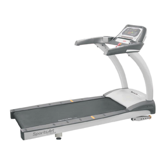
Page 4: Product Picture-T631
1-1. Product Picture-T631 1-1-1... -
Page 5: Display-T631
1-2. Display-T631 1-2-1... -
Page 6: Component Placement-T631 Display
1-3. Component Placement-T631 Display 1-3-1... - Page 7 1-3. Component Placement-T631 Display USB/CSAFE board IPOD board HTR board Bridge board 1-3-2...
-
Page 8: Component Placement-T631 Drive Board Area
1-3. Component Placement –T631 Drive Board Area 濾波器 AC 升降馬達組 SAC 伺服馬達 驅動器組 1-3-3... -
Page 9: Block Diagram-T631
1-4. Block Diagram-T631 Cardio board Polar board Polar board Display board IPOD board iPod Keypad Safety key board Bridge board HTR board Motor FUSE Filter Drive board Encoder Inductor Temperature sensor (220v) Incline motor Zero switch 1-4-1... -
Page 10: Connections-T631 Display Board
1-5. Connections-T631 Display Board To USB/CSAFE board To telemetry HR receiver To bridge board (fan) 接至驅動器組 To bridge board (safety key) To bridge board (HTR brd) To bridge board (keys) To iPod board 1-5-1... -
Page 11: Connections-T631 Bridge Board
1-5. Connections-T631 Bridge Board To display board To HTR board To safety key board 1-5-2... - Page 12 1-5. Connections-T631 Drive Board To filter To motor To incline motor To motor thermal sensor To incline zero switch To display board (signal) To display board (power) To encoder 1-5-3...
-
Page 13: Indicator Leds-T631 Display Board
1-6. Indicator LEDs-T631 Display Board Power indicator Lit indicates display has power. 1-6-1... -
Page 14: Indicator Leds-T631 Drive Board
1-6. Indicator LEDs-T631 Drive Board F1 fuse 15A Encoder indicator Condition indicator Incline up (orange) Incline down (green) Normal: flashes continuously 1-6-2... -
Page 15: Display Specifications-T631
1-7. Display Specifications-T631 Details Notes Specification 110V / 220V Exterior power SAC servo motor (with internal thermal sensor) Motor 4.0 HP Optic sensor Magnetic encoder KPH : 0.2 - 20.0(KPH) MPH : 0.1 –12.0(MPH) Speed range JAPAN:0.2-16.0(KPH) MOTOR (110V or 220V)... -
Page 16: Electronics Troubleshooting Chart-T631
2-1. Electronics Troubleshooting Chart-T631 Malfunction Circumstance Inspection and Testing Possible Part Notes Safety key Put safety key in place; there 1. Inspect display bridge board and safety key Safety key malfunction is no reaction. connections. board 2. Replace safety key. - Page 17 ERR0R_1_1_ Servo motor encoder 1. If encoder cable connection or encoder is worn, 1.Motor malfunction display directly shows ERROR 1_1. encoder 2. Replace the motor Encoder. ERR0R_1_2_ Servo motor thermal 1. Inspect the motor for excessive heat. 1.Walk belt sensor excessive heat; 2.
- Page 18 Power off Power OFF 1. Re-start unit as a test. 1.SAC drive 2. If issue reoccurs repeatedly, replace SAC drive board board. ERR0R_4_2_ Low voltage error 1. Power supply voltage is too low. 2. Inspect power supply voltage. Have power supply issue addressed immediately.
- Page 19 SERVICE NEEDED - Display shows: Every 4000 KM, this message occurs as a APPLY LUBE ”SERVICE prompt to lubricate the walk belt and deck. NEEDED - Follow instructions in the owner manual to APPLY LUBE ” lubricate the walk belt and deck. Show total distance 1.
- Page 20 Troubleshooting Model: T631 Issue: Safety key malfunction Circumstance of malfunction: Put the safety key in place. The display does not operate. Display shows “safety key”. Possible cause: Safety key board malfunction Troubleshooting: 1. Inspect the safety key magnet. 2. Inspect the bridge board cable connections.
- Page 21 Troubleshooting Model: T631 Cable connection Issue: Unit will not start operating. Circumstance of malfunction: Turn power switch on. The display does not light. Possible cause: Inadequate power supply, or component damage. Troubleshooting: 1. Inspect the main fuse and power switch.
- Page 22 Troubleshooting Model: T631 Malfunction: Soft key malfunction (display) Circumstance: Press a key on the display. There is no Soft key connector reaction. Or the key operates continually. Possible causes: 1. Soft keys are not connected. 2. Soft keys are bad.
- Page 23 Troubleshooting Model: T631 Malfunction: Soft key malfunction (display) Circumstance: Press a key on the display. There is no reaction. Or the key operates continually. Possible causes: 1.Soft keys are not connected. 2.Soft keys are bad. Troubleshooting: 1. Inspect the bridge board soft key connections.
-
Page 24: Troubleshooting
Troubleshooting Model: T631 Issue: No heart rate reading appears. Circumstance: No heart rate reading appears. Possible causes: 1. Heart rate transmitter battery power is insufficient. 2. Heart rate receiver is bad. 3. Environmental noise, such as lights and speakers, interferes with reception. - Page 25 Troubleshooting HTR Indicators Model: T631 Name Function Malfunction: Contact (Heart Touch Rate) malfunction LED1 POLAR LED Flashing indicates incoming Circumstance: Place hands on heart telemetry signal. rate contact sensors. Heart rate values LED2 HTR contact LED Lit indicates user is gripping HTR appear to be inaccurate.
- Page 26 Troubleshooting Model: T631 Malfunction: The fuse breaks at start. Circumstance: The fuse breaks as soon as power is turned on. Possible cause: 1. Components have an electrical short. 2. Drive board components are malfunctioning. Troubleshooting: 1. Remove the power cord. Test components for an electrical short.
- Page 27 Troubleshooting Model: T631 Malfunction: The fuse breaks at motor startup. Circumstance: Press the speed up key to start the motor. The fuse breaks. Possible cause: 1. The motor has an internal electrical short. 2. The drive board is malfunctioning. Troubleshooting: 1. Replace the drive board as a test.
- Page 28 Troubleshooting Model: T631 Malfunction: The fuse breaks during operation. Circumstance: After a period of use, the fuse breaks. Possible cause: 1.The fuse holder is not connected properly. 2. The walk deck or walk belt is worn. 3. The SAC drive board is malfunctioning.
- Page 29 Troubleshooting Model: T631 Malfunction: ERR0R_1_1_ Remove motor back cover. Inspect encoder board Circumstance: Press the speed key. ERR0R_1_1_ appears. Possible cause: Motor encoder malfunction Troubleshooting: 1. Inspect cable connections. 2. Inspect the encoder signal indicator. If necessary, inspect the encoder for wear.
- Page 30 Troubleshooting Model: T613 Malfunction: ERR0R_1_2 Circumstance: ERR0R_1_2 appears. Speed slows to half. Possible cause: 1. Walk deck and belt are worn. 2. Motor thermal sensor is malfunctioning, or there is a poor cable connection. Troubleshooting: 1. Inspect the thermal sensor on the motor. Low temperature: Electrically “closed”...
- Page 31 Troubleshooting Model: T613 Malfunction: ERR0R_1_3_ Circumstance: The motor does not rotate. The display shows ERR0R_1_3. Possible causes: 1. The motor is stuck or has an electrical open. Troubleshooting: 1. Re-start the unit. Does the issue reappear? 2. Inspect all cable connections. 3.
- Page 32 Troubleshooting Model: T631 Malfunction: ERR0R_2_1_, ERROR_2_2. Circumstance: Display shows ERR0R_2_1, ERROR_2_2. Possible causes: 1.SAC drive board IGBT excessive heat or excessive current Troubleshooting: 1. Re-start the unit. Test to see whether the message appears again. 2. Stop the unit for ten minutes, and test it again.
- Page 33 Troubleshooting Model: T631 Malfunction: ERR0R_2_3 Circumstance: Display shows ERR0R_2_3_. Possible cause: 1. Drive board internal circuit abnormality. Troubleshooting: 1. Re-start the unit as a test. 2. Replace the SAC drive board. Display board SAC drive board SAC drive board Motor...
- Page 34 Troubleshooting Model: T631 Incline voltage Malfunction: ERROR_3_1_ Incline Incline LED Incline cable Incline voltage Circumstance: Turn on the treadmill. The incline does not return to orange white-black 110V or 220V the 0% position. down green white-red 110V or 220V Possible cause: 1. Drive board or motor malfunction 2.
- Page 35 Troubleshooting Model: T631 Malfunction: ERROR_8_1_ Circumstance: After turning on the unit, the display shows ERROR_8-1. Possible cause: 1. Signal issue between the SAC drive board and the display program Troubleshooting: 1. After turning on the unit, the display board communicates with the drive board.
- Page 36 Troubleshooting Model: T631 Malfunction: ERROR_8_2_ Circumstance: During operation, the display shows ERROR_8_2_. Possible cause: 1. Interference of communication between the display and drive boards Troubleshooting: 1. Inspect the display-to-drive board data cable connection. 2.After the error message appears, re-start the unit. This may clear the communication issue and thereby clear the error message.
- Page 37 Troubleshooting Model: T631 Malfunction: SERVICE NEEDED-APPLY LUBE Circumstance: The message “SERVICE NEEDED-APPLY LUBE” appears, and the unit stops operating. At 4000 km of use, the lubrication service prompt “SERVICE NEEDED-APPLY LUBE” appears. Troubleshooting: 1. Insert the lube applicator tube as shown.
- Page 38 Other Instructions Model: T631 Item: Unit settings and information: KPH/MPH units, distance, time, display board program, and drive board program versions. Method: 1. Press and hold the <CHANGE> key for three seconds to enter the user setting mode. 2. Metric/imperial unit setting: Display shows “UNIT-MPH”...
- Page 39 Other Instructions Model: T631 Item: Error messages E1_1 : Servo motor encoder abnormality. Re-start the unit. E1_2 : Servo motor excessive heat warning. Motor operates at half speed. E1_3 : The motor does not rotate; the motor is stuck or has an electrical open.
- Page 40 Inspecting and Testing Model: T631 Name: Test for an electrical open on the AC servo motor Method: 1. Disconnect motor wires. Set the voltmeter to the ohm setting. Place red and black probes separately on motor wires as indicated. Normal readings:...
- Page 41 Inspecting and Testing Model: T631 Name: Incline zero point switch inspection Method: 1. Press the INCLINE<▲> or <▼> key. Inspect the incline and zero point switch operation. 2. Zero point switch operation Incline Zero switch ON (close) 1-15% OFF (open)
- Page 42 Inspecting and Testing Model: T631 Name: Incline zero point switch inspection Method: 1.Turn on power. At 0% incline, the zero switch is touched by the worm gear; The zero switch is on (electrically “closed”). At 1%-15%, the zero switch is not touched by the worm gear; The zero switch is off (electrically “open”).
- Page 43 Inspecting and Testing Model: T631 Name: Incline motor voltage test Method: 1.Set the voltmeter to the 300 VAC or higher voltage setting. 2.Press INCLINE<▲>/<▼> keys. Incline indicator LEDs on the drive board light. Measure voltage output to the incline motor. Normal readings are shown below.
- Page 44 Inspecting and Testing Model: T631 Name: Motor thermal sensor test Method: 1.When the temperature of the motor is normal, the display operates without any abnormality. Remove the motor thermal sensor cable. The display shows “SERVICE REQUIRED…” 2.When the motor has been used for a long period of time, and the display shows “SERVICE REQUIRED…”...
- Page 45 Inspecting and Testing Model: T631 Name: SAC motor encoder indicator test Method: 1.Turn on power. The display lights. The display shows “ERROR 1_1”. ERROR 1_1 usually indicates an encoder issue. 2. When the motor rotates, the drive board encoder LED flashes.
Need help?
Do you have a question about the T631 and is the answer not in the manual?
Questions and answers