
Related Manuals for SportsArt Fitness T645


Summary of Contents for SportsArt Fitness T645
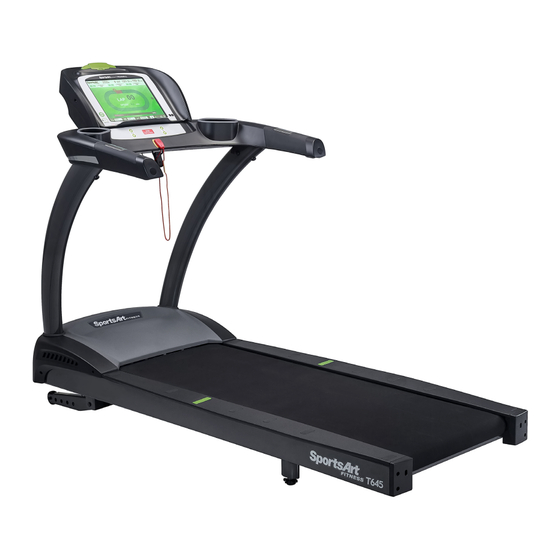
- Page 1 T645 15” TFT LCD Treadmill Owner’s Manual Sports Art Industrial Co., Ltd. ISO 9001/14001 Certified 2014.08 No. 11, Gong Huan Rd. Tainan City, Taiwan R.O.C. www.gosportsart.com...
-
Page 2: Table Of Contents
STEP 7 Install the Power Cord .............. 26 STEP 8 TV Terminal and Network ............27 STEP 9 Install the TV Cable ..............28 5. UNDERSTAND THE T645-15 DISPLAY ..........29 DISPLAY Overview ................29 DISPLAY Safety Key ................29 DISPLAY Keys .................. -
Page 3: Introduction
1. INTRODUCTION Congratulations on the purchase of a high quality SportsArt product, the T645 15” touch screen treadmill. Constructed of high quality materials and designed for years of reliable performance, this product was made for full commercial use. Before this product is assembled or operated, we recommend that you familiarize yourself with this manual. -
Page 4: Safety Precautions
2. SAfETy PRECAUTIONS This product was designed and built for optimum safety. However certain precau- tions apply during the use of this product. Please note the following safety precautions: • Please read the entire manual before assembly and operation. Make sure the product is installed and operated as instructed in this manual. - Page 5 2. SAfETy PRECAUTIONS (CONTINUED) CAUTION: If you feel any pain or any abnormal sensations, STOP YOUR WORKOUT and consult your physician immediately. Work within your recommended exercise level. DO NOT work to exhaustion. Before beginning any exercise program, you should consult with your doctor. It is recommended that you undergo a complete physical examination.
- Page 6 2. CONSIGNES DE SÉCURITÉ IMPORTANTES Votre tapis de course SportsArt a été conçu et fabriqué afin d’assurer une sécurité optimale. Cependant certaines précautions s’appliquent chaque fois que vous uti- lisez votre tapis de course. • Lisez entièrement le manuel avant l’assemblage et l’utilisation. Veuillez aussi noter les consignes de sécurité...
- Page 7 2. CONSIGNES DE SÉCURITÉ (SUITE) • Pour éviter de vous blesser, restez sur les bandes de repos (barres latérales) avant de démarrer le tapis de course. • Ce tapis de course n’est pas destiné à être utilisé par des personnes (y com- pris des enfants) dont les capacités physiques, sensorielles ou mentales sont réduites ou qui ne disposent pas de l’expérience ou du savoir nécessaires, sauf si celles-ci ont au préalable été...
-
Page 8: List Of Parts
3. LIST Of PARTS Assembly Parts No. Name Qty. No. Name Qty. Display A6a Motor right cover Handlebar assembly A6b Motor left cover Right pedestal Left pedestal Feeder cord Owner’s manual Waterproof ring Hardware kit Main frame A10 Power cord... - Page 9 Components on the Product Name Specification Notes Inner hex screw M8*L20 Spring washer Serrated washer D18*d8.5*t2 Mushroom top inner hex screw M8*L20 Serrated washer (curved) D18*d8.5*t2 Mushroom top inner hex screw M8*L20 Serrated washer D18*d8.5*t2 Mushroom top inner hex screw M5*L12 Phillips screw M4*L8...
-
Page 10: Assemble The Product
4. ASSEMBLE THE PRODUCT Follow instructions below to assemble this product. Note that in this manual the words “left” and “right” are used to refer to the product and its parts. As such, these designations correspond to the “left” and “right” sides of a person in position to exercise on this product. -
Page 11: Step 0 Preparation: Inspect The Walk Belt Placement
STEP 0 Preparation: Inspect Walk Belt Placement Inspect the position of the walk belt in relation to the guide rollers. The walk belt should be in the groove of the guide rollers (image √). Make sure that the walk belt is not outside of the groove of the guide rollers (image X). If the walk belt is in the wrong position, press the walk belt into the groove of the guide rollers. -
Page 12: Step 1 Install The Pedestals And Handlebar Assembly
STEP 1 Install the Pedestals and Handlebar assembly Follow instructions below to install the pedestals and handlebar assembly. The illustration below provides an overview of this step. (a) First, remove screws (41) from pedestal mounts. (b) Next, inspect the spring clip (A) and screw socket (B) to see if they are in place still. - Page 13 STEP 1 Install the Pedestals and Handlebar Assy (Cont.) Follow instructions (a through d) below to thread the data cable through the right pedestal. Before assembly, make sure the left & right pedestals are align with left and right sides on the main frame. (a) Pull the cable from the right side of pedestal mount.
- Page 14 STEP 1 Install the Pedestals and Handlebar Assy (Cont.) Follow instructions (a through d) below to thread the data cable through the left pedestal. Before assembly, make sure the left & right pedestals are align with left and right sides on the main frame. (a) Pull the cable from the left side of pedestal mount.
- Page 15 STEP 1 Install the Pedestals and Handlebar Assy (Cont.) While holding the data cable to prevent it from slipping into the pedestal, lift the top of the right pedestal (A3). Then insert the pedestal base onto its mount. Use screws (41) to loosely secure the right pedestal (A3) into place. Repeat the process for the left pedestal assembly.
- Page 16 STEP 1 Install the Pedestals and Handlebar Assy (Cont.) Follow the instructions (a through f) to finish install handlebar assembly. (a) Remove screws (42, 43) from the mounting plates on the bottom of the handlebar assembly (A2). (b) Securely connect the left and right cables from the handlebar assembly (A2) to the left and right pedestals (A3, A7) cables.
- Page 17 STEP 1 Install the Pedestals and Handlebar Assy (Cont.) (d) Put the previously removed screws (42, 43) back into the pedestals. Tighten the screws (42) at the B area first, then tighten the screws (43) at the C area next. (e) Finally, press the screw covers (31, 32) into the screw heads to cover them up.
- Page 18 STEP 1 Install the Pedestals and Handlebar Assy (Cont.) After securing the handlebar assembly, secure screws onto the base of left and right pedestals (area A). Put motor right and left side covers (A6a, A6b) into place, and secure them with screws (33) and then slide the water guard (A5) downward into place against the motor cover.
-
Page 19: Step 2 Install The Display
STEP 2 Install the Display Follow instructions below to install the display onto the cowling. The illustra- tion below provides an overview of this step. - Page 20 STEP 2 Install the Display (Continued) Please follow steps (a through f) to install the display. (a) First, remove screws (44) from the display mount on the handlebar as- sembly (A2). (b) Place the display (A1) onto the handlebar assembly (A2) Note: make sure the display is aligning with its guiding pieces to avoid damaging the control board.
- Page 21 STEP 2 Install the Display (Continued) (d) Connect cables in areas A, B and D. Pull the cables from handlebar as- sembly to close to display mounting plate in the area C, then connect the cables and data cables correctly and securely. Note: follow the label instruc- tions to connect the cables correctly, CATV to CATV;...
- Page 22 STEP 2 Install the Display (Continued) (e) After securing cable connections, arrange all the cables nicely, After- wards push the display (A1) slightly upward, aligning it correctly, then press it into place on the handlebar assembly. Note: make sure the cables are not pinched.
-
Page 23: Step 3 Move The Treadmill Into Place For Use
STEP 3 Move the Treadmill into Place for Use Put the hands underneath the read end of treadmill shown in area A; grasp the treadmill then lift it up, and roll the treadmill into the desired place. -
Page 24: Step 4 Level The Treadmill
STEP 4 Level the Treadmill Press downward on the rear part of the treadmill as shown. Inspect whether the treadmill rests flat on the floor. If the treadmill wobbles, adjust treadmill levelers as follows: (a) Loosen the leveler nut. (b) Rotate the leveler foot downward, touching the floor. (c) Rotate the leveler nut upward, against the frame of the product, to secure this position. -
Page 25: Step 5 Align The Walk Belt
STEP 5 Align the Walk Belt (a) First, make sure the treadmill is on a leveled surface and the incline is at (b) Start the speed at a lower rate of 3kph/2.5mph to check if the walk belt is aligned and there is an equal amount of space between walk belt and side-rails on both sides. -
Page 26: Step 6 Adjust The Walk Belt Tension
STEP 6 Adjust Walk Belt Tension Walk belt tension is important to treadmill performance. As your foot hits the walk belt, does the walk belt stop sluggishly before regaining traction? Or, if you stomp your feet, bracing against the direction of rotation, does the walk belt not pause whatsoever? When either of these two conditions occurs, walk belt tension should be adjusted. -
Page 27: Step 7 Install The Power Cord
STEP 7 Install the Power Cord First remove screws (45) from the power cord socket on the product. Insert the power cord into place on the product. Secure the power cord (A10) connector screws (45). And insert the other end of the power cord into the power socket on the wall. -
Page 28: Step 8 Tv Terminal And Network
STEP 8 TV Terminal and Netwotk (a) NETWORK: Connect to Ethernet. (b) CATV: Connect to NTSC or PAL (c) AV Terminal: Connect to DVD Player or Media Player. (d) DTV: Connect to Digital TV. -
Page 29: Step 9 Install The Tv Cable
STEP 9 Install the TV cable NTSC system: Directly connect your local area connector as shown. PAL system: Insert NTSC To PAL Adapter (30) as shown and conect to your local area connector. -
Page 30: Understand The T645-15 Display
5. UNDERSTAND THE T645-15 DISPLAy DISPLAy Overview The T645-15 display was designed to help people obtain their fitness goals simply and conveniently. Please familiarize yourself with the features of this display and thereby get optimum benefit and enjoyment from this product. -
Page 31: Display Keys
DISPLAy Keys 1. Energy Smart wake up button 2. Headphone Jacks 3. Stop/Reset button 4. Speed Up/Down keys 5. Incline Up/Down keys DISPLAy Windows SPEED (forward rotation): 0.2 to 20.0 kph; 0.1 to 12.0 mph INCLINE: 0% to 15%, in intervals of 0.5% TIME: 0:00 to 600:00 DISTANCE: 0.00 to 9999 kilometers or miles CALORIES: Range 0 to 9999 kcal... -
Page 32: Display Home Page
4. USER PROFILE key: to set up user’s profile 5. DEFAULT SETTINGS key: to enter engineering settings 6. HELP key: to find out information and/or instruction for each function 7. GO GREEN key: to learn more about SportsArt Fitness’ Green Mission... -
Page 33: Operate The T645-15 Treadmill
6. OPERATE THE T645-15 TREADMILL There are two ways to start operating this product: (1) Press the QUICK START key, or (2) press the PROGRAM SELECTION key to enter a preset program. Using the QUICK START key allows you to begin exercising im- mediately, without first entering user information. - Page 34 OPERATION Quick Start (Continued) 8. Left-handed or right-handed buttons: press either hand to put the Quick keys (10) on the left side of the screen or right side. 9. Home button and Back button: when these buttons are light up, press home button to go back to home page or press Back button to go back to previous page.
-
Page 35: Operation Program Selection
OPERATION Quick Start (Continued) Workout summary: OPERATION Program Selection The program mode provides user-specific caloric expenditure and target heart rate values, along with accumulated time, total distance, and total ca- loric expenditure values for individual users. WORKOUT PROGRAMS: Preset workout programs include: Track, Glute, Hill (Hill 1, Hill 2, Hill 3), Ran- dom, Interval (1:1, 1:2, 2:2) programs. - Page 36 OPERATION Program Selection (Continued) HILL Hill is a preset incline profile program; there are 3 profiles to select from. Once Hill program is selected, it will enter user profile setting page. The pro- gram setting is the same as Track program setting, please refer to previous page for details.
- Page 37 OPERATION Program Selection (Continued) Display during exercise is the same as Hill program, refer to Hill program page for details. GLUTE The Glute Program exercises the gluteus muscle group of the body. There are 2 different exercise illustrations built into this program: 30 minute and 45 minute programs.
- Page 38 OPERATION Program Selection (Continued) RANDOM Each time the RANDOM key is pressed a different randomly generated workout illustration will appear. There is an almost infinite number of ran- domly generated workouts. Once Random program is selected, it will enter user profile setting page: Age, weight, goal and speed. After setting, press START to begin the program.
-
Page 39: Operation Heart Rate Programs
OPERATION Program Selection (Continued) Display during exercise is shown below. The red flag is the start position as well as the end position. The tear drop shape represents the current position and it runs in a clockwise direction. HEART RATE PROGRAM A heart rate program is a goal program based on the target heart rate. - Page 40 OPERATION Program Selection (Continued) (1) Target Heart Rate 65% & 80% The target heart rate is calculated at the 65% or 80% of the max heart rate with the max heart rate equals (220 - age). Once one of these program is selected, it will enter user profile setting page: Age, weight, time, priority and max speed.
- Page 41 OPERATION Program Selection (Continued) (2) Custom Heart Rate In Custom heart rate program, user gets to set his/her own heart rate target. Once Custom heart rate program is selected, it will enter user profile setting page: Age, weight, time, target heart rate, priority and max speed. When the Incline is as the control method, user may adjust the speed during program.
-
Page 42: Operation Fit Test Programs
OPERATION Program Selection (Continued) fIT TEST PROGRAMS The FIT TEST program includes 11 preset types of physical fitness assess- ments: Bruce, Gerkin, WFI (the Wellness Fitness Initiative), Army, Marines, Navy, Air Force, and PEB (Physical Efficiency Battery), British Fireman, Nor- way Fireman, Sweden Fireman as well as a Custom Fit Test program. - Page 43 OPERATION Program Selection (Continued) (1) Bruce This program is designed based on Bruce Protocol for examining one’s car- diac function. Health care professional often uses this test along with elec- trocardiogram to assess one’s cardio health. When using this program, user may stop the test at anytime according to his/her condition.
- Page 44 OPERATION Program Selection (Continued) The ARMY and MARINES tests will begin after the gender setting. But the Navy test offers more options from which to choose. The NAVY test includes five different physical fitness assessments: 1-IFA (Individual Fitness Assess- ment), 2-SEAL (Sea Air Land), 3-SBO (Swift Boat Operator), 4-EOD (Ex- plosive Ordnance Disposal), 5-ARS (Air Rescue Swimmers).
- Page 45 OPERATION Program Selection (Continued) (8) Norway fireman If the test is completed, “TEST FINISH” will appear. It will return to home screen in 2 minute if no other activities occurred. If the test is interrupted and not finished, “TEST FAIL” will appear. It will return to home screen in 2 minutes if no other activities occurred.
-
Page 46: Operation Media Selection
OPERATION Media Selection There are several media input options built in this console; such as TV(TV, DTV, A/V), YouTube, Hulu, Netflix, iPod/iPhone, USB(Music/Video), Face- book, Twitter social medias. There is a built in remote control for changing the channels and volume con- trol. -
Page 47: Operation User Profile
OPERATION User Profile User profile is designed for more accurate workout calculation and control during program. It is encouraged to enter and save the user profile before each program for future convenience and more accurate workout tracking. User may build his/her own program by press Custom Program button and define all the segments. -
Page 48: Operation Default Setting
OPERATION Default Setting User may change the default setting by visit Default setting section and mod- ify the settings. (1) Language Setting: user may select a different language by choosing an associated country. (2) Engineering Setting: this section is designed for service provider or equipment manager to access the product’s record as well reviewing the his- tory of this product. - Page 49 OPERATION Error Messages Error messages can appear on this treadmill as a troubleshooting aid. Error messages appear in the following format: “ERROR _X_Y”. X represents the category of the error. Y represents the specific issue. In the position of the X placeholder, the following numbers can appear to represent the category of the malfunction: Code Explanation...
-
Page 50: Operation Switching Program
OPERATION Switching Program User may switch to a different program during exercising by pressing the Program Selection button on the bottom of the screen. If this occurs, the program goal will remain the same as previous program and data accumula- tion (Time, Distance, Calories) will continue counting from previous program as well. -
Page 51: About Heart Rate Detection
7. ABOUT HEART RATE DETECTION Heart rate detection functions are selected at the time of purchase. Not every product includes every type of heart rate detection device. The following explains factors that influence the performance of two of the most common types of heart rate detection devices. -
Page 52: Guidelines For Exercise
CAUTION: Heart rate detection and transmission devices have been known to interfere with the operation of pacemakers, possibly endangering human life. If you have a pacemaker, exercise under your doctor’s supervision; take a test to ensure your safety during the simultaneous use of the pacemaker and heart rate detection devices. -
Page 53: Accessories
9. ACCESSORIES There are accessories attached to this console; some are standard and some are optional. The following explains the details of each accessory and its function. USB CHARGER (Standard) The USB charger will provide 5V 500mA voltage for the smart phone or other devices charging. -
Page 54: Accessories Entertainment Cap
9. ACCESSORIES (CONTINUED) Entertainment Cap (a) RFID member card slot: work with both optional SA WELL+ and ECOFIT member cards. (b) Bluetooth connection button: press this button to unpair the smart phone SA WELL+ App. (c) USB port: this port is used for device charging as well as optional data transferring. -
Page 55: Maintenance
10. MAINTENANCE This section covers maintenance topics, including instructions on replacing a fuse and lubricating the walk belt, along with the presentation of a main- tenance schedule, maintenance task list, one-year maintenance log, and electronics block diagram. MAINTENANCE How to Replace a fuse If electrical current becomes too high, the fuse breaks. -
Page 56: Maintenance Lubrication System
MAINTENANCE Lubrication System Lubrication System flowchart Model No. Display ex: T655 Total Exercise 5 seconds Distance Display (km) Power On RESET Walks Belt Version Display Total Exercise Total Exercise Total Exercise Speed Total ex:T655 Distance Display (mile) Distance Display (km) Distance Display (km) Running Time... - Page 57 MAINTENANCE Lubrication System (Continued) To replace the lubricant bottle, follow instructions (a) through (d) below. (a) Loosen the screws on the bezel and push the bezel up. (b) Take the old lubricant bottle out. (c) Unscrew the nozzle from the old lubricant bottle and screw it onto new bottle.
- Page 58 MAINTENANCE Lubrication System (Continued) Error Messages: There are 2 error messages with this system. Error 1: It indicates that the system memory failing and it will not be able to perform any auto lubrication. Error 2: It indicates motor is failing or system will not be able to perform any function.
-
Page 59: Maintenance Schedule
MAINTENANCE Schedule Area Day Week Month Quarter Year Notes Exterior Clean. Screws Inspect and secure loose parts. Ensure the treadmill operates properly. Treadmill test Inspect alignment (centering) and look Walk belt for wear. Walk deck Inspect for wear. Belt guides Inspect for normal rotation. -
Page 60: Maintenance Task List
MAINTENANCE Task List Like cars, fitness products require maintenance. Regular maintenance ex- tends product life, and failure to maintain products can void the manufac- turer’s warranty. Copy the maintenance log sheet, and record maintenance work for each fitness product. Daily tasks 1. -
Page 61: Maintenance One-Year Maintenance Log
MAINTENANCE One-year Maintenance Log Facility:_______________________ Supervisor:____________________ Product model number:__________ Serial number:_________________ Start date: ____________________ End date:_____________________ Daily Tasks Weeks 1-7 Weeks 8-14 Weeks 15-21 Week 22-28 Completed Daily Tasks Week 29-35 Week 36-42 Week 43-49 Week 50-52 Completed Weekly Tasks Weeks 1-7 Weeks 8-14 Weeks 15-21 Weeks 22-28... -
Page 62: Maintenance Electronics Block Diagram
MAINTENANCE Electronics Block Diagram USB Board HRC Board 15" LCD Screen Control Board HTR Board Display Board EUP Key Board CSAFE Board CATV IPOD Board Head Phone Board Contact HTR plates Bridge Board :Connector Safety key Board :Converge [Option] Speed/Incline Key Board Fan Board Drive Board Incline Control Motor...
Need help?
Do you have a question about the T645 and is the answer not in the manual?
Questions and answers