Table of Contents
Advertisement
Advertisement
Table of Contents

Related Manuals for SportsArt Fitness T652M


Summary of Contents for SportsArt Fitness T652M
- Page 1 T652M/T652MD Instruction Manual...
-
Page 2: Table Of Contents
5. T652M DISPLAY..................... Display Features....................Display Functions....................Button Functions....................Safety Key......................Workout Time Limit Setting..................6. HOW TO USE YOUR T652M TREADMILL............Quick Start......................Workout Setup......................Operating Procedure during Exercise..............Cool Down......................7. ABOUT THE HEART RATE DETECTION AND PRESENTATION...... -
Page 3: Introduction
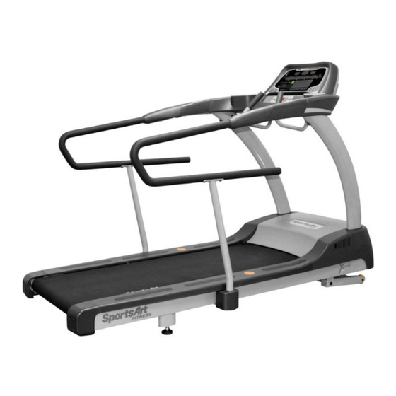
Congratulations on the purchase of one of the finest pieces of commercial exercise equipment on the market today, the SportsArt T652M Commercial Treadmill. The T652M is designed with the end-user in mind and constructed of high quality materials for years of trouble-free use. -
Page 9: List Of Parts
LIST OF PARTS Assembly Parts Number Qty Number Name Name Display Owner manual Handlebar assembly Hardware kit Power cord Safety key Right pedestal Applicator tube Silicone lubricant Feeder cord Upper and lower left and Waterproof ring right connector covers Main frame Right side cover Left and right long handrails Left side cover... - Page 10 Hardware Kit Name Specification Number Notes Screw cover (flat) Screw cover (rounded) 15A-100V~110V Fuse 10A-200V-240V L-shaped Allen wrench (M4) L-shaped Allen wrench (M5) L-shaped Allen wrench (M6) L-shaped Allen wrench (M6) Double open-end wrench (22*24) Screwdriver handle green Screwdriver bit Phillips and flat Components on the Product Number...
- Page 11 Please make sure that the walk belt runs below the walk belt guides. Walk belt guides should press the walk belt down on both sides. If the walk belt is on top of the guides, loosen screws at position A. Place the walk belt below the guides as shown. Then readjust walk belt tightness per instructions in part 6.
-
Page 12: Treadmill Assembly
TREADMILL ASSEMBLY STEP 1 Assemble the Left and Right Pedestals and Handlebars... - Page 13 1-1. Remove pedestal mount covers (A6a,A6b). 1-2. Remove screws (41) from the pedestal mount as shown.
- Page 14 1-3. Follow steps (a~e) in order to thread the data cable into the right pedestal. (a) First, remove the zip tie on the cable in the right pedestal mount. Then stretch the cable out as shown. (b) Place the right pedestal (A3) on the floor, with the lower hole facing the data cable.
- Page 15 1-4. Hold the data cable at the top of the right pedestal (A3), and insert the bottom of the pedestal onto the pedestal mount. Avoid pinching or crimping the data cable. Place the water guard (A6) on the pedestal higher than the motor cover. Loosely secure the right pedestal (A3) with screws (42).
- Page 16 1-5. Follow steps (a~e) to install handlebars. a. First, remove the screws (42, 43) from the handlebar assembly (A2). b. Insert the left side of the handlebar (A2) into the left pedestal (A7). c. Connect the cables in area A from the right pedestal (A3) and from the handlebar (A2).
- Page 17 d. Tuck cables into the pedestal safely. Then insert the right side of the handlebar assembly (A2) into the right pedestal (A3), without pinching or crimping cables. e. Thread screws in place by hand. First, secure screws (42) in area B. Then secure screws (43) in area C.
- Page 18 1-6. After the handlebars are in place, secure pedestal screws on left and right sides. Put pedestal covers (A6a,A6b) in place. Then put water guards (A5) down against the motor cover on both sides.
-
Page 19: Step 2 Install The Display
STEP 2 Install the Display... - Page 20 2-1. Follow steps (a~g) below to install the display assembly. a. Remove screws (44) from the handlebar (A2). b. Insert the display (A1) onto the handlebar assembly (A2). Note: aim properly to avoid damaging the display board. c. Then slightly lift the display (A1). d.
- Page 21 e. Connect cables in areas A and B. f. After connecting cables, tuck them away for safety. Then slightly lift the display (A1) and press it into place. Note: In area C, the display cover must be outside of the handlebar cover. g.
-
Page 22: Step 3 Install Long Handrails
STEP 3 Install Long Handrails... - Page 23 3-1. First, remove the sticker, screws, and end cap from the left and right handlebars. Also, remove the two middle anti-slip strips from the landing strips.
- Page 24 3-2. First, detach upper and lower connector covers from the left and right handrails. Then remove the screws from the lower part of the handrails.
- Page 25 3-3. First, set the long handrail supports into the frame. Then loosely secure them with screws. Do not tighten the screws yet.
- Page 26 3-4. Set left and right long handrails in place on the handrail supports as shown. Use screws (a,b) to secure the long handrails to the handle ends.
- Page 27 3-5. Install upper and lower connection covers onto the long handrails. To do so, first slide the covers toward the front. Then secure the cover screws. 3-6. Secure left and right long handrail support screws. Then press the anti-slip strip into place.
-
Page 28: Step 4 How To Move The Treadmill
STEP 4 How to Move the Treadmill 4-1. First, place hands under the frame in area A, lift the treadmill, then roll it into position as desired. -
Page 29: Step 5 Level The Unit
STEP 5 Level the Unit 5-1. Press on points A and B to inspect whether the unit is stable and level on the ground. 5-2. If not, please level the treadmill by following instructions (a, b, c): a. First, loosen leveler nuts. b. -
Page 30: Step 6 Align The Walk Belt
STEP 6 Align the Walk Belt 6-1. The walk belt should run in the center of the deck, with an even amount of space on both sides, between the belt edges and the landing strips. If the space on either side is not the same, rotate rear roller screws about one-half turn at a time. -
Page 31: Step 7 Adjust Walk Belt Tightness
STEP 7 Adjust Walk Belt Tightness 7-1. As you exercise, does the walk belt suddenly pause and then regain traction? Or, if you bear down against the walk belt, does the belt not pause whatsoever? If either of these two conditions occur, the walk belt may be too loose or too tight. In this case, please turn off the treadmill and adjust walk belt tightness. -
Page 32: Step 8 Install The Power Cord
STEP 8 Install the Power Cord 8-1. First remove screws (45) from the power cord socket on the product. 8-2. Insert the power cord into place on the product. 8-3. Secure power cord connector screws (45). Then insert the other end of the power cord into the appropriate power supply socket in the wall. -
Page 33: Step9 Replacing The Fuse
STEP9 Replacing the Fuse If current becomes too high, the fuse breaks. This protects the product. To replace a fuse, follow instructions (a~g) below. (a) Press inward on the fuse cap. (b) Turn the fuse cap counterclockwise. (c) The fuse and fuse cap springs out. (d) Remove the burnt fuse. -
Page 34: T652M Display
T652M DISPLAY A. Display Features Please make corrections indicated: Wt Loss Training Cardio Advisor Cardio Training Feedback Window Heart Rate LED Programs Numeric Keypad Dot Matrix Display B. Display Functions 1. SPEED: 0.1 to 12.0 MPH or 0.2 20.0 KPH in 0.1 increments SPEED: -0.1 to -3.0 MPH or -0.2 to -5.0 KPH in 0.1 increments... -
Page 35: Button Functions
7. CAL/Hr: Calories burnt per hour, 0 to 9999 KCAL 8. METS (Metabolic Equivalent of Task): 0.0 to 99.0 9. PACE: 1/SPEED 10. PROGRAM: MANUAL/REVERSE, HILL (HILL1, HILL2, HILL3), RANDOM INTERVAL (1:1, 1:2, 2:2), TRACK, GLUTE, FAT BURN, ZONE TRAINER, 。... - Page 36 10. WT LOSS/CARDIO Press to start the heart rate control modes - Wt Loss & Cardio. The weight loss program keeps the user's heart rate at 65% of maximum (i.e. (220-AGE)*0.65) to provide an optimal weight loss workout, while the cardio program keeps the user's heart rate at 80% of maximum (i.e.
-
Page 37: Safety Key
D. Safety Key 1. Before exercising, set the magnetic side of the safety key into its slot on the treadmill. Clip the other side of the safety key cord onto your clothes. 2. The safety key must be in place for the treadmill to operate. This safety device is intended to stop the treadmill should a user stumble and fall. -
Page 38: How To Use Your T652M Treadmill
HOW TO USE YOUR T652M TREADMILL 1. Quick Start Press QUICK START to start exercising without first inputting user information. "TREAD STARTING" will appear on the display, and the walk belt will rotate at 0.1 MPH/0.2 KPH. Press SPEED up/down to change speed. The user default setting is 165 LB/75 KG. - Page 39 (5) When "TRACK" is selected, the 14-segment display will show "TRACK". Press → → → more times to view TRACK TRACK 5K TRACK 10K ... In "TRACK", press ENTER to confirm your choice. If you selected TRACK 5K or TRACK 10K, the exercise course begins immediately.
-
Page 40: Operating Procedure During Exercise
3. Operating Procedure during Exercise A. Press QUICK START or press START and follow prompts to input user information. The 14-segment display will show "TREAD STARTING". Meanwhile, the dot matrix display will show a countdown "3 2 1", and then the AC servo motor will start operating. -
Page 41: About The Heart Rate Detection And Presentation
ABOUT THE HEART RATE DETECTION AND PRESENTATION About Telemetry Heart Rate The word "telemetry heart rate" refers to the detection of the heart rate, usually via a strap worn on the exerciser's chest, and transmitted over the air for reception by a receiver built into the product. - Page 42 4. The vibration of treadmills at speeds over 4 MPH/6.4 KPH makes heart rate detection difficult. Also, if your hands move, heart rate detection becomes difficult. Suggestions: For better heart rate detection, keep hands in one place on the contact plates. Or wear a telemetry heart rate strap on your chest.
-
Page 43: Program Details
PROGRAM DETAILS 1. MANUAL/REVERSE & TRACK Walk belt rotates for the user to walk or run in the forward direction (0.1MPH ~ MANUAL 12.0MPH)/(0.2KPH 20.0KPH) ~ Walk belt rotates for the user to walk in the backward direction (-0.1MPH ~ REVERSE -3.0MPH)/(-0.2KPH -5.0KPH) ~... - Page 44 A. Target heart rates: × (1) WT LOSS = 65% Heart Rate Control: (220 - AGE) × (2) CARDIO = 80% Heart Rate Control: (220 - AGE) B. HRC (Heart Rate Control) mode: Before starting to exercise, select the maximum speed. The 14-segment display ▲...
- Page 45 、 、 、 、 、 、 、 、 、 、…… Stage10 : 3 4 6 8 10 3 3 5 7 9 、 、 、 、 、 、 、 、…… Stage11 : 4 5 6 7 8 11 9 10 、...
-
Page 46: Guidelines For Exercise
GUIDELINES FOR EXERCISE How hard should I exercise? Studies show that to achieve the benefits of aerobic exercise, it is necessary to work within your training zone. Your training zone depends on your age and level of fitness. The above chart indicates the recommended Heart Rate training zones (darkened area of the chart). -
Page 47: User Parameter Setting
USER PARAMETER SETTINGS User parameters determine basic operating features, such as distance units, of the treadmill. To change these parameters, at the banner display, hold the CHANGE DISPLAY button for three seconds. 1. Set up MPH/KPH. The 14-segment display will show the current status as either <... -
Page 48: Maintenance
MAINTENANCE Periodic maintenance is crucial to the performance of fitness equipment, just like it is to the performance of an automobile. The better you maintain a product, the longer it will serve your needs. This treadmill requires periodic lubrication of the walk belt and has a built-in system to prevent overuse without maintenance. - Page 49 1. Remove one treadmill end cap. ▲ ▼ 2. Simultaneously press and hold INCLINE + INCLINE + 0 keys for two seconds. The treadmill will operate at low speed. At this point, no UP or DN keys will operate. 3. Insert the applicator tube so the line on the applicator touches the side of the walk belt.
- Page 50 6. Remove the applicator and the bottle of lubricant. 7. Secure the end cap on the treadmill. 8. Then the message "PLEASE PRESS THE STOP KEY AFTER FINISHING LUBRICATION" appears. Press the STOP key to complete the lubrication procedure. The treadmill will recalculate the total distance and operate normally.
- Page 51 Lubricating When Not Prompted The physical task of lubricating the treadmill can be done at any time. When the startup ▲ banner, SPORTSART-T652M, is displayed, simultaneously press and hold INCLINE ▼ + INCLINE + 0 for two seconds. The motor will operate at low speed at which time you can apply lubricant to the walk belt.
-
Page 52: Maintenance Checklist
MAINTENANCE CHECKLIST Like cars, fitness products require maintenance. Regular maintenance extends the life of your fitness product, and failure to provide regular maintenance will void your warranty. Copy the maintenance log sheet and record maintenance work. Daily tasks 1. Check the product, including the safety key, for safe operation. Secure any loose screws. - Page 53 4. Clean and lubricate walk deck bushings. For lubrication of deck bushings, use red lithium grease. Remove bushing lubricant that touches the walk belt or deck surface. General Notes on Maintenance Note that product maintenance requirements depend on usage and environment. This schedule is based on average use.
- Page 54 One-Year Maintenance Log for Treadmills Facility Name: Maintenance Supervisor: Product serial number: Start Date: End Date: Daily Tasks Week1 Week2 Week3 Week4 1.Safe 2.Clean Daily Tasks Week5 Week6 Week7 Week8 1.Safe 2.Clean Daily Tasks Week9 Week10 Week11 Week12 1.Safe 2.Clean Monthly Tasks Months 1-3 Months 4-6...
-
Page 55: Error Messages
ERROR MESSAGES 1. Display format: 2. Explanations for each error message: ERROR_1_1_ The AC servo motor encoder is out of order. Please re-start the unit. ERROR_1_2_ The AC servo motor is overheated. Speed is restricted to half. ERROR_1_3_ The AC servo motor is overloaded. Please re-start the unit. ERROR_2_1_ The IGBT current is too high. -
Page 56: Wiring Schematic
WIRING SCHEMATIC: Board CON2 CON4 CON1 CON3 CON7 *Option CON5 iPod decoder Board T652M CTL Board CON3 USB CHARGER BOARD CON6 CON2 DRV Board PWR Board DSP Board Encoder Incline SERVO Bridge Board MOTOR Switch CN10 CN2 CN3 HTR Board...
Need help?
Do you have a question about the T652M and is the answer not in the manual?
Questions and answers