Baroness LM180C Owner's Operating Manual
Super mower
Hide thumbs
Also See for LM180C:
- Owner's manual (61 pages) ,
- Owner's operating manual (56 pages) ,
- Owner's operating manual (66 pages)

Subscribe to Our Youtube Channel
Related Manuals for Baroness LM180C


Summary of Contents for Baroness LM180C
- Page 1 Super Mower Owner's operating manual "Required reading" Read this manual and the owner's manual for the engine before using the machine. Serial No.20001- Original Instructions Ver.1.2...
- Page 2 LM180C Greeting Thank you for purchasing the Baroness machine. This manual explains proper handling, adjustment, and inspection of your machine. Prior to use, carefully read this manual to thoroughly understand the contents for safe and correct operation. We hope you will use the machine safely, and take advantage of its best performance.
- Page 3 The information described in this manual is subject to change for improvement without prior notice. When replacing parts, be sure to use genuine Baroness parts or parts designated by Kyoeisha. Note that the Baroness product warranty may not apply to defects caused by the use of parts from other companies.
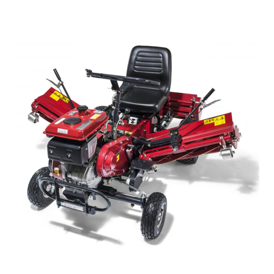
- Page 4 LM180C Introduction Purpose This machine is intended for cutting turf grass at golf courses. Do not use this machine in any way other than its intended purpose, and do not modify the machine. Operating this machine for other purposes and modifying it may be very dangerous and may cause damage to the machine.
-
Page 5: Table Of Contents
LM180C Contents Safety............... Page 1-1 Safe Operating Practices........Page 1-2 Disposal............Page 2-1 Waste disposal..........Page 2-2 Product Overview........... Page 3-1 Specifications..........Page 3-2 Names of Each Section........Page 3-3 Safety Signs and Instruction Signs....Page 3-4 Handling Instructions........Page 4-1 Inspection Before Use........Page 4-2 Tightening torques.......... - Page 6 LM180C Contents...
-
Page 7: Safety
LM180C Safety Safe Operating Practices....... Page 1-2 Training...........Page 1-2 Preparation..........Page 1-2 Operation..........Page 1-3 Maintenance and storage....... Page 1-4 Page 1-1... -
Page 8: Safe Operating Practices
LM180C Safety Failure to adequately follow these safety Lack of awareness of the effect of precautions may cause an accident resulting in ground conditions, especially slopes injury or death. Incorrect hitching and load distribution Never allow untrained personnel to service... - Page 9 LM180C Safety Replace all fuel tanks and container caps Do not change the engine governor settings securely. or overspeed the engine. Operating the engine at excessive speed may increase the Check that operator’s presence controls, hazard of personal injury. safety switches and shields are attached and functioning properly.
- Page 10 LM180C Safety Take care when loading or unloading the Never allow untrained personnel to service machine into a trailer or a truck. Load or machine. unload the machine in a flat and safe place. Allow the engine/muffler to cool before Before loading or unloading, set the parking checking/maintenance.
-
Page 11: Disposal
LM180C Disposal Waste disposal........Page 2-2 About the Waste disposal....... Page 2-2 Page 2-1... -
Page 12: Waste Disposal
LM180C Disposal Waste disposal About the Waste disposal Make sure that waste generated when servicing or repairing the machine is disposed of in accordance with local regulations. (e.g. waste oil, antifreeze batteries, rubber products, and wires etc.) Page 2-2 Waste disposal... -
Page 13: Product Overview
LM180C Product Overview Specifications......... Page 3-2 Specifications..........Page 3-2 Sound pressure level......Page 3-2 Sound power level........Page 3-2 Vibration level......... Page 3-3 Names of Each Section......Page 3-3 Serial Number Plate........Page 3-3 Specification Decal......... Page 3-3 Noise Emission Decal......Page 3-4 Year of Manufacture Decal..... -
Page 14: Specifications
LM180C Product Overview Specifications Specifications Type LM180C Total length 215 cm During 208 cm operation Total width Dimensions During 185 cm transport Seat 107 cm Total height Steering wheel 102 cm Weight 387 kg Minimum turning radius 230 cm Type... -
Page 15: Names Of Each Section
LM180C Product Overview Vibration level Steering wheel Traveling clutch lever Hand-arm vibration Change lever This machine was confirmed to transmit a Parking brake lever maximum vibration level of 3.63 m/s to hands Left mower unit and arms by measuring identical machines in... -
Page 16: Safety Signs And Instruction Signs
Product Overview Part numbers for decals that need to be Noise Emission Decal replaced are listed in the parts catalog. Order them from a Baroness dealer or The noise emission decal indicates the sound Kyoeisha. power level determined by measuring identical... -
Page 17: Explanation About Safety Decals And Instruction Decals
LM180C Product Overview Explanation about Safety Decals and Instruction Decals LM180C-1001Z0 Sticker, operation Warning Read the manual. Danger Danger Flying objects - All persons other than the operator must keep a safe distance from the machine. Danger Danger qigqnx-009 Rollover - Do not work on slopes of 18 degrees or more. - Page 18 LM180C Product Overview Stay clear of the hot surface. Check for leakage from hose and fittings. CHECK FOR LEAKAGE FROM HOSES AND FITTINGS. SHUT OFF FUEL VALVE WHEN ENGINE IS NOT IN USE. qigqnx-013 R073-20046-40 Decal, engine alert Spark plug cover must be in place when refueling.
-
Page 19: Handling Instructions
LM180C Handling Instructions Inspection Before Use......Page 4-2 Cutting Work......... Page 4-14 Reel Cutter (Cutting Cylinder) and Cutting Operation......... Page 4-14 Bed Knife (Bottom Blade)....... Page 4-2 Transporting..........Page 4-14 Air cleaner..........Page 4-2 Tire............Page 4-3 Transporting Procedure......Page 4-14 Brake............Page 4-3 Belt............Page 4-3... -
Page 20: Inspection Before Use
LM180C Handling Instructions Air cleaner Inspection Before Use Inspection of Air Cleaner Be sure to perform an inspection before you start using the machine so that you will be able to take For details on handling the engine, please refer advantage of its optimum performance for a long to the separate Engine Handling Manual. -
Page 21: Tire
LM180C Handling Instructions Follow the steps below to clean the air Belt cleaner. Inspection of Belts Before installing the element, clean it with white kerosene, immerse it in an admixture of three parts white kerosene Caution to one part engine oil, and then shake/ If you have removed the shield during squeeze it. - Page 22 LM180C Handling Instructions The appropriate oil level should be between Change of Engine Oil the two knurl lines on the gauge. For details on handling the engine, please refer to the separate Engine Operating Manual. Warning When you change the engine oil, be sure to...
-
Page 23: Transmission
LM180C Handling Instructions Install the oil gauge. Through the oil filling port, fill the transmission oil. Check the oil level again 10 to 20 minutes after filling the oil. gui678-004 Change of Engine Oil_001 Oil filling port / oil gauge... -
Page 24: Fuel
LM180C Handling Instructions Make sure that the transmission oil level is Warning filled up to the tip of the oil level opening. Keep fire away while refueling. Attach the oil filling port cap and oil level Do not smoke while refueling. -
Page 25: Tightening Torques
LM180C Handling Instructions Tightening torques Standard tightening torques Bolts and screws Unless otherwise instructed, tighten bolts or nuts by the specified torque using an appropriate tool. Excessive tightening of a screw may cause it to become loose or damaged. The appropriate tightening torque depends on factors such as the type of screw, its strength, and the friction of its thread and bearing surface. -
Page 26: Principal Tightening Torques
LM180C Handling Instructions Heat-treated screws Strength category: 8.8 Strength category: 10.9 Nominal diameter 10.9 tib3yb-002 tib3yb-003 kgf-cm lb-in kgf-cm lb-in 5 - 7 50.99 - 71.38 44.26 - 61.96 7 - 10 71.38 - 101.97 61.96 - 88.51 8 - 11 81.58 - 112.17... -
Page 27: Adjustment Before Operating
LM180C Handling Instructions Tightening Torque Thread locking Portion Code Part name adhesive kgf-cm lb-in Bed knife Screw, heat-treated flathead 295.71 - 256.68 - K0071000092 29 - 38 - (Bottom blade) M10-20 387.49 336.34 591.43 - 513.36 - Front roller K0010100252 Bolt, heat-treated M10-25 58 - 76 -... -
Page 28: Procedure To Start / Stop Engine
LM180C Handling Instructions If the blades still cannot cut well: To decrease cutting height: Perform lapping of the reel cutter (cutting Loosen nut B, raise the roller, then tighten cylinder). nut A. 2f8equ-001 3kws2a-002 Adjustment of Blade Engagement_001 Adjustment of Cutting Height_001... -
Page 29: Operation Of Each Section
LM180C Handling Instructions Shift the throttle lever to "Low", and then Diff-lock pedal warm up the engine for 1 to 2 minutes. Brake pedal Gradually move the throttle lever to "High". Traveling clutch lever Procedure to Stop Engine Traveling clutch "OFF"... -
Page 30: Operation Of Change Lever
LM180C Handling Instructions To lower the left and right mower units, To lower the rear mower unit, squeeze the squeeze the clutch lever and slowly move the clutch lever and slowly move the lifting lever lifting lever down. down. 5zujec-001... -
Page 31: Traveling Clutch Lever
LM180C Handling Instructions The change lever is a transmission device. Operation of Reel Rotation Lever It was adapted from a direct change system. To change the speed, park the machine on level Caution ground, and then engage the lever in the desired position. -
Page 32: Travel Of Machine
LM180C Handling Instructions To park the machine, pull the parking brake Caution lever completely. To release the parking brake, press the push Cutting work must be performed at an button while lowering the parking brake lever all appropriate speed for the site and location. -
Page 33: Maintenance
LM180C Maintenance Maintenance Precautions...... Page 5-2 Maintenance Schedule......Page 5-2 Specified Values........Page 5-4 Main Consumable Parts......Page 5-4 Jacking up the machine......Page 5-4 About the Jacking up the machine..Page 5-4 Jack-up Portion........Page 5-5 Greasing..........Page 5-6 About the Lubrication......Page 5-6 Greasing Points........ -
Page 34: Maintenance Precautions
Use tools appropriate for each maintenance operation. Caution For the safe and best performance of your machine, use Baroness genuine parts for replacement and accessories. Please note that our product warranty may be void if you use non-genuine parts for replacement or accessories. - Page 35 LM180C Maintenance Maintenance Item Tightening the parts ○ Interlock system ○ Emergency switch ○ Electrical wiring ○ Knife ○ Steering chain ○ Cutting (or brush) height ○ Greasing, oiling ○ Tire ○ Rubber crawler ○ V-belt ○ △ Brake ○...
-
Page 36: Jacking Up The Machine
LM180C Maintenance Specified Values Fuel tank capacity 6.0 dm (6.0 L) Quantity of transmission oil 2.0 dm Transmission gear oil #90 (2.0 L) Quantity of engine oil Summer: SAE30, Winter: SAE20 1.2 dm (1.2 L) Front tire 4.00 - 5 200 kPa(2.0 kgf/㎝... -
Page 37: Maintenance (Mower)
LM180C Maintenance Front axle, right Jack-up Portion rwyt62-013 Jack-up Portion_003 Front axle, left rwyt62-014 rwyt62-011 Jack-up Portion_004 Transmission case, lower Jack-up Portion_001 Jack-up Portion Front axle, center Front axle, right Front axle, left Transmission case, lower Transmission axle case, left... -
Page 38: Greasing
LM180C Maintenance Transmission axle case, right No. of Portion Greasing Points Front wheels Front wheel front pin Reel housing Mower frame Mower lifting arm Diff-lock pedal Handle tension rwyt62-017 Brake pedal Jack-up Portion_007 Rear mower oscillating metal part Greasing Rear roller... - Page 39 LM180C Maintenance Reel housing Diff-lock pedal There is one point each on the left and the right of each unit. 8bq62b-061 Greasing Point_007 Handle tension 8bq62b-058 Supply automobile transmission gear oil #90 Greasing Point_004 Mower frame every 50 hours of operation.
-
Page 40: Lapping Of Reel Cutter (Cutting Cylinder)
Do not perform lapping with any other persons. Have the following items ready: Lapping machine [Baroness RM20B], Strips of newspaper, Abrasive [Lapping powder mixed 8bq62b-067 with oil; or gel compound (Baroness genuine Greasing Point_013 abrasive)], Brush, 27 socket wrench. 27 mm 8bq62b-068 zhz6po-001... -
Page 41: Maintenance (Main Body)
Refer to the Tightening Torque table. Apply the abrasive evenly with the brush on Note that the Baroness product warranty may the top side of reel cutter (cutting cylinder) not apply to defects caused by incorrect or where the newspaper was cut well or of overtorque tightening. -
Page 42: Adjustment Of Belt Tension
Transmission Rear mower tension Caution Rear Mower Unit Refer to the Tightening Torque table. Note that the Baroness product warranty may Traveling clutch not apply to defects caused by incorrect or Loosen the adjustment bolt, then change overtorque tightening. the length of the rod. - Page 43 LM180C Maintenance Left and Right Mower Units Adjustment bolt V-belts are always stretched at a constant Traveling clutch lever tension by the springs. Rod-tension metal fitting Loosen the adjustment bolt, then adjust the Collar clearance between the collar and the mower lifting arm to be 1mm.
-
Page 44: Adjustment Of Parking Brake
LM180C Maintenance Adjust the V-belt tension so that the belt Adjusting nut A slacks by approximately 10mm when you Adjusting nut B press the middle of the belt with your finger at 98N (10kgf). Tighten adjusting nut A and make sure that Rear mower tension the rod is fixed securely. -
Page 45: Adjustment Of Brake
LM180C Maintenance Make sure that the brake is applied properly Screw in the nut on the front of the brake when you pull the parking brake lever, and rod, then temporarily affix the brake pedal to that there is no brake dragging when you the front of the brake rod using the pin. -
Page 46: Adjustment Of Diff-Lock Wire
LM180C Maintenance Make sure that the mower stopper will spring Adjustment of Diff-lock Wire back when you release the reel rotation lever. If the diff-lock seems ineffective when you depress the diff-lock pedal, adjust the diff-lock wire. Make sure that the diff-lock pedal has completely returned to its resting position. -
Page 47: Long-Term Storage
LM180C Maintenance When the hook metal fitting returns to its original position by spring tension as soon Wire adjustment bracket as you release the lever, raise the rear Wire (to hook the mower) mower lifting arm and make sure that the... - Page 48 LM180C Maintenance Page 5-16 Long-Term Storage...
- Page 51 Head Office 1-26, Miyuki-cho, Toyokawa, Tel : (0533) 84 - 1390 Fax : (0533) 89 - 3623 Aichi-Pref. 442-8530 Japan. LM180C--UM--GBZ/13D-00-S.K C...
Need help?
Do you have a question about the LM180C and is the answer not in the manual?
Questions and answers