Baroness LM2700 Service Manual
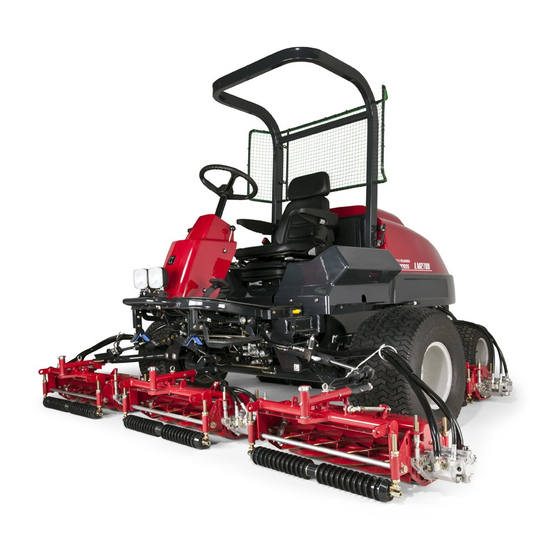
5-unit fairway mower
Hide thumbs
Also See for LM2700:
- Owner's operating manual (60 pages) ,
- Operator's manual (44 pages) ,
- Technical information (6 pages)
Table of Contents
Advertisement
Quick Links
Advertisement
Chapters
Table of Contents

Related Manuals for Baroness LM2700


Summary of Contents for Baroness LM2700
- Page 1 5-Unit Fairway Mower Service manual Serial No.10101- Ver.1.0...
- Page 2 The information described in this manual is subject to change for improvement without prior notice. When replacing parts, be sure to use genuine Baroness parts or parts designated by Kyoeisha. Note that the Baroness product warranty may not apply to defects caused by the use of parts from other companies.
-
Page 3: Table Of Contents
LM2700 Contents Safety............... Page 1-1 General inspection and repair.......Page 6-39 Main body............Page 7-1 Safe Operating Practices........Page 1-2 Safety Signs and Instruction Signs....Page 1-5 Maintenance........... Page 7-2 Disposal............Page 2-1 Specifications..........Page 7-2 Special Tool............ Page 7-4 Waste Disposal..........Page 2-2 Adjustment............Page 7-10... - Page 4 LM2700 Contents...
-
Page 5: Safety
LM2700 Safety Safe Operating Practices....... Page 1-2 Training...........Page 1-2 Preparation..........Page 1-2 Operation..........Page 1-3 Maintenance and storage....... Page 1-4 Safety Signs and Instruction Signs..Page 1-5 About Safety Signs and Instruction Signs............Page 1-5 Page 1-1... -
Page 6: Safe Operating Practices
LM2700 Safety Failure to adequately follow these safety Being driven too fast precautions may cause an accident resulting in Inadequate braking injury or death. The type of machine is unsuitable for its task Danger Danger Lack of awareness of the effect of... -
Page 7: Operation
LM2700 Safety Add fuel before starting the engine. Never Stay alert for humps and hollows and remove the cap of the fuel tank or add fuel other hidden hazards. while the engine is running or when the Never operate across the face of the engine is hot. -
Page 8: Maintenance And Storage
LM2700 Safety Look behind and down before backing up to Maintenance and storage be sure of a clear path. Disengage drives on level ground, lower the Do not carry passengers. attachments, set parking brake, stop engine Never operate while people, especially and remove key from ignition. -
Page 9: Safety Signs And Instruction Signs
Part numbers for decals that need to be first and negative last. replaced are listed in the parts catalog. Make sure that parts such as wires are not Order them from a Baroness dealer or touching each other and that their covers Kyoeisha. have not come off. - Page 10 LM2700 Safety Page 1-6 Safety Signs and Instruction Signs...
-
Page 11: Disposal
LM2700 Disposal Waste Disposal........Page 2-2 About the Waste disposal....... Page 2-2 Page 2-1... -
Page 12: Waste Disposal
LM2700 Disposal Waste Disposal About the Waste disposal Make sure that waste generated when servicing or repairing the machine is disposed of in accordance with local regulations. (e.g. waste oil, antifreeze batteries, rubber products, and wires etc.) Page 2-2 Waste Disposal... -
Page 13: Maintenance Standards And Maintenance
LM2700 Maintenance standards and maintenance Unit conversion........Page 3-2 Inch–millimeter conversion table.... Page 3-2 US unit–SI unit conversion table.....Page 3-3 Maintenance standards......Page 3-4 List of Maintenance Specifications..Page 3-4 Tightening torques......... Page 3-5 Standard tightening torques....Page 3-5 Principal tightening torques ....Page 3-8 Jacking up the machine....... -
Page 14: Unit Conversion
LM2700 Maintenance standards and maintenance Unit conversion Inch–millimeter conversion table 1 mm = 0.03937 in 1 in = 25.4 mm Fractions Decimals Fractions Decimals 1/64 0.015625 0.397 33/64 0.515625 13.097 1/32 0.03125 0.794 17/32 0.53125 13.494 3/64 0.046875 1.191 35/64 0.546875... -
Page 15: Us Unit-Si Unit Conversion Table
LM2700 Maintenance standards and maintenance US unit–SI unit conversion table To Convert Into Multiply By Miles Kilometers 1.609 Yards Meters 0.9144 Feet Meters 0.3048 Linear Measurement Feet Centimeters 30.48 Inches Meters 0.0254 Inches Centimeters 2.54 Inches Millimeters 25.4 mile Square Miles Square Kilometers 2.59... -
Page 16: Maintenance Standards
LM2700 Maintenance standards and maintenance Maintenance standards List of Maintenance Specifications LM2700 Engine model Kubota V2203-M-E3B No load rpm 975 - 2,800 rpm API Service grade class CF or 9.7 dm (9.7 L) (2.56 U.S. gal.) Quantity of engine oil... -
Page 17: Tightening Torques
LM2700 Maintenance standards and maintenance Tightening torques Standard tightening torques Bolts and Nuts Important A number of bolts are used in each part of this machine. Be sure to re-tighten the bolts and nuts, because they may be loosened at the earlier stage of the use. - Page 18 LM2700 Maintenance standards and maintenance General bolt Strength classification 4.8 Nominal diameter tib3yb-001 kgf-cm lb-in 3 - 5 30.59 - 50.99 26.55 - 44.26 7 - 9 71.38 - 91.77 61.96 - 79.66 14 - 19 142.76 - 193.74 123.91 - 168.17 29 - 38 295.71 - 387.49...
- Page 19 LM2700 Maintenance standards and maintenance Hydraulic hose The tightening torques for union joints and union adaptors with parallel pipe threads (G, PF) are shown in the table below. A union joint or adaptor will not become loose or leak as long as it is tightened by the specified torque.
-
Page 20: Principal Tightening Torques
LM2700 Maintenance standards and maintenance Principal tightening torques Tightening Torque by Model LM2700 Tighten the following bolts and nuts at the torque specified in the table. For thread locking adhesive, apply a middle strength thread locker (ThreeBond 1322 anaerobic adhesives). - Page 21 LM2700 Maintenance standards and maintenance Tightening torque Thread Location Code Part name locking kgf-cm lb-in adhesive 530.24 - 460.25 - Kingpin stopper K0013120552 Bolt, heat-treated M12-55 52 - 67 683.20 593.02 K1610000020 Tie rod end slotted nut 458.87 398.30 Tie rod...
-
Page 22: Jacking Up The Machine
LM2700 Maintenance standards and maintenance Jack-up Points Jacking up the machine About the Jacking up the machine Warning When replacing a tire or beginning any other maintenance or repairs, be sure to chock the wheels to prevent the machine from moving. - Page 23 LM2700 Maintenance standards and maintenance Front left frame rwyt62-044 Jack-up Points_003 Center of pivot Caution The jack-up point of the center of the pivot is not the center of the machine. Securely place the jack onto the jack-up point, and perform the operations with care.
-
Page 24: Greasing
LM2700 Maintenance standards and maintenance Greasing No. of Location greasing About Greasing points Pedal shaft fulcrum Since there may be adhesion or damage due to Foot brake lack of grease on moving parts, they must be greased. Lift arm fulcrum Add urea-based No. - Page 25 LM2700 Maintenance standards and maintenance Lift arm fulcrum Mower arm fulcrum shaft Mower units #1, #4 and #5 Mower units #1, #4 and #5 There is one greasing point on the lift arm There is one greasing point on each fulcrums which connect to each mower mower arm fulcrum shaft.
-
Page 26: Greasing Points
LM2700 Maintenance standards and maintenance Mower arm fulcrum Front roller There is one greasing point on each mower There is one greasing point each on the left unit. and right of each mower unit. 8bq62b-114 8bq62b-117 Greasing Points_008 Greasing Points_011... - Page 27 LM2700 Maintenance standards and maintenance Idle lever Rear left wheel There are two locations. 8bq62b-123 8bq62b-120 Greasing Points_016 Rear right wheel Greasing Points_013 Up/down lever 8bq62b-124 8bq62b-121 Greasing Points_017 Greasing Points_014 Pivot Middle between the rear wheels 8bq62b-122 Greasing Points_015...
- Page 28 LM2700 Maintenance standards and maintenance Page 3-16 Greasing...
- Page 29 LM2700 Engine Maintenance..........Page 4-2 Maintenance........... Page 4-2 Specifications......... Page 4-3 Specifications..........Page 4-3 Special Tool..........Page 4-4 Special tools list........Page 4-4 General inspection and repair....Page 4-4 Cooling system........Page 4-4 Air cleaner..........Page 4-5 Fuel Tank..........Page 4-5 Muffler.............Page 4-5 Inspection and repair of each section.............
-
Page 30: Maintenance
LM2700 Engine Maintenance Maintenance This machine is equipped with the Kubota vertical 4-cycle diesel engine V-2203-M-E3B. For details, please refer to the separate Engine Handling Manual and the Service Manual. Page 4-2 Maintenance... -
Page 31: Specifications
LM2700 Engine Specifications Specifications Model V2203-M-E3B Type Vertical 4-cycle liquid cooled Diesel Number of Cylinders Bore Stroke 87.0 mm x 92.4 mm (3.43" x 3.64") Total Displacement 2,197 cc (134.07 cu.in.) Weight (Dry) 170.0 kg (374.79 lbs) SAE Gross Intermittent 33.5 kW / 2,600 rpm (45.3 PS / 2,600 rpm) -
Page 32: Special Tool
LM2700 Engine Move the machine to a level surface. Special Tool Apply the parking brake, stop the engine, then remove the ignition key. Special tools list Warning No use of special tools is required. Never touch the engine or exhaust system. -
Page 33: Air Cleaner
LM2700 Engine Air cleaner Checking of the fuel line and connection A contaminated air cleaner element may cause Check the fuel line and its connection regularly. malfunction of the engine. Check for deterioration, damage, leakage or To maximize the life of the engine, clean the air poor connections, and replace the hose, cleaner properly. -
Page 34: Inspection And Repair Of Each Section
LM2700 Engine Inspection and repair of each section Cleaning of Dust-proof Mesh Cooling system Caution Precautions for Cleaning System Be sure to inspect or clean the dust-proof mesh according to the following procedure Clean the engine, oil cooler, radiator and before starting the machine. -
Page 35: Radiator
LM2700 Engine Lift up the dust-proof mesh to remove it, If the radiator has been contaminated with and carefully clean the front and back of the dust, be sure to clean it. dust-proof mesh with water or compressed Especially after operating the machine in a air. -
Page 36: Coolant
LM2700 Engine Coolant Caution Supply coolant after the engine has well Inspection of Coolant cooled down. For details on handling the engine, please refer to the separate Engine Operating Manual. Caution Warning The radiator cap is pressurized. Do not touch the radiator or coolant during... -
Page 37: Oil Cooler
LM2700 Engine If the coolant level in the reserve tank is Change of Coolant lower than the "LOW" mark, open the reserve tank cap and fill the tank with clean For details on handling the engine, please refer water up to the "FULL" mark. -
Page 38: Fan, Fan Belt
LM2700 Engine Fan, Fan Belt Cleaning of Oil Cooler Inspection of Fan and Fan Belt Caution An unclean oil cooler may cause overheating Caution or damage to the engine. The engine must be stopped when the belt is It may also cause malfunction of the hydraulic inspected. -
Page 39: Air Cleaner
LM2700 Engine If there is too much slack, loosen bolts A and B (that fix the alternator), and then Protection cover move the alternator to adjust the tension. Pulley housing After making adjustments, firmly tighten Gear motor bolts A and B. - Page 40 LM2700 Engine Press the reset button for the vacuum Cleaning of Air Cleaner indicator. For details on handling the engine, please refer to the separate Engine Handling Manual. A contaminated air cleaner element may cause malfunction of the engine. To maximize the life of the engine, clean the air cleaner properly.
-
Page 41: Fuel Filter
LM2700 Engine Lightly apply fuel to the packing of the Fuel filter new cartridge, and then properly hand- tighten the cartridge, without using the Replacement of Fuel Filter filter wrench. Important When installed, be careful that it is not contaminated with dirt or dust. -
Page 42: Fuel Pipe
LM2700 Engine Fuel pipe Fuel hose Clamp Inspection of Fuel Hose To the engine Fuel tank Danger Danger Engine Oil A damaged fuel hose may result in fuel leakage or fire. Recommended Oil Inspect the fuel hose and the tightening state Do not use special additives. - Page 43 LM2700 Engine Position the machine so that the engine will Important be level, and then insert the oil level gauge all the way to check the oil level. Do not mix different types of engine oil. Important Be sure to use engine oil that is classified as...
- Page 44 LM2700 Engine Replace the drain plug in the engine. Change of Engine Oil For details on handling the engine, please refer to the separate Engine Handling Manual. Warning When you change the engine oil, be sure to drain it into a bowl and discard it in accordance with local laws and regulations.
-
Page 45: Engine Oil Filter
LM2700 Engine Apply engine oil lightly to the gasket of a Timing for Replacing Engine Oil ■ new oil filter, then screw in the oil filter by hand until the gasket touches the adapter. Periodically replace the engine oil. Use a wrench to further screw in the oil filter After 50 hrs of by a one-half or three-quarter rotation. -
Page 46: Removal And Installation Of Each Section
LM2700 Engine Remove the four nuts, spring washers, and Removal and installation of each washers. section Engine Removal of Engine Disconnect the negative battery terminal. Remove the hood. (See "Removal of Hood" (Page 7-35) .) Important Be careful that removed parts do not fall into o3sknc-041 the engine. - Page 47 LM2700 Engine Disconnect the wire from the stop solenoid. Disconnect the glow wire, the wire for tachometer sensor, and the wire for water temperature gauge sensor. o3sknc-043 Removal of Engine_004 o3sknc-045 Stop solenoid Removal of Engine_006 Wire Glow wire Disconnect the battery ground wire and the Wire for tachometer sensor ground wire.
- Page 48 LM2700 Engine Disconnect the oil pressure switch wire and Loosen the hose band, and then remove the starter wire. the abrasion-resistant hose from the air cleaner. o3sknc-047 o3sknc-049 Removal of Engine_008 Removal of Engine_010 Oil pressure switch wire Hose band...
- Page 49 LM2700 Engine Caution Caution The fuel pump is connected to the fuel tank The relay box is connected to the electric with the fuel hose, so place it unobtrusively in parts with each wire, so place it unobtrusively a stable area.
- Page 50 LM2700 Engine Follow the steps below to remove the Remove the hydraulic hoses from the gear radiator hose. motor. Loosen the hose band, and then remove the upper and lower hoses. o3sknc-056 Removal of Engine_017 o3sknc-054 Gear motor Removal of Engine_015...
- Page 51 LM2700 Engine Remove the three bolts and the spring Important washers, and then remove the flywheel adapter from the engine flywheel. When removing the adjustment washers, check their installation positions and the quantity. Important Be sure to use hooks and hoist fittings that are adequately strong.
- Page 52 See the list in "Tightening torques" (Page 3-5) . Note that the Baroness product warranty may not apply to defects caused by incorrect or overtorque tightening etc. Important Be careful not to pinch wires or hoses.
-
Page 53: Radiator
LM2700 Engine Follow the steps below to remove the Radiator reserver tank, lower hose, and upper hose. Removal of Radiator Loosen the hose bands, and then remove the upper hose, lower hose, and drain hose from the radiator. Warning Remove the reserve tank. - Page 54 See the list in "Tightening torques" (Page 3-5) . Note that the Baroness product warranty may Caution not apply to defects caused by incorrect or Exercise care in the handling of the radiator overtorque tightening etc.
- Page 55 LM2700 Hydraulic system Maintenance..........Page 5-2 Hydraulic Oil......... Page 5-52 Air bleeding...........Page 5-53 Maintenance........... Page 5-2 Inspection and repair of each Specifications......... Page 5-3 section........... Page 5-54 Specifications..........Page 5-3 Hydraulic Oil......... Page 5-54 Hydraulic System Layout......Page 5-5 Hydraulic oil filter........Page 5-56 Flow of Hydraulic Oil.......Page 5-8...
-
Page 56: Maintenance
For those parts that must be repaired by the manufacturer, the overhaul procedure is not described in this manual. Request repairs for those parts from your dealer or Baroness. Please note that our product warranty may be void if you overhaul the device. -
Page 57: Specifications
LM2700 Hydraulic system Specifications Specifications EATON 72400 0 - 49.2 cm /rev Displacement (0 - 3.0 in /rev) 24.1 MPa High-pressure relief set Piston pump pressure (3,495.28 psi) 1.7 - 2.1 MPa Charge relief set pressure (246.54 - 304.55 psi)... - Page 58 LM2700 Hydraulic system 3.1 MPa Relief set pressure (449.60 psi) EATON V4205 150.0 L/min Flow (39.75 US gallons/min) Solenoid valve For cooling fan control 10.3 MPa Relief set pressure (1,498.65 psi) EATON V4209 21.0 L/min Flow (5.55 US gallons/min) EATON SV3 9.8 MPa...
-
Page 59: Hydraulic System Layout
LM2700 Hydraulic system Hydraulic System Layout dwb7jb-006 Hydraulic System Layout_002 Gear motor Gear pump Cartridge filter Electro-magnetic check valve Piston pump Suction filter Up/down cylinder Gear motor (MA7AD661) Filler neck breather Solenoid valve (V5259) 2WD/4WD changeover valve (V4205) 18 Orbitrol... - Page 60 LM2700 Hydraulic system Gear motor This is located in each unit to rotate the reel cutter. These convert the fluid energy from the pump to mechanical energy (rotation motion) by using two gears. Electro-magnetic check valve This keeps the hydraulic flow in one direction passing freely according to the cracking pressure of the electro-magnetic check valve and stops the flow in the reverse direction This stops the flow of the cylinders in sync with the proximity sensors.
- Page 61 LM2700 Hydraulic system Steering cylinder This is located between the rear wheels. According to the control valve that is activated depending on the steering operation, the flow of the fluid from the hydraulic pump is changed to steer the vehicle to the left or right.
-
Page 62: Flow Of Hydraulic Oil
LM2700 Hydraulic system Flow of Hydraulic Oil Flow of Oil during Forward Traveling zy6f9z-003 Flow of Oil during Forward Traveling_001 shows flow of oil. The flow of oil shows that for 4WD forward traveling. shows port name inside. Piston pump... - Page 63 LM2700 Hydraulic system Flow of Oil during Raising Mower Unit, with Power Steering Turning to Left qwbqfy-003 Flow of Oil during Raising Mower Unit, with Power Steering Turning to Left_001 shows flow of oil. The flow of oil shows that for raising the mower unit, turning the power steering to left.
- Page 64 LM2700 Hydraulic system Flow of Oil during Cutting with Mower Unit a4d9ch-003 Flow of Oil during Cutting with Mower Unit_001 shows flow of oil. The flow of oil shows that for cutting with the mower unit. shows port name inside.
-
Page 65: General Instructions
LM2700 Hydraulic system General instructions Hydraulic fitting Bite type tube fitting Hydraulic hose Preliminary tightening (Preset) Hydraulic hoses are subjected to excessive load when weathered, exposed to the sun or Cut the tube at the designated length at a chemicals, stored in a very hot storage right angle. - Page 66 LM2700 Hydraulic system Insert the nut and sleeve into the tube. Put the tube end onto the hole bottom of Note the direction of the sleeve. the temporary tightening jig and tighten the nut slowly to the point where the tube can no longer be rotated by hand.
- Page 67 LM2700 Hydraulic system Fasten the nut and check that the sleeve end is a few mm apart from the tube end and the sleeve will not move in axial direction (it is allowed to move in the circumferential direction). w7s31b-010...
- Page 68 LM2700 Hydraulic system Make sure that the thread portion, sheet Adjustable Elbow ■ surface of the O-ring port, and O-ring are not contaminated with foreign objects. Apply oil or grease to the sheet surface and O-ring before installation. jf65lf-001 Adjustable Elbow_001 Make sure that the positions of the nut, washer, and O-ring are correct.
- Page 69 LM2700 Hydraulic system Caution Important Be careful to never give the locknut more If a used taper pipe (PT) thread joint retains than one turns. If you give it more than one the residue of old sealing tape, using it again...
-
Page 70: Towing
LM2700 Hydraulic system How to Use the Sealing Tape ■ Important Using the sealing tape with its end out of the edge face may cause a trouble of the machine due to its debris invading the hydraulic circuit. ugh2b1-002 How to Use the Sealing Tape_002... -
Page 71: Neutral
LM2700 Hydraulic system In the event of loss of mobility due to engine Drain all the hydraulic oil from hydraulic tank trouble or the like of, movement is possible and hydraulic equipment other than the through towing or hand driving. -
Page 72: Hydraulic Circuit Flow
LM2700 Hydraulic system Hydraulic circuit flow Traveling circuit Forward traveling (4WD) ms5j2m-004 Forward traveling (4WD)_001 Page 5-18 Hydraulic circuit flow... - Page 73 LM2700 Hydraulic system Backward yyuoor-004 Reverse_001 Hydraulic circuit flow Page 5-19...
-
Page 74: Raise/Lower Circuit
LM2700 Hydraulic system Raise/lower circuit Rising of up/down cylinder qhyyzc-007 Rising of up/down cylinder_001 Page 5-20 Hydraulic circuit flow... - Page 75 LM2700 Hydraulic system Up/down cylinder lowering (operation) jtjf9j-007 Up/down cylinder lowering (operation)_001 Hydraulic circuit flow Page 5-21...
-
Page 76: Steering Circuit
LM2700 Hydraulic system Steering circuit Steering cylinder counter-clockwise turning j55lma-004 Steering cylinder counter-clockwise turning_001 Page 5-22 Hydraulic circuit flow... - Page 77 LM2700 Hydraulic system Steering cylinder clockwise turning lb5pa8-004 Steering cylinder clockwise turning_001 Hydraulic circuit flow Page 5-23...
-
Page 78: Reel Rotation Circuit
LM2700 Hydraulic system Reel Rotation Circuit Reel positive rotation (operation) k46fs2-002 Reel positive rotation (operation)_001 Page 5-24 Hydraulic circuit flow... - Page 79 LM2700 Hydraulic system Reel Reverse Rotation (Back Lapping) 5kfhjl-002 Reel Reverse Rotation (Back Lapping)_001 Hydraulic circuit flow Page 5-25...
-
Page 80: Cooling Fan Circuit
LM2700 Hydraulic system Cooling fan circuit 7jkcv2-002 Cooling fan circuit_001 Page 5-26 Hydraulic circuit flow... -
Page 81: Special Tool
LM2700 Hydraulic system Special Tool List of Special Tools Pressure gauge for high pressure measurements Pressure: For the range of 0 - 35 MPa For the range of 0 - 5,076.40 psi K4701000010 For the range of 0 - 356.90 kgf/cm Primarily used for measuring the pressure of high-pressure parts. - Page 82 LM2700 Hydraulic system Pressure gauge seal Inserted between the pressure gauge K4701000050 and the pressure gauge joint. vasdfi-005 Gauge valve Used to temporarily shut off the fluid to be measured during maintenance, K4701000060 inspection, or repair etc. of the pressure gauge.
- Page 83 LM2700 Hydraulic system Female connector 1015-04 Used as a connector to attach the K3009000290-Y hydraulic hose to the pressure gauge. vasdfi-007 Cast iron T-joint PT3/8 PF3/8 Used to insert the pressure gauge K3024000042-Y between the hydraulic hoses. vasdfi-013 Special adapter PF1/4 PT3/8...
- Page 84 LM2700 Hydraulic system Adapter 1013-9 Two of these are used as an elbow for K3000090002-Y the T-joint during pressure measurements. q9c6v6-008 WP280-6 hose 1-600 Used as a hydraulic hose for high K3107210600 pressure to extremely low pressure measurements. vasdfi-008 WP210-9 hose 1-490...
- Page 85 LM2700 Hydraulic system Screw cap (male) PF1/2 Used as a plug when the hydraulic K3008000542-Y hose is removed. q9c6v6-001 Screw cap (female) PF1/2 Used as a plug when the hydraulic K3008000502-Y hose is removed. q9c6v6-002 Special bushing 3/4-16UNFPT1/4 Used as a bushing when installing the...
- Page 86 LM2700 Hydraulic system 45 elbow 1035-6 Used as an elbow for the special K3003060002-Y bushing during pressure measurements. q9c6v6-004 O-ring connector 1096-6 Used as a connector when installing K3008000342-Y the pressure gauge to the hydraulic measurement port. q9c6v6-005 O-ring connector PF1/4PF1/4...
-
Page 87: Measurement
LM2700 Hydraulic system Always clean the machine before hydraulic Measurement measurement. Remember that the machine must always be kept clean for hydraulic Note measurement. Contamination may lead to The most effective way of solving problems in clogging or breakage of the hydraulic circuit. -
Page 88: Traveling Circuit
LM2700 Hydraulic system Traveling Circuit Forward g5t8is-010 Forward_001 Page 5-34 Measurement... - Page 89 LM2700 Hydraulic system Attach the high pressure gauge on the Caution forward side measuring port connector. Before starting pressure measurement, make sure that there is no people around the machine. The forward side measuring port connector is located behind the 2WD/4WD changeover valve.
- Page 90 LM2700 Hydraulic system Backward 7edlvx-010 Reverse_001 Page 5-36 Measurement...
- Page 91 LM2700 Hydraulic system Attach the pressure gauge to the reverse Caution side measuring port connector. Before starting pressure measurement, make sure that there is no people around the machine. The reverse side measuring port connector is located behind the 2WD/4WD changeover valve.
-
Page 92: Up/Down Circuit
LM2700 Hydraulic system Up/Down circuit z4kw7w-020 Up/Down circuit_001 Page 5-38 Measurement... - Page 93 LM2700 Hydraulic system Hydraulic hose A Caution Adapter Before starting pressure measurement, make Hydraulic hose B sure that there is no people around the Pressure gauge for high pressure machine. measurements Lower the mower units. Make sure that the parking brake is applied.
-
Page 94: Steering Circuit
LM2700 Hydraulic system Steering Circuit 9idjnn-015 Steering Circuit_001 Page 5-40 Measurement... - Page 95 LM2700 Hydraulic system The normal pressure is 6.9 MPa (1,000.73 Caution psi) when the handle is turned rightward Before starting pressure measurement, make completely. sure that there is no people around the machine. Remove the hydraulic hose from the elbow attached to the hydraulic cylinder.
-
Page 96: Charge Circuit
LM2700 Hydraulic system Charge Circuit zg85f8-015 Charge Circuit_001 Page 5-42 Measurement... - Page 97 LM2700 Hydraulic system Start the engine, and rev it up to the Caution maximum rpm. Before starting pressure measurement, make The normal pressure is 1.7 to 2.1 MPa sure that there is no people around the (246.56 - 304.57 psi).
-
Page 98: Reel Rotation Circuit
LM2700 Hydraulic system Reel Rotation Circuit Mower Units #2/#3 gy2el3-012 Mower Units #2/#3_001 Page 5-44 Measurement... - Page 99 LM2700 Hydraulic system Install the hydraulic hose of the pressure gauge for measuring high pressures onto the measuring port of the mower rotation valve #2/#3. gy2el3-007 Mower Units #2/#3_002 Mower rotation valves #1/#4/#5 Mower rotation valves #2/#3 gy2el3-009 Mower Units #2/#3_004...
- Page 100 LM2700 Hydraulic system Caution The wood board must be a stout one. Make sure that the wood board surely gets on top of the front stay. Insert a stout wood board into the reel cutter of mower unit #3 to stop the rotation of the reel cuter.
- Page 101 LM2700 Hydraulic system Mower Units #1/#4/#5 syaq7s-008 Mower Units #1/#4/#5_001 Measurement Page 5-47...
- Page 102 LM2700 Hydraulic system Install the hydraulic hose of the pressure gauge for measuring high pressures onto the measuring port of the mower rotation valve #1/#4/#5. gy2el3-007 Mower Units #1/#4/#5_002 Mower rotation valves #1/#4/#5 Mower rotation valves #2/#3 syaq7s-007 Mower Units #1/#4/#5_004...
- Page 103 LM2700 Hydraulic system Insert a stout wood board into the reel cutter of mower unit #4 to stop the rotation of the reel cuter. Caution The wood board must be a stout one. Make sure that the wood board surely gets on top of the front stay.
-
Page 104: Cooling Fan Circuit
LM2700 Hydraulic system Cooling Fan Circuit hlnjwg-013 Cooling Fan Circuit_001 Page 5-50 Measurement... -
Page 105: General Inspection And Repair
LM2700 Hydraulic system Install the screw caps to the hydraulic hose Caution and hydraulic motor connected to the Before starting pressure measurement, make solenoid. sure that there is no people around the machine. Stop the engine, and set the parking brake. -
Page 106: Hydraulic Hose, Piping
If necessary, repair before See the list in "Tightening torques" (Page operating the machine. 3-5) . Note that the Baroness product warranty may Hydraulic Oil not apply to defects caused by incorrect or overtorque tightening etc. Important... -
Page 107: Air Bleeding
LM2700 Hydraulic system Stop the engine, and then remove the key. If no abnormality is found, operate normally and maintain according to the maintenance Warning schedule. Be sure to depressurize the hydraulic system Air bleeding before inspecting or repairing it. -
Page 108: Inspection And Repair Of Each Section
LM2700 Hydraulic system Make sure that the traveling pedal and all the Then, gradually increase operation load drives of the operating machine are in while running for 10 minutes. neutral position. Stop the machine, check the amount of Start the engine and depress the traveling hydraulic oil and add it as necessary. - Page 109 LM2700 Hydraulic system Hydraulic Oil Supply Change of Hydraulic Oil Important Warning Do not mix different types of oil. When you change the hydraulic oil, be sure to drain it into a bowl and discard it in accordance with local laws and regulations.
-
Page 110: Hydraulic Oil Filter
LM2700 Hydraulic system Open the tank cap, and then pour new oil Timing for Raplacing Hydraulic Oil ■ from the fill port until the oil level reaches the middle of the oil gauge on the hydraulic Important tank. The hydraulic tank capacity is Contamination of hydraulic oil may cause approximately 44.0 dm... - Page 111 LM2700 Hydraulic system Wipe out all of the old liquid gasket from Replacing Timing of Hydraulic Oil Filter ■ the hydraulic tank, the intake hose joint fitting and the intake port packing. Important Contamination of hydraulic oil filter may cause malfunction of the hydraulic system.
-
Page 112: Removal And Installation Of Each Section
See the list in "Tightening torques" (Page 3-5) . Remove the two bolts, spring washers, and Note that the Baroness product warranty may washers used to install the gear motor, pull not apply to defects caused by incorrect or out the gear motor in the direction of the overtorque tightening etc. -
Page 113: Raise/Lower Cylinder
See the list in "Tightening torques" (Page Remove the two cotter pins, slotted nuts 3-5) . and spring washers. Note that the Baroness product warranty may Remove the up/down cylinder. not apply to defects caused by incorrect or overtorque tightening etc. - Page 114 LM2700 Hydraulic system Remove elbow A and elbow B (for orifice) Mower Units #4/#5 ■ from the up/down cylinder. Important Caution There are two types of elbows. Exercise care in handling the hydraulic Be careful when removing the elbow on the cylinder since it is heavy.
- Page 115 After the installation, check if there is no oil leakage in each part. Caution See "Tightening torques" (Page 3-5) . Note that the Baroness product warranty may not apply to defects caused by incorrect or overtorque tightening etc. kct3xp-005 Important...
-
Page 116: Wheel Motor
LM2700 Hydraulic system Remove the two adapters. Wheel motor Removal of Front Wheel Motor Important Take note of the installation position when removing the hydraulic hose. Important Make sure that no dirt or dust enters the ports ea77qp-003 of the hydraulic system. - Page 117 LM2700 Hydraulic system Remove the four bolts, spring washers, and Frame nuts used to install the motor, and then Wheel motor remove the motor mounting disk. Return adapter Caution Two people should work together on the wheel motor since it is heavy.
- Page 118 Remove the three hydraulic hoses from the wheel motor. See the list in "Tightening torques" (Page 3-5) . Install the screw caps to the hydraulic Note that the Baroness product warranty may hoses. not apply to defects caused by incorrect or overtorque tightening etc. Important...
-
Page 119: Control Valve
After the installation, check if there is no oil leakage in each part. Caution See "Tightening torques" (Page 3-5) . d3mo2k-003 Note that the Baroness product warranty may Removal of Control Valve_001 not apply to defects caused by incorrect or Control Valve overtorque tightening etc. -
Page 120: Gear Pump
Remove the three nuts, spring washers and Caution bolts, and then remove the control valve. See "Tightening torques" (Page 3-5) . Note that the Baroness product warranty may not apply to defects caused by incorrect or overtorque tightening etc. Important... - Page 121 LM2700 Hydraulic system Drain the hydraulic oil. (See "Change of Install a cap to the hydraulic hoses and the Hydraulic Oil" (Page 5-55) .) hydraulic fittings of the removed gear pump. Important Before removing the hydraulic hoses and pipes, check their installation positions.
- Page 122 LM2700 Hydraulic system Remove the two nuts, spring washers, Caution washers and the bolts, and then remove The left and right UNC bolts used for the right pump support plate. installation are the same. Do not confuse the UNC bolts with other bolts.
- Page 123 LM2700 Hydraulic system Pull out the gear pump slowly in the Caution direction of the arrow, and remove the UNC bolts and then the gear pump. Check the installation of the caps, screw caps, etc. again before removing the elbow, flanges, etc.
-
Page 124: Piston Pump
3gzzho-012 Caution Removal of Piston Pump_001 See "Tightening torques" (Page 3-5) . Note that the Baroness product warranty may not apply to defects caused by incorrect or overtorque tightening etc. Page 5-70 Removal and installation of each section... - Page 125 LM2700 Hydraulic system Screw rod Important Bolt Before removing the hydraulic hoses and Trunnion lever pipes, check their installation positions. Spring washer A Loosen the hose band of the adjustable Spring washer B elbow, and remove the suction hose from the piston pump.
- Page 126 LM2700 Hydraulic system Cut the banding band on the side of the Caution piston pump. Loosen the hose band, and then remove When loosening the nuts of pipes, be sure to the suction hose from the adjustable elbow. fix the Tee and elbow before loosening the nuts.
- Page 127 LM2700 Hydraulic system Loosen the bolt of the drive disc and Frame remove the drive disc of the pump side Piston pump installed onto the piston pump in the Bolt direction of the arrow. Spring washer Washer Remove adjustable elbow A.
-
Page 128: Reel Rotation Valve #2/#3
After the installation, check if there is no oil leakage in each part. Caution See "Tightening torques" (Page 3-5) . Note that the Baroness product warranty may not apply to defects caused by incorrect or overtorque tightening etc. Important Make sure of the installing locations of the hydraulic hoses and pipes and do not install them at the wrong locations. - Page 129 After the installation, check if there is no oil leakage in each part. Caution See "Tightening torques" (Page 3-5) . Note that the Baroness product warranty may not apply to defects caused by incorrect or overtorque tightening etc. bgdx9a-003 Removal of Reel Rotation Valve #2/#3_003...
- Page 130 LM2700 Hydraulic system Remove the hydraulic pipes A, B, and C, Reel Rotation Valve #1/#4/#5 and hose from the reel rotation valve #1/#4/#5. Removal of Reel Rotation Valve #1/#4/#5 Start the engine of this machine, and then lower all mower units.
-
Page 131: Reel Rotation Valve #1/#4/#5
After the installation, check if there is no oil leakage in each part. Caution See "Tightening torques" (Page 3-5) . Note that the Baroness product warranty may not apply to defects caused by incorrect or w7zkd4-003 overtorque tightening etc. Removal of Reel Rotation Valve #1/#4/#5_003... -
Page 132: 2Wd/4Wd Changeover Valve
LM2700 Hydraulic system Remove the hydraulic pipes from the 2WD/4WD Changeover Valve 2WD/4WD changeover valve. Removal of 2WD/4WD Changeover Valve Open the rear cover. Important Before removing the wires, check their installation positions. Disconnect the connector of the 2WD/4WD changeover valve solenoid. -
Page 133: Oil Cooler
Caution Removal of Oil Cooler_002 See "Tightening torques" (Page 3-5) . Dust-proof mesh Note that the Baroness product warranty may Handle not apply to defects caused by incorrect or overtorque tightening etc. Important Make sure of the installing locations of the hydraulic pipes and do not install them at the wrong locations. - Page 134 LM2700 Hydraulic system Oil cooler Caution Hydraulic hose Exercise care in the handling of the oil cooler Elbow since its core is easily scratched. Radiator Remove the rubber hook, hold the upper oil Install the screw caps to the hydraulic cooler fitting, and tilt it forward slowly.
- Page 135 After the installation, check if there is no oil leakage in each part. Caution See "Tightening torques" (Page 3-5) . Note that the Baroness product warranty may not apply to defects caused by incorrect or overtorque tightening etc. pt9ba8-012 Removal of Oil Cooler_006...
-
Page 136: Steering Cylinder
Remove the steering cylinder. Caution See "Tightening torques" (Page 3-5) . Note that the Baroness product warranty may not apply to defects caused by incorrect or overtorque tightening etc. Important Make sure of the installing locations of the... -
Page 137: Manifold Valve (For Traveling)
LM2700 Hydraulic system Manifold Valve (for Traveling) Important Before removing the hydraulic hoses and Removal of Manifold Valve (Forward) pipes, check their installation positions. Remove mower unit #1. (See "Removal of Mower Unit" (Page 8-10) .) Remove the hydraulic hoses and pipes Jack up the both front wheels and support from the manifold valve. - Page 138 After the installation, check if there is no oil leakage in each part. Caution See the list in "Tightening torques" (Page 3-5) . Note that the Baroness product warranty may not apply to defects caused by incorrect or w6hn8f-002 overtorque tightening etc. Removal of Manifold Valve (Forward)_003...
- Page 139 LM2700 Hydraulic system Remove the elbow, adapter, O-ring Important connector A, and O-ring connector B from Before removing the hydraulic hoses and the manifold valve. pipes, check their installation positions. Remove the four hydraulic hoses and three hydraulic pipes from the manifold valve.
-
Page 140: Manifold Valve (For Cylinder)
Caution See the list in "Tightening torques" (Page 3-5) . Note that the Baroness product warranty may not apply to defects caused by incorrect or overtorque tightening etc. Important Make sure of the installation positions of the... - Page 141 See the list in "Tightening torques" (Page 3-5) . Note that the Baroness product warranty may not apply to defects caused by incorrect or overtorque tightening etc. Important Make sure of the installing locations of the hydraulic hoses and pipes and do not install them at the wrong locations.
-
Page 142: Cooling Fan Rotation Valve
Hydraulic pipe See the list in "Tightening torques" (Page Frame 3-5) . Bolt Note that the Baroness product warranty may not apply to defects caused by incorrect or Spring washer overtorque tightening etc. Important Make sure of the installing locations of the hydraulic hoses and do not install them at the wrong locations. -
Page 143: Gear Motor (For Cooling Fan)
LM2700 Hydraulic system Gear Motor (for Cooling Fan) Gear motor Bolt Removal of Gear Motor (for Cooling Fan) Spring washer Washer Important Before removing the hydraulic hose, check its Remove the gear motor from the cooling installation position. fan mounting bracket in the direction of the arrow. -
Page 144: Electro-Magnetic Check Valve (Anti-Falling)
After the installation, check if there is no oil leakage in each part. Caution See the list in "Tightening torques" (Page 3-5) . Note that the Baroness product warranty may not apply to defects caused by incorrect or overtorque tightening etc. 6271vs-001 Removal of Electro-Magnetic Check Valve_001... -
Page 145: Fuel Port Breather
Hydraulic tank See the list in "Tightening torques" (Page Filler neck breather 3-5) . Roundhead screw Note that the Baroness product warranty may not apply to defects caused by incorrect or Installation of Filler Neck Breather overtorque tightening etc. Caution... -
Page 146: Hydraulic Tank
Caution "Removal of Steering Column" (Page 7-31) .) See "Tightening torques" (Page 3-5) . Note that the Baroness product warranty may Important not apply to defects caused by incorrect or Before removing the hydraulic hose, check its overtorque tightening etc. - Page 147 LM2700 Hydraulic system Hydraulic tank Important Frame Before removing the wires, check their Side cover mounting bracket installation positions. Bolt Loosen the hose bands, and then remove Spring washer the suction hose. Remove the level switch. (See "Removal of Disconnect the level switch wire.
- Page 148 After the installation, check if there is no oil leakage in each part. Caution See "Tightening torques" (Page 3-5) . Note that the Baroness product warranty may not apply to defects caused by incorrect or overtorque tightening etc. Important Make sure of the installing locations of the hydraulic hoses and pipes and do not install them at the wrong locations.
-
Page 149: Electrical System
LM2700 Electrical system Maintenance..........Page 6-2 Tank Unit..........Page 6-34 Rotation Sensor (Electromagnetic About Maintenance.........Page 6-2 Pickup)..........Page 6-34 Specifications......... Page 6-2 Buzzers..........Page 6-35 Level Switch..........Page 6-36 Adjusted Value........Page 6-2 Delay Timer.......... Page 6-37 Electrical Part Layout......Page 6-3 CA1 Relay..........Page 6-38 Special Tool..........Page 6-8... -
Page 150: Maintenance
LM2700 electrical system. For daily inspections and maintenance as well as machine handling, refer to the LM2700 Operator's Manual and Parts Catalog. Also, for details for handling of the battery, please refer to the separate Battery Instruction Manual. -
Page 151: Electrical Part Layout
LM2700 Electrical system Electrical Part Layout 25 24 17 18 19 20 erq4ky-005 Electrical Part Layout_002 Proximity sensor (position detection Seat switch Fuel Gauge switches) Electro-magnetic check valve Delay timer Rocker switch Tank unit Safety switches Pilot lamp Relay comp. (starter) - Page 152 LM2700 Electrical system Proximity sensor (position detection switches) A proximity sensor is one of the safety switches that constitute the interlock system. Proximity sensors (position detection switches) are attached to the base parts of mower arms #1 and #3. They detect the rise of the mower arms and stop the reel cutter rotation.
- Page 153 LM2700 Electrical system Seat switch [NO type (push to turn on)] The seat switch is one of the safety switches that constitute the interlock system. It is located at the center of the seat cushion. Delay timer The delay timer is located at the right inside of the side cover, and if you leave the seat for 0.9 or more seconds while driving this machine, the delay timer stops supplying power to the engine stop solenoid.
- Page 154 LM2700 Electrical system Fuel Gauge The fuel gauge indicates the quantity of fuel inside the fuel tank. It is located on the right control panel. Rocker switch The rocker switches are used as the reel rotation switch, reel reverse switch, 2WD/4WD changeover switch, traveling/working switch, and traveling/working reverse switch.
- Page 155 LM2700 Electrical system Fusible Link The fusible link functions as the main fuse for the entire electrical circuit, and as the fuse for the charge circuit. It is equipped with a specialized fuse (50A) cartridge. The fuse block is located at the right front under the hood.
-
Page 156: Special Tool
LM2700 Electrical system Special Tool Specific weight and remaining capacity of battery Discharged Specific weight Remaining Special tools list electrical quantity (20 ° C) capacity (%) No use of special tools is required. 1.16 Measurement 1.12 Battery Measurement of specific weight of 12V battery Check all the cells after charge. -
Page 157: Interlock System
LM2700 Electrical system After charging is completed, fill the battery To operate (reel rotation), cells with distilled water (if the battery is in An operator sits on the seat. use). Set the position of the traveling/working After charging is completed, measure and changeover switch to "Working."... - Page 158 LM2700 Electrical system Interlock System Operation Requirements Traveling/ Reel reverse Reel rotation Traveling Working Seat Parking brake switch switch pedal changeover switch OFF (Take To start the engine, ON (Sitting) ON (Applied) - the foot off) ON (Forward "Traveling" To travel,...
-
Page 159: Adjustment
LM2700 Electrical system Adjustment Warning Be sure to stop the engine before adjusting Proximity Sensor the proximity sensor. Reel Rotation Circuit Stop the engine. Mower Units #1/#4/#5 ■ Important Note: This operation should be performed by two The rotations/stops of the operating reel persons. - Page 160 LM2700 Electrical system Frame Warning Lift arm #1 Be sure to stop the engine before adjusting the proximity sensor. Proximity sensor Stop the engine. Switch mounting bracket Bolt Important ■ Mower Units #2/#3 This operation should be performed by two persons.
- Page 161 LM2700 Electrical system Follow the steps below to adjust the Traveling/Working Circuit proximity sensor. Start the engine. Loosen the bolts so that the switch mounting bracket can be moved in the Turn the traveling/working changeover direction of the arrow. switch to "Working," and raise the mower units.
- Page 162 LM2700 Electrical system Adjust the heights of mower units #4 and Push in the knob of the electro-magnetic #5 to 390.0 mm (15.35 in) by hand. valve of mower units #4 and #5. Turn the knob 180 degrees in an anticlockwise fashion to set it back to the original position.
-
Page 163: Parking Brake Switch
LM2700 Electrical system Follow the steps below to adjust the Parking Brake Switch proximity sensor. The parking brake is equipped with a parking Loosen the two bolts so that the switch brake switch, one part of the interlock system. mounting bracket can be moved. -
Page 164: Electrical Components
LM2700 Electrical system Electrical components Notch Parking brake stopper About the Electrical components With the parking brake at notch 5, adjust adjusting nut A and adjusting nut B of the Warning parking brake switch to create a slight When servicing electrical components, be clearance at the switch contact point. - Page 165 LM2700 Electrical system Reel Rotation Circuit 2WD/4WD Changeover Circuit The rotation of the reel cutter is controlled by 2WD/4WD changeover is controlled by the the opening/closing of the reel rotation switch, 2WD/4WD changeover switch (rocker switch), terminal relay, proximity sensor, and mower terminal relay, and the opening/closing of unit rotation solenoid.
- Page 166 LM2700 Electrical system Traveling/Working Circuit Anti-Falling Circuit Set the traveling/working changeover switch to The electro-magnetic check valve is used to the "Working" position, and then shift the keep all mower units raised. mower unit up/down lever to the "UP" position...
-
Page 167: Rocker Switch
LM2700 Electrical system Seat Switch Switch operation part Parking brake switch The seat switch is located right underneath the Wire seat and is not usually conducted. It is normal if it is conducted when seated Rocker Switch (pressed). The rocker switchs are located in the operation... -
Page 168: Proximity Sensor
LM2700 Electrical system Proximity sensor Inspection of Action Indicator Proximity sensors detect that objects are nearby Caution through non-contact methods . Do not short-circuit the battery terminals. Connect the battery (+) to the connector terminal (brown/+), and the battery (-) to the connector terminal (blue/-). -
Page 169: Terminal Relay
LM2700 Electrical system It is normal if the voltage between the Inspection of Control Output connector terminals 2 and 3 is 0 V when the object to be detected is close to the Caution proximity sensor, and the voltage between the connector terminals 2 and 3 is battery Do not short-circuit the battery terminals. - Page 170 LM2700 Electrical system Inspect the remaining three circuits in the Cover same way. Between 10 and 14 ・ Power relay Between 11 and 15 ・ Inspection of Terminal Relay Between 12 and 16 ・ Have ready a simple terminal relay.
-
Page 171: Solenoid Valve
LM2700 Electrical system Normal operation is when there is Solenoid Valve conduction between relay terminals 5 and 6 and no conduction between relay terminals Reel Rotation Valve 3 and 4. The reel rotation valves for the front three mower units and for the rear two mower units are located on the left side below the seat and on the right side below the seat, respectively. - Page 172 LM2700 Electrical system 2WD/4WD Changeover Valve Electro-Magnetic Check Valve The 2WD/4WD changeover valve is located The electro-magnetic check valves are located below the radiator, behind the seat. in cylinders #4 and #5. It controls 2WD/4WD operation. The hydraulic When the traveling/working changeover switch...
-
Page 173: Power Relay
LM2700 Electrical system Power Relay Fan Rotation Valve The fan rotation valve controls ON/OFF of the Reel Rotation Relay gear motor of the radiator fan. The reel rotation relay controls the rotation of the reel with the power relay [MR5A602A1K]... - Page 174 LM2700 Electrical system Normal operation is when there is Seat/Brake Relay continuity between relay terminals 3 and 6 and no continuity between relay terminals The seat/brake relay is the interlock system 4 and 5. associated with the seat switch and the brake...
-
Page 175: Work Lamp
LM2700 Electrical system It is normal if there is no conduction Work Lamp between both of relay terminal 3 and 5, 6 and 7. Note: Depending on the specifications, this function may not be available. The work lamps are located on the front part of the machine. -
Page 176: Key Switch
LM2700 Electrical system Note: Key Position and Device Operation Wiring diagram ON (Run) ■ The diesel engine on the machine runs or stops based on the fuel supply. When the key is set to the "OFF" position, the engine stop solenoid is turned off, and fuel is shut off. -
Page 177: Pilot Lamps
LM2700 Electrical system Glow (thermo-start) START ■ ■ When the ignition key is kept in the "GLOW" The engine starts by rotating the starter the position, the glow plug is generating heat and magnet switch of which is energized with the the thermo-start lamp is turned on. -
Page 178: Fuel Gauge
LM2700 Electrical system Charge Engine Oil Pressure The lamp lights up when the ignition key is set The lamp turns on when the ignition key is set to the "ON" position before the engine starts. It to the "ON" position before the engine starts. It... -
Page 179: Water Temperature Gauge
LM2700 Electrical system Tachometer/Hour Meter The tachometer is located on the operation panel, connected to a rotation sensor in the engine flywheel area and displays the signal output from the rotation sensor as an rpm value. The hour meter displays the total operation time of the engine. -
Page 180: Starter Relay
LM2700 Electrical system When the ignition key is set and held to the Starter Relay "GLOW" position, the thermo-start lamp turns on for 5 seconds. Starter relay is located on the operation panel, The timer unit is activated with the "glow" and and it controls starting of the starter by receiving "starter start"... -
Page 181: Fuse Box
LM2700 Electrical system Fuse Box Replacement of Fuse Respective electrical equipments are connected Important from the key switch through fuses in the fuse box which is located in the hood. To remove the fuse, use the tools in the tool Fuse standards are "mini fuses for automobiles". -
Page 182: Tank Unit
LM2700 Electrical system Rotation Sensor (Electromagnetic Pickup) Solenoid Specifications The rotation sensor (electromagnetic pickup) is Rated DC 12 V located in the engine flywheel area and it Voltage detects the rpm by means of the flywheel ring Rated 1.5 A... -
Page 183: Buzzers
LM2700 Electrical system Buzzers Hydraulic Oil Level Buzzer Water Temperature Buzzer The hydraulic oil level buzzer is a buzzer that warns about insufficient oil and is connected to The water temperature buzzer is a warning the level switch on the hydraulic tank. -
Page 184: Level Switch
LM2700 Electrical system Level Switch Removal of Level Switch The level switch is located on the top of the Caution hydraulic tank and switches "ON" and "OFF" according to the rise and fall of the float. (The Adhesive is applied on the packing between arrow indicates the float travel distance.) -
Page 185: Delay Timer
Caution +12V See "Tightening torques" (Page 3-5) . SOL COIL Note that the Baroness product warranty may SEAT SW not apply to defects caused by incorrect or overtorque tightening etc. Apply adhesive to the new packing. -
Page 186: Ca1 Relay
LM2700 Electrical system Connect lamp line 2 to the battery (-). CA1 Relay Connect switch line 2 to the battery (-). CA1 relay is used for the circuit of the reel When the switch is turned "ON," the lamp reverse switch, rotation stop circuits of the turns on. -
Page 187: General Inspection And Repair
LM2700 Electrical system Normal operation is when there is General inspection and repair conduction between relay terminals 5 and 3 and no conduction between relay terminals Battery 5 and 4. Handling of the battery For details on handling the battery, please refer to the separate Battery Instruction Manual. - Page 188 LM2700 Electrical system Danger Danger Danger Danger Do not allow anyone to handle the battery Do not allow anyone to handle the battery who does not fully understand the correct who does not fully understand the correct battery handling procedures and relevant battery handling procedures and relevant dangers.
- Page 189 LM2700 Electrical system Inspection of the mounting bracket Caution Ensure that the battery is firmly secured by If the electrolyte overflows from the battery, the mounting bracket. wipe it with a wet cloth. If it is not, tighten the nuts securing the Failure to do so could cause damage to the battery until it is firmly secured.
- Page 190 LM2700 Electrical system Replacement of Battery Important When adding distilled water, be careful not to When replacing the battery, note the following add an excessive amount. precautions and be sure to turn off the power switch etc., stop the engine, and remove the Inspection of the electrolyte level and key before replacement.
- Page 191 LM2700 Electrical system Loose the mounting bracket and remove Caution the old battery. Select a battery that has the same terminal positions (the positions of the positive and negative terminals) as the old one. Installing a battery that has different terminal positions could cause damage to the cables.
- Page 192 LM2700 Electrical system Firmly secure the negative cable to the Warning negative terminal. Charging the battery mounted on the vehicle may cause ignition, explosion, or damage on the vehicle or equipment. If there is no way other than to charge the...
- Page 193 LM2700 Electrical system Caution The temperature of the electrolyte must be 45 degrees C or lower. In the case of fast charging, it must be 55 degrees or lower. If these temperature limits are exeeded, it could result in battery deformation or electrolyte leaks.
- Page 194 LM2700 Electrical system Page 6-46 General inspection and repair...
-
Page 195: Main Body
LM2700 Main body Maintenance..........Page 7-2 About Maintenance.........Page 7-2 Specifications......... Page 7-2 Tire Pneumatic Pressure......Page 7-2 Adjusted Value........Page 7-2 Special Tool..........Page 7-4 List of Special Tools........Page 7-4 Usage............. Page 7-9 Adjustment..........Page 7-10 Brake............ Page 7-10 Traveling rod.........Page 7-12 Throttle wire.......... -
Page 196: Maintenance
(between rod end Neutral LM2700. centers) adjustment 214.0 8.43 For information on daily checks, maintenance and handling of the machine, please refer to the separate LM2700 Owner's Operating Manual Compressio and Parts Catalog. Spring n spring on 84.0 3.13 compression pedal side... - Page 197 LM2700 Main body Reverse rod Adjustment of Traveling Pedal Rods Here are the adjusted values of the traveling rod distance (between the centers of the rod ends). 922 mm (36.30 in) 922 mm (36.30 in) 84 mm (3.13 in) 84 mm (3.13 in)
-
Page 198: Special Tool
LM2700 Main body Adjustment of Toe-In The toe-in adjustment is 0 ± 5 mm (0 ± 0.20 in). (Toe-in amount = A – B) FRONT ufr7l4-001 Adjustment of Toe-In_001 Special Tool List of Special Tools 6206 Bearing driver Used to knock-in and install the K4802000832 bearing of outer Φ62 and inner Φ30. - Page 199 LM2700 Main body 6303 Bearing driver Used when installing bearings with K4802000752 outer Φ47 and inner Φ17 q9c6v6-010 Brake disc remover kit Used to remove the brake disc of the K4802000710 front wheel q9c6v6-013 Brake disc remover One of the parts that compose the...
- Page 200 LM2700 Main body Bolt, heat-treated M12-50 One of the parts that compose the K0010120502 brake disc remover kit and used to remove the brake disc q9c6v6-015 Bolt, heat-treated M8-40 One of the parts that compose the brake disc remover kit and used to...
- Page 201 LM2700 Main body Wheel mounting base fitting F kit Used to remove and install the wheel K4802000690 mounting base of the front wheel. q9c6v6-018 Wheel mounting base bracket F One of the parts that compose the wheel mounting base fitting F kit and...
- Page 202 LM2700 Main body Wheel mounting base bracket R One of the parts that compose the wheel mounting base fitting R kit and K480200074D used by being mounted on the wheel mounting base of the rear wheel. q9c6v6-021 Bolt, heat-treated M12-30P1.5...
-
Page 203: Usage
LM2700 Main body Usage Oil Seal Installer Bearing Driver Use an oil seal installer to install the oil seal correctly. Use bearing drivers to drive in bearings etc. accurately. Caution Be careful not to hit your hand with the Caution hammer. -
Page 204: Adjustment
LM2700 Main body Adjustment Caution Make sure that the lever is maintained in the Brake open position (neutral). Adjustment of Brake For each wheel, fully tighten the adjustment bolt on the brake disc side. Danger Danger Make sure that the brake wire is not cracked or damaged. - Page 205 LM2700 Main body Danger Danger Danger Danger A clearance that is too small may result in It would be extremely dangerous and may heat generation or fire. result in an unexpected accident if the left and right brakas are not equally effective.
-
Page 206: Traveling Rod
LM2700 Main body Make adjustment with the adjustment bolt Adjustment of Parking Brake so as to locate position of the arrow at 5 to 6 notches from the bottom. Danger Danger Make sure that the brake wire is not cracked or damaged. - Page 207 LM2700 Main body Depress the forward travel pedal to the Follow the steps below to adjust the bottom. Return the stopper adjustment traveling rod. bolt for forward travel at the position that 922 mm (36.30 in) the pedal stopped (movable limit position...
- Page 208 LM2700 Main body Make sure that the length of the spring of Adjusting the Neutral Position of the Piston ■ the lever adjuster is 55.0 mm (2.17 in). Pump Loosen the lock nut as necessary to make adjustment. Caution Make sure not to touch rotating tires.
-
Page 209: Throttle Wire
LM2700 Main body While pulling up the seat lever, lift the seat Throttle wire upward. Adjustment of Throttle Wire Movement of the lever may become dull, play of the inner wire depending on R angle of the outer wire may change, and the inner wire may be stretched due to frequent usage. - Page 210 LM2700 Main body Fully tighten the adjustment bolt (throttle Start the engine, and then fully open the lever side) on the throttle wire, and then throttle lever. lock it with the lock nut. qciz41-004 qciz41-004 Adjustment of Throttle Wire_005 Adjustment of Throttle Wire_003...
-
Page 211: Toe-In
LM2700 Main body If the adjustment bolt touches the stopper, Toe-in the maximum engine rpm is applied. Adjustment of Toe-In Due to damage to the tie rod and rod ends, it may become difficult to properly handle the machine. Inspect them and, if necessary, implement adjustment etc. -
Page 212: Removal And Installation Of Each Section
Caution Wheel See "Tightening torques" (Page 3-5) . Removal of Front Wheel Note that the Baroness product warranty may not apply to defects caused by incorrect or Securely place the jacks beneath the jack- overtorque tightening etc. up points of the front left/right frame area,... -
Page 213: Brake
Knock the perimeter of the brake disc with a Installation of Rear Wheel plastic hammer. Caution See "Tightening torques" (Page 3-5) . Note that the Baroness product warranty may not apply to defects caused by incorrect or overtorque tightening etc. For installation, reverse the removing procedure. -
Page 214: Axle
Installation of Brake Disc Caution dwjhmx-002 See "Tightening torques" (Page 3-5) . Removal of Caliper_002 Note that the Baroness product warranty may not apply to defects caused by incorrect or overtorque tightening etc. For installation, reverse the removing procedure. Page 7-20... - Page 215 Bolt Boot Caution Lever See "Tightening torques" (Page 3-5) . ID seal Note that the Baroness product warranty may not apply to defects caused by incorrect or Retainer overtorque tightening etc. Stainless ball Remove the torque plate assembly A and Important the flat spring.
- Page 216 LM2700 Main body Follow the steps below to install the wheel Remove the bolts, and then remove the mounting base bracket F. wheel mounting base bracket F. Hook portion A of the wheel mounting base bracket F to the frame.
- Page 217 See the list in "Tightening torques" (Page Wheel mounting base 3-5) . Bolt Note that the Baroness product warranty may Kingpin not apply to defects caused by incorrect or Loosen the special nut with a box wrench to overtorque tightening etc.
- Page 218 Installation of Rear Wheel Mounting Base mounting base bracket R. Caution See the list in "Tightening torques" (Page 3-5) . Note that the Baroness product warranty may not apply to defects caused by incorrect or overtorque tightening etc. For installation, reverse the removing procedure.
- Page 219 Caution Remove the thrust bearing and O-ring. See the list in "Tightening torques" (Page 3-5) . Note that the Baroness product warranty may not apply to defects caused by incorrect or overtorque tightening etc. Important Make sure of the slot position of the spring pin and do not install them at the wrong locations.
- Page 220 LM2700 Main body Align the hole on the collar with the hole Removal of Kingpin-Right on the shaft of the kingpin-left. Knock-in the spring pin using a hammer. Caution Exercise care in handling the kingpin since it is heavy. Remove the rear wheel. (See "Removal of Rear Wheel"...
- Page 221 Exercise care in handling the kingpin since it is heavy. Caution See the list in "Tightening torques" (Page 3-5) . Note that the Baroness product warranty may not apply to defects caused by incorrect or overtorque tightening etc. Removal and installation of each section Page 7-27...
- Page 222 LM2700 Main body Knock-in the spring pin using a hammer. Removal of Pivot Caution Exercise care in handling the pivot since it is heavy. Securely place the jack beneath the jack-up point of the rear frame area, and then raise this machine until the tires lift off the ground.
- Page 223 Exercise care in handling the pivot since it is heavy. Caution See the list in "Tightening torques" (Page 3-5) . Note that the Baroness product warranty may not apply to defects caused by incorrect or pnxuy7-005 overtorque tightening etc. Removal of Pivot_002 Pivot Follow the steps below to install the pivot.
-
Page 224: Steering
Rear Wheel" (Page 7-19) .) Caution Removal of Tie Rod See "Tightening torques" (Page 3-5) . Note that the Baroness product warranty may not apply to defects caused by incorrect or Important overtorque tightening etc. Take note of the direction of the tie rod when removing it. - Page 225 The front cover mounting bracket is removed at the same time. See "Tightening torques" (Page 3-5) . Note that the Baroness product warranty may not apply to defects caused by incorrect or overtorque tightening etc. For installing it, reverse the removing procedure.
-
Page 226: Seat
In addition, be careful not to pinch your fingers. Caution See "Tightening torques" (Page 3-5) . Note that the Baroness product warranty may not apply to defects caused by incorrect or overtorque tightening etc. hsn2jo-008 For installation, reverse the removing Removal of Seat_002 procedure. - Page 227 Pull out the shaft toward the left, and Caution then remove the seat mounting bracket. "Tightening torques" (Page 3-5) See . Note that the Baroness product warranty may not apply to defects caused by incorrect or overtorque tightening, etc. Important Replace the removed cotter pin with a new one.
-
Page 228: Cover
LM2700 Main body Remove the trust bolts, anti-vibration rubber Cover fixing the front cover. Removal of Front Cover Remove the bolt, spring washer and nut fixing the grip of tilt lever of the steering, and then remove the grip. ascv4i-007... - Page 229 See "Tightening torques" (Page 3-5) . Remove the left and right U nuts on the Note that the Baroness product warranty may frame side of the hood support cables, and not apply to defects caused by incorrect or then remove the hood support cables.
- Page 230 LM2700 Main body Screw Caution Handle This operation should be performed by two Spring washer people since the hood is heavy. Remove the U nuts and washers, and then Hood remove the hood. Right hood stopper Left hood stopper Follow the steps below to remove the rubber hook mounting brackets and rubber hook receivers.
- Page 231 6f9ax9-006 Removal of Hood_006 Caution Bolt A See the list in "Tightening torques" (Page Washer 3-5) . Note that the Baroness product warranty may Bolt B not apply to defects caused by overtorque Roller bracket tightening etc. Rubber washer Roller...
- Page 232 Installation of Tire Cover Caution See the list in "Tightening torques" (Page 3-5) . Note that the Baroness product warranty may not apply to defects caused by incorrect or overtorque tightening etc. For installation, reverse the removing 9b5lhy-002 procedure.
- Page 233 Remove the fuel tank cap. 3-5) . Remove three bolts and anti-vibration Note that the Baroness product warranty may rubbers used to install the righttank not apply to defects caused by incorrect or cover, and then remove the right tank overtorque tightening etc.
- Page 234 Caution Make sure to release the lock before removing any connectors with lock. Note that the Baroness product warranty may not apply to defects caused by incorrect removal etc. Important Before removing the connectors, take note...
- Page 235 LM2700 Main body Follow the steps below to remove the Throttle lever connectors and harnesses. Cotter pin Remove the connectors of the sensors, solenoids, switches, etc. from the Washer harnesses. Pull out the harnesses which are passed Caution through the up/down valve mount.
- Page 236 Connection plate Washer Caution See "Tightening torques" (Page 3-5) . R pin Note that the Baroness product warranty may not apply to defects caused by incorrect or Remove the four bolts and spring washers. overtorque tightening etc. Important Make sure of the wire colors and installation positions of the connectors and do not install them at the wrong positions.
- Page 237 Remove the right step cover in the same way. Installation of Step Cover Caution See "Tightening torques" (Page 3-5) . Note that the Baroness product warranty may not apply to defects caused by incorrect or wpztar-002 overtorque tightening etc. Removal of Step_002...
- Page 238 LM2700 Main body Lever damper Important There are four positioning projections on the Removal of Lever Damper step rubber. If the step rubber is fixed in place, clean it Caution before removing it. This operation should be performed by two If the step rubber is pulled with excessive people since the seat is heavy.
-
Page 239: Lever Damper
LM2700 Main body Remove the right tank cover. (See Remove washer A, the lever damper, "Removal of Right Tank Cover" (Page collar, reverse screw rod and washer B, 7-39) .) in order, from the pump neutral fitting. Important Before removing the lever damper, take note and remember the installation position of the washer. -
Page 240: Fuel Tank
See "Tightening torques" (Page 3-5) . remove the fuel hose. Note that the Baroness product warranty may With a Phillips screwdriver, loosen the not apply to defects caused by incorrect or hose clamp for the return hose, and then overtorque tightening etc. - Page 241 LM2700 Main body Remove the bolt, nut, and spring washer, Important and then remove the relay and glow timer. There is a packing between the fuel tank and tank unit. Be careful when removing them. Remove the bolt and seal washer from the fuel tank, and then remove the tank unit.
- Page 242 Inspection of Brake Caution Danger Danger See "Tightening torques" (Page 3-5) . Note that the Baroness product warranty may Make sure that the brake wire is not cracked not apply to defects caused by incorrect or or damaged. overtorque tightening etc.
-
Page 243: Inspection And Repair Of Each Section
LM2700 Main body Wear of the brake pad may cause increased Inspection of Parking Brake amount of pedal depression, which results in contact of the pedal with the floor or uneven Danger Danger braking. Inspect the brake. Make sure that the brake wire is not cracked Clearance between disc and pad shall be or damaged. -
Page 244: Brake Wire
LM2700 Main body Apply the parking brake, then depress the Brake wire brake pedal again to check if the parking Adjustment bolt brake can be released. Lock nut If it can not be released, make necessary adjustment. (See "Adjustment of Brake"... - Page 245 LM2700 Main body Pedal rod Important Compression spring For details on the adjustment procedure for Pedal neutral, refer to the Owner's Operating Bushing Manual. Pedal shaft Neutral rod Pillow ball Lever adjustment bracket Cotter pin Neutral lever compression spring Make sure that the compression spring of the pedal rod is not bent nor shortened.
-
Page 246: Throttle Wire
LM2700 Main body Check to ensure that the throttle wire is not Throttle wire bent or broken. Inspection of Throttle Lever and Wire Movement of the lever may become dull, play of the inner wire depending on R angle of the outer wire may change, and the inner wire may be stretched due to frequent use. - Page 247 LM2700 Main body Make sure that there is no play between the tie rod socket in the kingpin and the rod end. ucfiyk-001 Inspection of Tie Rod and Rod Ends_001 Tie rod Rod ends Cotter pin Slotted nut Kingpin Inspection and repair of each section...
- Page 248 LM2700 Main body Page 7-54 Inspection and repair of each section...
- Page 249 LM2700 Operating Machine and Mower Units Maintenance..........Page 8-2 Groomer Assy........Page 8-39 Maintenance........... Page 8-2 Specifications......... Page 8-2 Mower unit layout........Page 8-2 Grease............ Page 8-2 Adjusted Value........Page 8-3 Special Tool..........Page 8-4 List of Special Tools........Page 8-4 Adjustment..........Page 8-9 Adjustment of Blade Engagement..
-
Page 250: Maintenance
Operating Machine and Mower Units Maintenance Maintenance This chapter describes primary checking and maintenance operations for the LM2700 mower unit. For information on daily checks, maintenance and handling of the machine, please refer to the separate LM2700 Owner's Operating Manual and Parts Catalogue. -
Page 251: Adjusted Value
LM2700 Operating Machine and Mower Units Adjusted Value Cutter adjustment spring 27.0 mm 1.06 in Mower stabilizer 140.0 mm 5.51 in Spring compression distance Groomer height 45.0 mm 1.77 in adjustment bolt Total length (26-inch 696.0 mm 27.40 in mower unit) -
Page 252: Special Tool
LM2700 Operating Machine and Mower Units Special Tool List of Special Tools Sliding hammer 318 Used to remove the gear motor, K4802000460 housing, etc. q9c6v6-023 Sliding hammer One of the parts that compose the K480200047D sliding hammer 318 and used together with the mounting bracket. - Page 253 LM2700 Operating Machine and Mower Units 12.7 collar 17.320.2 One of the parts that compose the sliding hammer 318 and used K6211000012 between the gear motor and mounting bracket. q9c6v6-026 Bolt, M10-30 One of the parts that compose the K0000100302 sliding hammer 318 and used to remove the housing etc.
- Page 254 LM2700 Operating Machine and Mower Units Bolt, heat-treated M14-50 One of the parts that compose the sliding hammer 318 and used to fix K0013140502 the sliding hammer and mounting bracket. q9c6v6-029 14 Nut One of the parts that compose the...
- Page 255 LM2700 Operating Machine and Mower Units 6303 Bearing driver Used to knock-in and install the K4802000752 bearings with outer Φ47 and inner Φ17 q9c6v6-009 6206 Bearing driver Used to knock-in and install the K4802000832 bearing of outer Φ62 and inner Φ30.
- Page 256 LM2700 Operating Machine and Mower Units 35 Oil seal installer Used to knock-in and install Φ35 oil K4802000782 seals q9c6v6-011 46 Single head wrench Used to disassemble or assemble the K480200081D front roller. q9c6v6-032 Page 8-8 Special Tool...
-
Page 257: Adjustment
LM2700 Operating Machine and Mower Units Adjustment Adjustment of Mower Stabilizer Adjustment of Blade Engagement Important Check to see the clearance between the reel Once the cutting height adjustment has been cutter (cutting cylinder) and the bed knife completed, adjust the mower stabilizer. -
Page 258: Removal And Installation Of Each
LM2700 Operating Machine and Mower Units Removal and installation of each Gear motor section Packing Mower unit Remove the cotter pin with retainer and then the flat-head pin and collar with hole. Removal of Mower Unit As for mower #1, remove hose guide A as well. -
Page 259: Reel Cutter
Handle them carefully, since they could cut your hands and feet. Caution See "Tightening torques" (Page 3-5) . Note that the Baroness product warranty may not apply to defects caused by incorrect or rx9pb3-009 overtorque tightening etc. Removal of Reel Cutter_001... - Page 260 LM2700 Operating Machine and Mower Units Remove the special nut. Housing bolt Note: Box wrench size: 41 mm Washer Remove the left and right cutter adjustment parts. rx9pb3-010 Removal of Reel Cutter_003 Special nut rx9pb3-004 Remove the cutter adjustment nut and Removal of Reel Cutter_006 washer.
- Page 261 LM2700 Operating Machine and Mower Units Install the sliding hammer onto the Hammer mounting bracket with the bolts and nuts. Housing Follow the same steps to remove the housing from the other side. Lift one side of the reel cutter at a time to remove it from the mower unit.
- Page 262 Handle them carefully, since they could cut your hands and feet. Caution See "Tightening torques" (Page 3-5) . Note that the Baroness product warranty may 17t2km-002 not apply to defects caused by incorrect or Attaching Reel Cutter (Cutting Cylinder)_002 overtorque tightening etc.
-
Page 263: Bed Knife Mounting Assy
LM2700 Operating Machine and Mower Units Install all of the left and right cutter Bed Knife Mounting Assy adjustment parts. Removal of Bed Knife Mounting Assy Danger Danger Both the reel cutter (cutting cylinder) and the bed knife (bottom blade) are edged tools. - Page 264 Handle them carefully, since they could cut your hands and feet. Caution See "Tightening torques" (Page 3-5) . Note that the Baroness product warranty may h7s5kf-002 not apply to defects caused by incorrect or Removal of Bed Knife Mounting Assy_002 overtorque tightening etc.
-
Page 265: Front Roller Assy
LM2700 Operating Machine and Mower Units Adjust the length of A to 27.0 mm (1.06 in) Loosen the nut and spring washers, which with the pipe with cutter adjusting screw. tighten the right and left cutting height adjustment screws of the slotted roller Assy. -
Page 266: Rear Roller Assy
Handle them carefully, since they could cut your hands and feet. Caution See "Tightening torques" (Page 3-5) . Note that the Baroness product warranty may not apply to defects caused by incorrect or overtorque tightening etc. xyhfnf-003 Removal of Front Roller Assembly_003... - Page 267 LM2700 Operating Machine and Mower Units Remove the right and left nuts, spring Cutting height adjustment screw washers, and cutting height adjustment screws from the roller Assy. Spring washer Washer Remove the nuts, spring washers, and washers of the right and left cutting height adjustment screws.
-
Page 268: Reel Cover
Caution Turn up the mower units. See "Tightening torques" (Page 3-5) . Note that the Baroness product warranty may not apply to defects caused by incorrect or overtorque tightening etc. Important The left and right height adjustment screws are different from each other. -
Page 269: Mower Arm
Handle them carefully, since they could cut your hands and feet. Caution See the list in "Tightening torques" (Page 3-5) . Note that the Baroness product warranty may not apply to defects caused by incorrect tightening etc. Remove the reel cover. (See "Removal of bwen8e-003 Reel Cover"... - Page 270 Handle them carefully, since they could cut your hands and feet. Caution See the list in "Tightening torques" (Page 3-5) . u9294s-002 Note that the Baroness product warranty may Removal of Mower Arm_001 not apply to defects caused by incorrect Mower frame tightening etc. Mower Arm...
-
Page 271: Groomer Assy
LM2700 Operating Machine and Mower Units Remove the stop bolt and seal washer from Rod ends the reel housing. Adjusting nut U nut Screw shaft Default adjusted value [7.0 mm (0.28 in)] Default adjusted value [140.0 mm (5.51 in)] Default adjusted value [10.0 mm (0.39... - Page 272 LM2700 Operating Machine and Mower Units Loosen the adjustment nut of the groomer Remove the groomer adjustment bolt Assy adjustment bolt Assy so that the spring is from the groomer housing. strained. Loosen the adjustment nut on the other side in the same manner.
-
Page 273: Inspection And Repair Of Each Section
Back lapping is work similar to sharpening a 3-5) . cooking knife. If the edges of the reel cutter Note that the Baroness product warranty may (cutting cylinder) and the bed knife (bottom not apply to defects caused by incorrect blade) become blunt and make cutting difficult, tightening etc. - Page 274 Bearing #62062RD (Outer Φ62) to check it. Bearing #60062RD (Outer Φ55) Holder AssyΦ52 (LM2700-9146Z0) The bearing holder Assy is used on the both sides of the shaft in the case of the bearing holder of the grinding machine of inner Φ52.
-
Page 275: Reel Housing
Spring washer Caution Grease nipple See the list in "Tightening torques" (Page 3-5) . Note that the Baroness product warranty may not apply to defects caused by incorrect tightening etc. Important The grease nipple of the housing has a specific installation direction. -
Page 276: Hydraulic Motor Housing
Handle them carefully, since they could cut your hands and feet. Caution See the list in "Tightening torques" (Page 3-5) . Note that the Baroness product warranty may not apply to defects caused by incorrect uxqrbr-003 tightening etc. Reel Housing_003 Remove the hydraulic motor housing from the reel cutter. - Page 277 LM2700 Operating Machine and Mower Units Apply a profuse amount of grease on new Important bearings and oil seals. The stop ring has a specific installation To bearings, apply grease like rubbing until direction. the grease leaks from the other side.
-
Page 278: Bed Knife
Handle them carefully, since they could cut your hands or legs. Caution See the list in "Tightening torques" (Page 3-5) . Note that the Baroness product warranty may not apply to defects caused by incorrect tightening etc. 8j43y7-002 Remove the bed knife mounting Assy. (See Bed Knife_002 "Removal of Bed Knife Mounting Assy"... -
Page 279: Roller
Handle them carefully, since they could cut your hands and feet. Caution See the list in "Tightening torques" (Page 3-5) . 8oscd1-003 Note that the Baroness product warranty may #10433 -_002 not apply to defects caused by incorrect Roller housing tightening etc. Plate Roller shaft Remove the front roller Assy. - Page 280 LM2700 Operating Machine and Mower Units Remove the roller, adjustment washers, Note: and spring from the roller pipe. When disassembling the roller pipe, only the nuts may be loosen and the roller housing and roller pipe may not be loosen.
- Page 281 LM2700 Operating Machine and Mower Units Roller housing Important Stop ring A Be sure to replace the bearings, oil seals and Collar O-rings with new ones. O-ring Apply a profuse amount of grease on new Oil seal-A bearings and oil seals .
- Page 282 LM2700 Operating Machine and Mower Units Install the nuts and tighten them to the Roller housing maximum extent. Stop ring A Collar O-ring Oil seal-A Bearing Oil seal-B Stop ring B Important The roller housing to install first must be 8oscd1-008 pushed all the way into the roller pipe.
- Page 283 LM2700 Operating Machine and Mower Units Make sure that the roller rotates smoothly 22-inch specification 593.5 mm (23.36 in) with no play when the roller shaft is fixed. Note: If the roller does not rotate, the spring has play, or the roller has a backlash, adjust the clearance of the spring with the adjustment washers.
- Page 284 Make sure that there is no abrasion or rust ・ 3-5) . of the bearing and the housing and bearing Note that the Baroness product warranty may have no play. not apply to defects caused by incorrect tightening etc. Danger...
- Page 285 LM2700 Operating Machine and Mower Units Remove the collar, O-ring, oil seal, washer, Rear Roller Assy and bearing from the roller shaft. Stop ring Knock one end of the roller shaft with a plastic hammer to push out the shaft.
-
Page 286: Reel Cover
LM2700 Operating Machine and Mower Units Reel Cover Important Be sure to replace the bearings, oil seals and Due to frequent use, corrosion, or damage O-rings with new ones. during use or transportation, the reel cover may be caught in the reel cutter. - Page 287 Caution See the list in "Tightening torques" (Page 3-5) . Note that the Baroness product warranty may not apply to defects caused by incorrect or overtorque tightening etc. Remove the groomer Assy. (See "Removal of Groomer Assy" (Page 8-23) .)
- Page 288 LM2700 Operating Machine and Mower Units Follow the steps below to disassemble the Remove the key. groomer cover. Remove the nipple. Remove the strip ring and bearing. Remove the copper washers, gear, and needle bearing. Remove the intermediate shaft and O ring.
- Page 289 LM2700 Operating Machine and Mower Units Remove the strop rings, bearings and Follow the steps below to disassemble the collar of part B. groomer housing. Remove the bolt, spring washer, and washer. Remove the groomer housing. Remove the stop rings and oil seals.
- Page 290 LM2700 Operating Machine and Mower Units Remove the right nut (double). Groomer adjustment bolt Assy Adjustment nut Washer Rod holder Spring holder Spring Pipe with adjusting screw Adjusting pipe Groomer adjustment bolt t7ajai-008 Caution Groomer Assy_008 Replace deteriorated, deformed, or worn Groomer shaft parts with new ones.
- Page 291 LM2700 Operating Machine and Mower Units Groomer shaft Important Insert groomer blades into the groomer shaft, Collar with rotating the blade by one side every time you inserting one blade. Note: The first groomer blade is inserted to the Insert groomer blades into the groomer groomer shaft.
- Page 292 LM2700 Operating Machine and Mower Units Install the groomer following the reversed Important procedure of the procedure 2 to 8. Be sure to replace the bearings and oil seals Fill approximately 60% of the groomer case with new ones. with grease.
-
Page 293: Troubleshooting
LM2700 Troubleshooting Relating to the Engine......Page 9-2 Relating to Traveling......Page 9-6 Relating to Steering........Page 9-9 Relating to Operating Machine and Mower Unit..........Page 9-11 Page 9-1... -
Page 294: Relating To The Engine
LM2700 Troubleshooting Relating to the Engine Problem Cause Reference The interlock system was activated (not sitting on Electrical System - the seat, parking brake not applied, or the reel Measurements - Interlock rotation switch not set to the "OFF" position). - Page 295 LM2700 Troubleshooting Problem Cause Reference Engine - Inspection/Repair Clogged fuel filter of Each Part - Fuel Filter Wrong fuel Engine Handling Manual Engine - Inspection/Repair Clogged air cleaner element of Each Part - Air Cleaner Electrical System - Electrical Components -...
- Page 296 LM2700 Troubleshooting Problem Cause Reference General Inspections/ Loose battery cable Repairs - Battery Electrical System - Electrical Components - Corroded battery terminal General Inspections/ Repairs - Battery Electrical System - Electrical Components - Insufficient battery electrolyte General Inspections/ Repairs - Battery...
- Page 297 LM2700 Troubleshooting Problem Cause Reference Faulty lamp bulb Replace the lamp bulb. Electrical System - Faulty 5A fuse Electrical Components - Fuse Box (B) Electrical System - Thermo-start (glow) lamp does Electrical Components - not turn on Faulty ignition key switch...
-
Page 298: Relating To Traveling
LM2700 Troubleshooting Relating to Traveling Problem Cause Reference This machine's Owner's Engine rpm is slow. Operating Manual Engine Maintenance Engine does not run smooth. Manual This machine's Owner's The parking brake is applied. Operating Manual Main body - Adjustment -... - Page 299 LM2700 Troubleshooting Problem Cause Reference This machine's Owner's The unload valve is open. Operating Manual Main body - Adjustment - The piston pump speed change lever does not Traveling rod - Adjustment operate. of traveling rod It does not travel (in the case...
- Page 300 LM2700 Troubleshooting Problem Cause Reference Main body - Inspection of Adhesion or play of the pedal/rod/lever part each part, repair - Traveling It travels forward or backward even when the pedal is released. Neutral adjustment, Malfunction of neutral of the manual servo...
-
Page 301: Relating To Steering
LM2700 Troubleshooting Relating to Steering Problem Cause Reference This machine operating Engine rpm is slow manual This machine operating Tire pressure is low manual Maintenance standards Lack of grease on the kingpin and maintenance - Greasing This machine operating Amount of the hydraulic oil is low. - Page 302 LM2700 Troubleshooting Problem Cause Reference Hydraulic system - Measurement - Steering circuit Power steering is not working Malfunction of the gear pump (steering operation is heavy) Hydraulic system - Removal and installation of each part - Gear pump Page 9-10...
-
Page 303: Relating To Operating Machine And Mower Unit
LM2700 Troubleshooting Relating to Operating Machine and Mower Unit Problem Cause Reference Hydraulic system - Removal and installation of Malfunction of control valve each part - Control valve Hydraulic system - Measurement - Steering circuit Malfunction of the orbitrol Hydraulic system - Removal and installation of... - Page 304 LM2700 Troubleshooting Problem Cause Reference Hydraulic system - Adjustment - Proximity sensors Malfunction of proximity sensor Electrical system - Electrical equipment - Proximity sensors Electrical system - Electrical equipment - Terminal Malfunction of the terminal relay relay Electrical system - Electrical equipment – Rocker...
- Page 305 LM2700 Troubleshooting Problem Cause Reference Removal and installation of each part - Roller - Inspection of the front roller Malfunction of the roller bearing Removal and installation of each part - Roller - Inspection of the rear roller Cutting height...
- Page 306 LM2700 Troubleshooting Page 9-14 Relating to Operating Machine and Mower Unit...
- Page 307 LM2700 Reference Specifications........Page 10-2 Maintenance Schedule......Page 10-3 Hydraulic circuit diagram.....Page 10-5 Electrical Circuit........Page 10-7 Electric wiring diagram......Page 10-8 List of Consumables......Page 10-10 RT mechanical brake manual.... Page 10-12 Page 10-1...
-
Page 308: Specifications
LM2700 Reference Specifications LM2700 Total length 300 cm (118.1 in) Total width During traveling: 228 cm (89.76 in)/during operation: 320 cm (118.1 in) Total height 220 cm (86.61 in) Wheelbase 155 cm (61.02 in) Tread Front wheel: 186 cm (73.23 in)/rear wheel: 110 cm (43.31 in) -
Page 309: Maintenance Schedule
LM2700 Reference Maintenance Schedule LM2700 Follow the maintenance schedule below. ○・・・Inspect, adjust, supply, clean ●・・・Replace (first time) △・・・Replace Maintenance item Tightening the parts ○ Fuel ○ Air cleaner ○ △ Engine oil Engine oil filter Ignition plug Radiator ○ Oil cooler ○... - Page 310 LM2700 Reference Maintenance item 100 hrs. Hydraulic Oil ○ ● △ (first time) 100 hrs. Hydraulic oil filter ● △ (first time) 50 hrs. Hydraulic motor oil ● △ (first time) Power unit oil Transmission oil Hydraulic hose (moving part) ○...
-
Page 311: Hydraulic Circuit Diagram
LM2700 Reference Hydraulic circuit diagram 6inb7c-010 Hydraulic circuit diagram_001 Hydraulic circuit diagram Page 10-5... -
Page 312: Hydraulic Circuit Diagram
LM2700 Reference 6inb7c-011 Hydraulic circuit diagram_002 Page 10-6 Hydraulic circuit diagram... -
Page 313: Electrical Circuit
LM2700 Reference Electrical Circuit E/G over temp SW E/G oil pressure SW Delay timer Relay box 2 Rear backlap SOL Rear mow SOL Front backlap SOL Front mow SOL Relay box 1 Lowor raise SOL 4WD SOL 4WD SOL #5 Up limit SOL... -
Page 314: Electric Wiring Diagram
LM2700 Reference Electric wiring diagram kcl9bj-018 Electric wiring diagram_001 Page 10-8 Electric wiring diagram... - Page 315 LM2700 Reference kcl9bj-019 Electric wiring diagram_002 Electric wiring diagram Page 10-9...
-
Page 316: List Of Consumables
LM2700 Reference List of Consumables The consumables are described below. Caution Use tools appropriate for each replacement operation. Code Part name Qty. Remarks Fan belt PF17112-9701-0 Fan belt Engine oil filter PF16414-3243-4 Oil element Fuel filter PF15221-4317-0 Fuel filter element... - Page 317 LM2700 Reference Code Part name Qty. Remarks Starter relay PF1K574-6022-0 Relay comp. Glow lamp timer PF15694-6599-0 Glow lamp timer Fusible Link K3631000100 Plug-in fuse 50 A K3631000070 Mini-blade fuse 5 A Fuse Box K3631000110 Mini-blade fuse 15 A Parking brake switch...
-
Page 318: Rt Mechanical Brake Manual
LM2700 Reference RT mechanical brake manual MANUAL This manual is to be used in conjunction with the Illustrated Parts List EP2318. MANUAL E404 JAPAN POWER BRAKE INCORPORATED 5dm3ww-008 RT mechanical brake manual_001 Page 10-12 RT mechanical brake manual... - Page 319 LM2700 Reference MANUAL TABLE OF CONTENTS 1. DESCRIPTION ......................3 2. PARTS LIST ......................3 3. MOUNTING PROCEDURE ..................4 4. ADJUSTMENT PROCEDURE .................. 4 5. BREAK INSPECTION AND MAINTENANCE ............4 6. BALL AND CAM REPLACEMENT................5 7. LINING REPLACEMENT ..................5...
-
Page 320: Description
LM2700 Reference MANUAL 1. DESCRIPTION The RT parking brake assembly is a ball and ramp, sliding caliper brake designed for use primarily as a parking brake, with some secondary braking capability. The brake has an open caliper design to facilitate changing linings, along with a retraction spring to reduce parasitic drag. -
Page 321: Mounting Procedure
LM2700 Reference MANUAL 3. MOUNTING PROCEDURE 3.1. Insert Mounting Bolts through Sleeves (9) and thread Brake Mounting Locking Nuts as far as possible on Mounting Bolts. This is not required if brake assembly comes with the sleeve/bolt sub-assy (9). Position the brake over disc and align with mounting holes in mounting bracket. -
Page 322: Ball And Cam Replacement
LM2700 Reference MANUAL 5.5. Replacement of rubber parts Replacement of the boot(3), ID seal(15), and OD seal(20) is recommended annually or upon roadworthiness inspection. 6. BALL AND CAM REPLACEMENT 6.1. Remove both Adjustment Nuts (12 & 13), Thrust, Stainless Steel and Hardened Washers (11, 17 &... - Page 323 LM2700 Reference MANUAL 7.4. Slide Torque Plates (5 & 7) away from disc, move Carrier & Lining Assemblies (6) out of pockets, and remove from the Brake Head Assembly from the side. NOTE: PRIOR INSTALLATION LININGS, RECOMMENDED THAT A COATING OF “ALPHA 2000” GREASE (ANTI-SEIZE &...
- Page 324 LM2700 Reference RT mechanical brake manual Page 10-18...
- Page 325 Head Office 1-26, Miyuki-cho, Toyokawa, Tel : (0533) 84 - 1390 Fax : (0533) 89 - 3623 Aichi-Pref. 442-8530 Japan. LM2700--SM--USZ/14B-00-S.K...
Need help?
Do you have a question about the LM2700 and is the answer not in the manual?
Questions and answers