Sign In
Upload
Download
Table of Contents
Contents
Add to my manuals
Delete from my manuals
Share
URL of this page:
HTML Link:
Bookmark this page
Add
Manual will be automatically added to "My Manuals"
Print this page
×
Bookmark added
×
Added to my manuals
Manuals
Brands
LASIAN Manuals
Pellet stove
AUDAX 6 KW
User and installation manual
LASIAN AUDAX 6 KW User And Installation Manual
Up to 12kw
Hide thumbs
1
2
3
4
5
Table Of Contents
6
7
8
9
10
11
12
13
14
15
16
17
18
19
20
21
22
23
24
25
26
27
28
29
30
31
32
33
34
35
36
37
38
39
40
41
42
43
44
45
46
47
48
page
of
48
Go
/
48
Contents
Table of Contents
Bookmarks
Table of Contents
Declaration of Conformity
Table of Contents
1 Care of the Manual and How to Consult It
2 Important Instructions
3 Technical Data
4 Fuel
Certified Pellet
User Settings Depending on the Pellet that Has Been Used
5 Installation
Domestic Fire Prevention
Floor Protection
Measures to be Taken on to Cross Walls and Ceilings
Choice and Calculation of the Duct
Use of a Traditional Type Chimney
Use of External Chimney
Ventilation and Fresh Air Intake
Electrical Connection
6 Instructions of the Control Panel
User Menu
Adjustment of the Power Functioning
Pellt Load Calibration
User Menu
Time and Date of the Week ( Oro L)
Remote Control
7 Use and Working of the Stove
Pellet Load
States of Working
Periodic Cleaning Burner ("Pcl R ")
8 Problems
Alarms
9 Cleaning and Maintenance
Maintenance Table
Disposal of Ashes
Heat Exchanger Cleaning
Smoke Chamber Cleaning
Fuel Hopper Cleaning
Technical Service
Advertisement
Quick Links
1
Instructions of the Control Panel
2
User Menu
3
Adjustment of the Power Functioning
4
Problems
5
Alarms
Download this manual
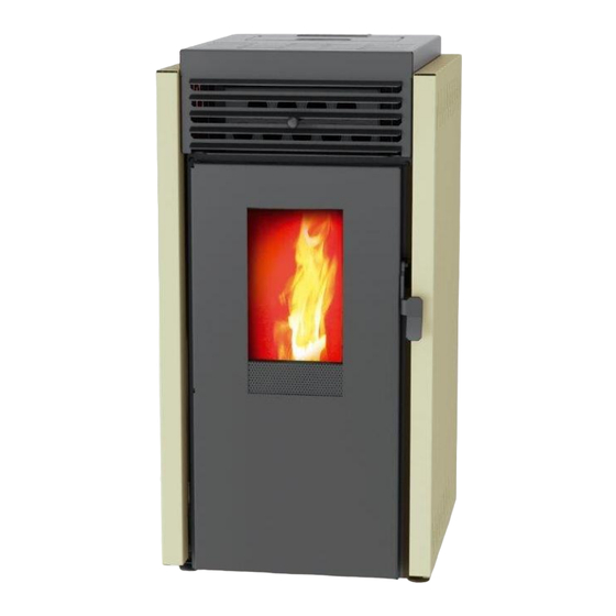
PELLET STOVE
6-8-10-12 KW
USER AND INSTALLATION MANUAL
LASIAN Heat Technology S.L.
Table of
Contents
Previous
Page
Next
Page
1
2
3
4
5
Advertisement
Table of Contents
Need help?
Do you have a question about the AUDAX 6 KW and is the answer not in the manual?
Ask a question
Questions and answers
Related Manuals for LASIAN AUDAX 6 KW
Pellet stove LASIAN AUDAX 8 KW User And Installation Manual
Up to 12kw (48 pages)
Pellet stove LASIAN AUDAX 10 KW User And Installation Manual
Up to 12kw (48 pages)
This manual is also suitable for:
Audax 8 kw
Audax 10 kw
Audax 12 kw
Table of Contents
Print
Rename the bookmark
Delete bookmark?
Delete from my manuals?
Login
Sign In
OR
Sign in with Facebook
Sign in with Google
Upload manual
Upload from disk
Upload from URL


Need help?
Do you have a question about the AUDAX 6 KW and is the answer not in the manual?
Questions and answers