
Related Manuals for Atmos S 351


Summary of Contents for Atmos S 351
- Page 1 English ® ATMOS S 351 444.0405.B 2017-07 Index: 25 ATMOS MedizinTechnik Ludwig-Kegel-Str. 16 Tel. +49 (0) 7653 / 6 89-0 atmos@atmosmed.de GmbH & Co. KG 79853 Lenzkirch / Germany Fax +49 (0) 7653 / 6 89-190 www.atmosmed.de...
-
Page 2: Table Of Contents
Contents Page Introduction Spare parts and accessories Notes on operating instructions ......3 Spare parts ..........37 - 38 Function ..............4 Accessories ..........39 - 41 Explanation of symbols .........5 9.2.1 Canisters and hoses ...........39 9.2.2 Accessories to simplify handling ......40 Safety information ........ -
Page 3: Introduction
Major maintenance and repair work must be carried out only by experts authorised by ATMOS. Please insist that only origi- nal spare parts are used for repairs. This will guarantee that operational safety, usability and value of your equipment are preserved. -
Page 4: Function
The ATMOS ® S 351 produces this vacuum with the aid of a microprocessor- based controller. The pump switches off when the set value is reached. A control circuit ensures that the pump only runs when the vacuum is less than the value set. -
Page 5: Explanation Of Symbols
1.0 Introduction Explanation of symbols Caution, observe operating instructions ! Equipment safety fuse Unit off Unit on Fine suction "limit" "max." Maximum vacuum Standby function ON/OFF Alternating current Protective ground terminal Trolley Foot regulator Filter blocked Full secretion canister Bacterial fi lter Equipotential bonding Application part Type B... -
Page 6: Safety Information
The doctor treating the patient is responsible for the proper The ATMOS S 351 must only be operated in rooms ® surgical procedures and technology. A trained doctor has to designated for medical use. It is not designed for use in... - Page 7 Prior to and during the wound drainage treatment, make If the fi nal vacuum set is not achieved, the ATMOS ® sure that the connection hoses are not kinked or clog- 351 Natal will not issue an audible signal „fi nal vacuum ged.
-
Page 8: Intended Use
3.0 Intended Use Name: ATMOS S 351 ® Main functions: Suction of secretions, rinsing fl uids and temporarily collection of body fl uids. Med. indications/ application: For surgeries e.g. suction of wound cavities, abscesses etc. For endoscopy e.g. suction of secretions and rinsing fl uids. -
Page 9: Installation And Comissioning
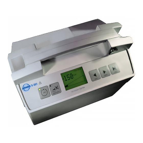
Indicators and controls Fig. 1. ATMOS S 351 ® Bracket and contact element for secretion canister Pump connection Safety secretion canister with optional fi lter Bracket for secretion canister ... - Page 10 REF 000.0239.0 nected to the bacterial fi lter The suction device ATMOS S 351 is used for sucking off liquids ® and small particles. During the use of laser, HF respectively radio- frequency (RF) surgical devices, smoke gas is produced which is not kept in the secretion container, but streams towards the pump and then very quickly blocks the integrated bacterial fi...
-
Page 11: Initial Start-Up
– how to lock and insert the secretion canister, – which hoses have to be connected, – how to connect the ATMOS S 351 to mains electricity. ® Please note the safety information in Section 2.0 ... - Page 12 Fig. 5. Please do not use the secretion canister brackets on the ATMOS S 351 and the trolley ® for any other purposes. This will prevent malfunctions. Fig. 5. Attaching the 1.5 litre secretion canister ...
- Page 13 safety canister lid The ATMOS S 351 must never be used without a ® bacterial fi lter. Fig. 8. Hose connections for suction mode Pump connection Bacterial fi lter Safety canister lid ...
- Page 14 4.0 Installation and commissioning Now fi t the suction hose to the angled connection of the double connecting nipple. Fig. 9. Connecting the suction hose The 10 mm dia. suction hose is fi tted directly to connec- (...
- Page 15 connection If you have a footswitch, connect it to its connection , Fig. 11). The ATMOS S 351 is now ready for operation. ® Fig. 11. ...
-
Page 16: Operation
A suction catheter, a suction connector or medical suction instruments must always be used. Basic Operation Switching on The ATMOS S 351 always starts the suction process when ® switched on. The settings are those which were in operation ... -
Page 17: 5.0 Operation
Electronic fi lling level monitoring The ATMOS S 351 has an electronic fi lling level monitoring ® which switches off the unit when the maximum fi lling level is reached. At the same time, an audible alarm sounds and the Secretion canister full display is shown (Fig. -
Page 18: Intermittent Function
0 sec. 5.2.2 Starting the intermittent mode Switch on the ATMOS S 351. Check that the control lamp ® in the switch is illuminated. The switch-on menu (Fig. 17) is shown on the display for about 2 sec. -
Page 19: 5.0 Operation
5.0 Operation Press the intermittent button (Fig. 18). Fig. 18. The intermittent mode is obtained by pressing the intermittent button. The unit automatically changes into intermittent mode and starts with phase 1: soft start (Fig. 19). The current phase (phase 1 = 1, phase 2 = 2, …) and the time remaining (in seconds) to the end of the current phase are displayed at the top left. -
Page 20: 5.0 Operation
3 is shown at the top left (in the example it is 7 sec). In phase 4, the ATMOS S 351 pauses at a vacuum of 0 kPa ® (Fig. 22). Display of Phase 4: The vacuum has been com- Fig. -
Page 21: Additional Functions
Additional functions During intermittent mode, it is possible to change the fi nal vacuum of the ATMOS S 351 using the arrow buttons (Fig. 24). ® Using the arrow buttons (, , MAX) The arrow buttons have the following functions in intermittent mode: ... -
Page 22: Warning Signals
5.0 Operation 5.2.5 Warning signals Electronic level monitor: See page 17 Short circuit between contact terminals: In case of a short circuit between the contact terminals, a warn- ing is displayed at regular intervals (Fig. 24, page 20). At the same time an audible alarm sounds. -
Page 23: Final Vacuum In Vac Limit Menu
5.0 Operation 5.3.1 Final vacuum in Vac Limit menu Select the Adjust intermittent menu from the Service 1 menu (Fig. 27) using the arrow buttons. The Adjust intermittent menu (Fig. 28) is called up by pressing the MAX button. ... -
Page 24: Vacuum Holding Period In The Vac Hold Menu
5.0 Operation 5.3.3 Vacuum holding period in the Vac hold menu Select the Adjust intermittent menu from the Service 1 menu (Fig. 27, page 22) using the arrow buttons. The Adjust intermittent menu (Fig. 28, page 22) is called up by pressing the MAX button. -
Page 25: Adjust Unities
Adjust unities The vacuum unity displayed can be changed for the ATMOS ® adjust unity S 351. To do this, press and hold the Auto Standby button while switching on until Service-1 is displayed on the graph- ics display. ... -
Page 26: Suction Function
, Fig. 34) . The ATMOS S 351 starts up and begins to generate the ® vacuum. The vacuum reached at any time is displayed. The unit switches off when the fi nal vacuum is reached. If the vacuum... -
Page 27: Changing The Secretion Canister
Insert the double connecting nipple into the empty secretion canister and continue suction. After use Switch off the ATMOS S 351 and clean unit and accessories ® as described in chapter 6.0. Fig. 37. Removing the secretion canister... -
Page 28: Suction With Footswitch
ATMOS S 351. Please call the service ® department if this happens. The ATMOS® S 351 functions are restricted in this case. Control of the vacuum is no longer possible. The following functions are still available: Fig. 39. Display for emergency operation ... -
Page 29: Overheating
5.0 Operation 5.6.2 Overheating The ATMOS S 351 is designed for continuous operation. If the ® ventilation louvres are blocked, the unit may overheat. Initially, a warning is given (graphics display fl ashes): Check the ventilation louvres of the ATMOS S 351. -
Page 30: Cleaning And Maintenance
6.0 Cleaning and Maintenance Reprocessing of hoses and secretion canister Always wear protective clothing (gloves) when carrying out cleaning work. Those parts which come into contact with the secretion must be cleaned and disinfected after each use before a new patient is treated. -
Page 31: Cleaning And Disinfecting The Outside Of The Unit
6.0 Cleaning and Maintenance Cleaning and disinfecting the outside of the unit You must disconnect the mains plug before cleaning and disinfecting the unit casing. Wipe over the casing with a cloth moistened with a cleaning agent or disinfectant solution. Do not allow any liquid to enter the equipment. -
Page 32: Recommended Instrument Disinfectants
6.0 Cleaning and Maintenance Recommended instrument disinfectants Disinfectant Contents (in 100 g) Manufacturer GIGASEPT FF succinic acid dialdehyde Schülke & Mayr, Norderstedt (concentrate) Dimethoxytetrahydrofurane Corrosion protection agents non-ionic tensides and perfume neodisher MediClean forte non-ionic tensides < 5 Dr. Weigert, Hamburg (application concentrate) NTA (nitrilotriacetic acid) 5-15... -
Page 33: Maintenance
Airtight packing Please enclose a detailed error description. Warranty ATMOS cannot guarantee an error-free function nor can ATMOS be held liable for damage to people or goods if non-original ATMOS parts are used, the information in these operating instructions are disregarded, ... -
Page 34: Trouble-Shooting
8.0 Trouble-shooting Please clean your ATMOS S 351 before sending ® This section describes how to remove functional faults. in for servicing. Remedies Fault Possible cause Unit does not start up – Mains plug not inserted properly – Check mains plug (indicator light in switch not illuminated) –... - Page 35 Chapter 5.3.6 – If the display clears, the ATMOS ® Spanner displayed on graphics – An equipment fault has occurred 351 was able to remove the fault.
- Page 36 ® (bottom of unit). They must not be has overheated) – Excessive ambient temperature blocked – Fan faulty – Only use the ATMOS S 351 within ® the temperature range stated. Try and use auto standby (less heat is generated) –...
-
Page 37: Spare Parts And Accessories
9.0 Spare Parts and Accessories Spare Parts Description Safety canister, standard (without fi lter, without lid) ......000.0504.0 Safety canister, compl. with fi lter ....444.0080.0 Silicone hose - f. safety canister - secretion canister ...443.0046.0 - f. connecting nipple - fi lter......320.0044.0 - f. - Page 38 9.0 Spare Parts and Accessories Description Double connecting nipple, compl....444.0012.0 O-ring 6 mm dia. (at least 5 pcs.) ....055.0069.0 Hose reducer ..........444.0013.0 O-ring 23 mm dia. (at least 5 pcs.) ....055.0073.0 O-ring 14 mm dia. (at least 5 pcs.) ....055.0072.0 Contact spring washer ........444.0079.0 Spare parts (not shown) Fuse 230 V T 1 A/H ..........008.0471.0...
-
Page 39: Accessories
9.0 Spare Parts and Accessories Accessories 9.2.1 Canisters and hoses Description Secretion canister, glass, with graduation 1.5 l ........... 444.0032.0 Secretion canister, glass, with graduation 3 l ..........444.0033.0 Secretion canister, glass, with graduation 5 l ..........444.0034.0 Secretion canister, polysulfone, 1.5 l ............444.0036.0 Secretion canister, polysulfone, 3 l .............. -
Page 40: Accessories To Simplify Handling
9.0 Spare Parts and Accessories 9.2.2 Accessories to simplify handling Description Hose bracket, for attachment on unit or trolley ..........444.0450.0 Trolley with antistatic castors (for surgery) ..........444.0020.0 Trolley (for obstetrics); kit (does not provide electronic overfl ow monitor facility) ......... 320.0070.0 Foot regulator, electronic, waterproof IP X8, AP protected ...... -
Page 41: Cannulae, Cardiovascular/Thoracic Surgery
9.0 Spare Parts and Accessories 9.2.4 Cannulae, Cardiovascular/Thoracic Surgery Description Cooley OP suction cannula L = 350 mm ..........401.0612.0 9.2.5 Cannulae, ENT Frazier ENT cannula 8 CH ................ 401.0606.0 Frazier ENT cannula 10 CH ..............401.0607.0 with suction interruption opening 9.2.6 Aesthetic / Plastic Surgery See separate brochure! -
Page 42: Technical Specifi Cations
10.0 Technical specifi cations Air fl ow rate 36 ± 2 l/min. -90 kPa** Max. vacuum Digital numeric, resolution 10 mbar / 10 mmHg / 1 kPa Vacuum readout and quasi analog via bar graph; accuracy ± 2% Electronically controlled magnetic valve Auxiliary air control Up to -0.3 bar (can be set between -0.2 bis -0.5 bar by service engineer) Fine- suction... -
Page 43: Technical Specifi Cations
10.0 Technical specifi cations All values are quoted with a tolerance of ± 5 %,unless separately specifi ed. * NN ≅ 1013 mbar ambient pressure ** 1 bar ≅ 750,06 mm Hg ≅ 1000 hPa / dependent on daily air pressure Canadian Classifi... -
Page 44: Disposal
ATMOS MedizinTechnik GmbH & Co. KG for a professional disposal. Prior to disposal respectively before transport all secretion canisters and tubes must be removed. -
Page 45: Notes On Emc
12.1 Guidelines and Manufacturer´s Declaration - Emissions The ATMOS S 351 is intended for use in the electromagnetic environment specifi ed below. The customer or user of ® the ATMOS S 351 should ensure that it is used in such an environment. - Page 46 12.3 Guidelines and Manufacturer´s Declaration - Immunity The ATMOS S 351 is intended for use in the electromagnetic environment specifi ed below. The customer or user of ® the ATMOS S 351 should ensure that it is used in such an environment.
-
Page 47: Notes On Emc
ATMOS ® S 351 The ATMOS S 351 is intended for use in electromagnetic environment in which radiated disturbances are con- ® trolled. The customer or user of the ATMOS S 351 can help prevent electromagnetic interference by maintai- ®... - Page 48 ATMOS MedizinTechnik GmbH & Co. KG in accepting such goods or payment arrears. Acts of God or stoppages upon in writing by us.
Need help?
Do you have a question about the S 351 and is the answer not in the manual?
Questions and answers