Sign In
Upload
Download
Table of Contents
Contents
Add to my manuals
Delete from my manuals
Share
URL of this page:
HTML Link:
Bookmark this page
Add
Manual will be automatically added to "My Manuals"
Print this page
×
Bookmark added
×
Added to my manuals
Manuals
Brands
GE Manuals
Relays
P741
Technical manual
GE P741 Technical Manual
Busbar differential protection relay
Hide thumbs
1
2
3
4
5
6
7
8
9
10
11
12
13
14
15
16
17
18
19
20
21
22
23
24
25
26
27
28
29
30
31
32
33
34
35
36
37
38
39
40
41
42
43
44
45
46
47
48
49
50
51
52
53
54
55
56
57
58
59
60
61
62
63
64
65
66
67
68
69
70
71
72
73
74
75
76
77
78
79
80
81
82
83
84
85
86
87
88
89
90
91
92
93
94
95
96
97
98
99
100
101
102
103
104
105
106
107
108
109
110
111
112
113
114
115
116
117
118
119
120
121
122
123
124
125
126
127
128
129
130
131
132
133
134
135
136
137
138
139
140
141
142
143
144
145
146
147
148
149
150
151
152
153
154
155
156
157
158
159
160
161
162
163
164
165
166
167
168
169
170
171
172
173
174
175
176
177
178
179
180
181
182
183
184
185
186
187
188
189
190
191
192
193
194
195
196
197
198
199
200
201
202
203
204
205
206
207
208
209
210
211
212
213
214
215
216
217
218
219
220
221
222
223
224
225
226
227
228
229
230
231
232
233
234
235
236
237
238
239
240
241
242
243
244
245
246
247
248
249
250
251
252
253
254
255
256
257
258
259
260
261
262
263
264
265
266
267
268
269
270
271
272
273
274
275
276
277
278
279
280
281
282
283
284
285
286
287
288
289
290
291
292
293
294
295
296
297
298
299
300
301
302
303
304
305
306
307
308
309
310
311
312
313
314
315
316
317
318
319
320
321
322
323
324
325
326
327
328
329
330
331
332
333
334
335
336
337
338
339
340
341
342
343
344
345
346
347
348
349
350
351
352
353
354
355
356
357
358
359
360
361
362
363
364
365
366
367
368
369
370
371
372
373
374
375
376
377
378
379
380
381
382
383
384
385
386
387
388
389
390
391
392
393
394
395
396
397
398
399
400
401
402
403
404
405
406
407
408
409
410
411
412
413
414
415
416
417
418
419
420
421
422
423
424
425
426
427
428
429
430
431
432
433
434
435
436
437
438
439
440
441
442
443
444
445
446
447
448
449
450
451
452
453
454
455
456
457
458
459
460
461
462
463
464
465
466
467
468
469
470
471
472
473
474
475
476
477
478
479
480
481
482
483
484
485
486
487
488
489
490
491
492
493
494
495
496
497
498
499
500
501
502
503
504
505
506
507
508
509
510
511
512
513
514
515
516
517
518
519
520
521
522
523
524
525
526
527
528
529
530
531
532
533
534
535
536
537
538
539
540
541
542
543
544
545
546
547
548
549
550
551
552
553
554
555
556
557
558
559
560
Table Of Contents
561
page
of
561
Go
/
561
Contents
Table of Contents
Troubleshooting
Bookmarks
Table of Contents
Table of Contents
P74X/En It/Na7
Documentation Structure
Introduction to the Unit
Functional Overview
Product Scope
Figure 1: Functional Diagram
Ordering Options
P74X/En Td/Na7
Technical Data
Mechanical Specification
Enclosure Protection
Terminals Data
Ratings
Transmitter Optical Characteristics
Power Supply
Operating Range
Output Contacts
Environmental Conditions
Type Tests
Electromagnetic Compatibility (EMC)
Mechanical Robustness
IRIG-B and Real Time Clock
Dead Zone Protection
Busbar Protection
Performance Data
Protection Functions
Ethernet Data
Current Transformer and Feeder Characteristics
Dead Zone Protection (PU)
Breaker Failure Protection (PU)
Overcurrent Protection (PU)
Configuration
Earth Fault Protection (50N/51N)
Date and Time
CB Control (PU)
Measurements and Records List
Communications
Oscillography (Disturbance Recorder)
Optional Ethernet Port
Commission Tests
P74X/En Gs/Na7
Front Panel
Getting Started
User Interfaces and Menu Structure
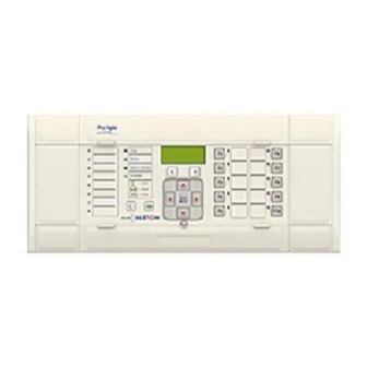
Figure 2: Relay Front View (Example for P743 – 60 Te)
LED Indications
The Default Mappings for each of the Programmable Leds
Relay Rear Panel
Figure 4: P743 Relay Rear View 60Te
Introduction to the User Interfaces and Settings Options
Relay Connection and Power-Up
Menu Structure
Control and Support Settings
Disturbance Recorder Settings
Password Protection
Protection Settings
Front Panel User Interface (Keypad and LCD)
Relay Configuration
Default Display and Menu Time-Out
Control Inputs – User Assignable Functions
Hotkey Menu Navigation
Menu Navigation and Setting Browsing
Setting Group Selection
Password Entry
Reading and Clearing of Alarm Messages and Fault Records
Front Communication Port User Interface
Setting Changes
Figure 9: Front Port Connection
Front Courier Port
S1 Agile Relay Communications Basics
Off-Line Use of S1 Agile
Configuring the Ethernet Interface
Configuring the Board IP Address
Configuring the IED IP Address
Configuring the Redundant Ethernet Board
RSTP Configuration
Device Identification
IP Address Configuration
SNTP IP Address Configuration
RSTP Parameters
Bridge Parameters
Port Parameters
Port States
Configuring the Data Protocols
Courier Configuration
IEC 61850 Configuration
IEC 61850 Configuration Banks
IEC 61850 Network Connectivity
Connecting the IED to a PC
Installing the Configurator
PRP/HSR Configurator
Starting the Configurator
Check for Connected Equipment
PRP Configuration
PRP/HSR IP Address Configuration
Selecting the Device Mode
Filtering Database
HSR Configuration
End of Session
Filtering Entries Tab
Goose Filtering Tab
P74X/En St/Na7
Settings
Relay Settings Configuration
“System Data” Column
Central Unit P741
“Configuration” Column (P741 Central Unit)
“Configuration” Column (P742 / P743 Peripheral Units)
“PU Conf & Status” Column (P741 Central Unit)
Default Settings Restore
“Date and Time” Column
Differential Phase Fault Configuration
Differential Protection Configuration
Sensitive Earth Fault Element
Busbar Trip (87Bb)/Central Breaker Fail Backtrip Confirmation (50BF)
Dead Zone Configuration
Non-Directional Phase Overcurrent Protection
Circuit Breaker Fail and Undercurrent Function
CT Supervision
Circuit Breaker Control
“CT and VT Ratios” Column
“Record Control” Column
Measurements (“Measure’t Setup” Column)
Courier Protocol
Ethernet Port
“Communications” Column
Rear Port 2 Connection Settings
“Commissioning Tests” Column
Opto Configuration (“Opto Config” Column)
Control Input Setting (“Control Input” Column)
Intermicom Communications
Control Input Configuration (“Ctrl I/P Config” Column)
“Intermicom Comm and Conf” Columns
Intermicom Configuration
“Function Keys” Menu
“IED Configurator” Column
“Control I/P (Input) Labels” Column
Disturbance Recorder Settings Tables
P74X/En Op/Na7
Operation
Operation of Individual Ptorection Functions
Busbar Biased Current Differential Protection
Application of Kirchoffs Law
Bias Characteristic and Differential Current
Scheme Supervision by "Check Zone” Element
Busbar Protection Operation
Bias Characteristic and Differential Current Setting
Scheme Earth Characteristic Element
Threshold Coherency
Signal Quality
Tripping Criteria
Trip Duration
Current Circuit Supervision
Protection Options for the Zones
Options for a Circuitry Fault
Options for a PU Error Mode
Protection Options for the Check Zone
Vt(S) Connected to the Line(S) and a Peripheral Unit
Vt(S) Connected to the Bar(S) and the Central Unit
Voltage Criteria for Busbar Protection
Busbar Protection Tripping Order PU Logic
Dead Zone Protection (DZ)
Stub Protection
Busbar Protection Tripping Time Delays
Overcurrent Criterion
Undercurrent Reset Criterion
Circuit Breaker Fail Reset Criteria
Circuit Breaker Fail (CBF)
Principle of the Undercurrent Function
CB Element Logic
Logic Reset Criterion
Logic and Current Reset Criterion
Processing a Circuit Breaker Failure Condition
CB Fail Logic
Internally Initiated CBF
Back-Trip after Time Tbf2
Initial Trip
Re-Trip after Time Tbf1
Description of the Logic for Internally Initiated CBF
Circuit Breaker Failure Logic
General Zone Trip after Time Tbf4
Externally Initiated 50BF
Local Re-Trip after Time Tbf3
Three Phase Overcurrent Protection
CB Fail Alarm
Separate External 50BF Protection to the Busbar Protection
Inverse Time (IDMT) Characteristic
Earth Fault Protection
EF Time Delay Characteristics
External Fault Detection by High-Set Overcurrent/Earth Fault Element
Zero Sequence Current Supervision
Intermicom Teleprotection Introduction
Protection Signaling
Definition of Teleprotection Commands
EIA(RS)232 Intermicom (“MODEM Intermicom”)
Communications Media
Pictorial Comparison of Operating Modes
General Features & Implementation
EIA(RS)232 Physical Connections
Direct Connection
Modem Connection
Functional Assignment
Intermicom Statistics & Diagnostics
Current Transformers
CT Saturation Detection
Current Variation
Determinatoin of Signal Quality in Peripheral Unit
CT Saturation Reset
CT Location
Isolator and Circuit Breaker Function
Isolator State Monitoring Features
Circuit Breaker State Monitoring Features
CB State Monitoring Features Diagram
Remote Control of Circuit Breaker Diagram
Differential Current Display
Operation of Non Protection Functions
IRIG-B Signal (P741) Only
Programmable Scheme Logic
Communications between PU and CU
Communications Link
Direct Optical Fibre Link, 850Nm Multi-Mode Fibre
Optical Budgets
Trip LED Logic
Function Keys
CB Control Using Hotkeys
CB Control Hotkey Menu Diagram
CB Control Via Function Keys Default PSL Diagram
CB Control Using Function Keys
Setting Groups Selection
Control Inputs
P74X/En Ap/Na7
Application Notes
Protection of Substation Busbars
87BB Phase CU Settings (Solid Earthed Network Schemes)
Application of Individual Protection Functions
Busbar Protection Setting Guidelines
Sub-Station Features
“Idiff_Ibias” Setting Calculation Spreadsheet
Differential Busbar Protection
87BB CU Settings (Compensated Earthed Network Schemes)
87BB SDEF CU Settings (High Impedance Earthed Schemes Only)
Sub-Station Features - 8 Values
“Idiff_Ibias_Sdef_Highimp” Setting Calculation Spreadsheet
SDEF Busbar Protection
Busbar Protection Tripping Times
Busbar Protection Tripping Time Delay in a PU
Busbar Protection Tripping Time Delay in the CU
Over Current Protection (OC)
Earth Fault Protection (EF)
Transformer Feeder Example
CT Features
Setting Guidelines
Current Transofmers
“Low Voltage” Current Transformers Supervision
“High Voltage” Current Transformers Supervision
Circuit Breaker Function
Circuit Breaker State Monitoring
Trip Relays and Trip Circuit Supervision
TCS Scheme
Scheme 1 Optional R1 Opto Input Resistor Values
Scheme 1 PSL
TCS Scheme 2
Scheme 2 PSL
Scheme 3 Optional R1, R2 & R3 Opto Input Resistor Values
TCS Scheme 3
Scheme 3 PSL
CB Failure Protection (50BF) Disabled
Peripheral Units (P742 and P743)
Isolation and Reduced Function Mode
PU - Overhaul
Forcing Plant Position State
Central Processing Unit
Busbar Protection (87BB) Blocked
87BB Blocked & 50BF Disabled
System Operation under Failed Communications Situation
Waiting Configuration
Topology
Topology Configuration Tool
Nodal Assignment
Topology Communication
Topology Data
Topology Processing
Single Bar or Double Bus with Bus Sectionaliser
Double Bus with One CT Bus Coupler
Double Bus with Two CT Bus Coupler
Cts on One Side of Bus Coupler, CB Closes before Status Acquisition
Cts on One Side of Bus Coupler/Cb Closed/Fault Evolves between CT, CB
Cts on both Sides of Bus Coupler, CB Closes before Status Acquisition
Cts on both Sides of Coupler/Cb Closed/Fault Evolves between CT and CB
Undertaking a Numerical Differential Busbar Protectin Project
General Substation Information
Short Circuit Levels
Switchgear
Cubicle Specifications
Substation Architecture
Single Busbar Application with Bus Section Isolator
Standard Configurations
Single Busbar Application with Bus Section Circuit Breaker
Breaker and a Half Scheme
Double Busbar Application with Bus Coupler
Traditional Double Busbar Application with Bus Coupler and Bus Section
Triple Busbar Application with Bus Coupler and Bus Section
Double Bus Bar with Two Circuit Breakers Per Feeder
Mesh Corner Diagram
Six Main Bus for S/S CB Bus-Sections and CB By-Pass
Application of Non Protection Functions
Commissioning Mode Default PSL
CT Requirements
87BB Phase CT Requirements
Feeders Connected to Sources of Significant Power
Out of Service Feeders or those with Low Power Contribution
CT Specification According to IEC 185, 44-6 and BS 3938
87BB Sensitive Differential Earth Fault CT Requirements
Support of IEEE C Class Cts
Auxiliary Supply Fuse Rating
Advertisement
Quick Links
1
Technical Data
Download this manual
GE Energy Connections
Grid Solutions
MiCOM P40 Agile
P741, P742, P743
Technical Manual
Busbar Differential Protection Relay
Hardware version: J and K
Software version: 51
Publication reference: P74x/EN M/Na7
Table of
Contents
Previous
Page
Next
Page
1
2
3
4
5
Advertisement
Table of Contents
Troubleshooting
Troubleshooting
452
Incorrect analog signals
472
Need help?
Do you have a question about the P741 and is the answer not in the manual?
Ask a question
Questions and answers
Related Manuals for GE P741
Relays GE P742 Technical Manual
Busbar differential protection relay (561 pages)
Relays GE P743 Technical Manual
Busbar differential protection relay (561 pages)
Relays GE L90 Instruction Manual
Ur series line current differential system (832 pages)
Relays GE L90 Instruction Manual
Line differential relay ur series (486 pages)
Relays GE G30 Instruction Manual
Generator protection system 7.6x (696 pages)
Relays GE B90 Instruction Manual
Ur series low impedance bus differential system (474 pages)
Relays GE T60 Instruction Manual
Transformer protection system ur series (771 pages)
Relays GE DGP Series Instruction Manual
Digital generator protection relay (278 pages)
Relays GE 750 Instruction Manual
Feeder management relay (334 pages)
Relays GE D90 Plus Communications Manual
Line distance protection system (222 pages)
Relays GE T35 Instruction Manual
Transformer protection system ur series (526 pages)
Relays GE B30 Communications Manual
Universal relay family (532 pages)
Relays GE P24DM Technical Manual
Motor protection ied (600 pages)
Relays GE 469 Instruction Manual
Motor management relay (336 pages)
Relays GE L30 Instruction Manual
Line current differential system ur series (698 pages)
Relays GE MiCOM P40 Technical Manual
P446sv (962 pages)
This manual is also suitable for:
P742
P743
Table of Contents
Save PDF
Print
Rename the bookmark
Delete bookmark?
Delete from my manuals?
Login
Sign In
OR
Sign in with Facebook
Sign in with Google
Upload manual
Upload from disk
Upload from URL


Need help?
Do you have a question about the P741 and is the answer not in the manual?
Questions and answers