Table of Contents
Advertisement
Quick Links
Advertisement
Table of Contents

Related Manuals for Westermo BRD-355A


Summary of Contents for Westermo BRD-355A
- Page 1 BRD-355A & BRD-355B Industrial ADSL/VDSL Routers...
- Page 2 6623-2232...
-
Page 3: General Information
Under no circumstances shall Westermo be responsible for any loss of data or income or any special, incidental, and consequential or indirect damages howsoever caused. -
Page 4: Safety And Regulations
Safety and Regulations Warning signs are provided to prevent personal injuries and/or damages to the product. The following levels are used: Level of warning Description Consequence Consequence personal injury material damage Indicates a potentially Possible death or Major damage to the hazardous situation major injury product... -
Page 5: Before Installation
WARNING - PROTECTIVE FUSE It must be possible to disconnect manually from the power supply. Ensure compliance to national installation regulations. Replacing the internal fuse must only be performed by Westermo qualified personell. WARNING - POWER SUPPLY CONNECTION There are safety regulations on which power sources that shall be used in conjunction with the product. - Page 6 WARNING - REDUCE THE RISK OF FIRE To reduce the risk of fire, use only telecommunication line cords with a cable diameter of AWG 26 or larger. Regarding power cable dimensions, see Interface Specifications. CAUTION - ELECTROSTATIC DISCHARGE (ESD) Prevent electrostatic discharge damages to internal electronic parts by discharging your body to a grounding point (e.g.
-
Page 7: Care Recommendations
If the product is used in a manner not according to specification, the protection provided by the equipment may be impaired. If the product is not working properly, contact the place of purchase, nearest Westermo distributor office or Westermo technical support. -
Page 8: Simplified Eu Declaration Of Conformity
Simplified EU declaration of conformity Hereby, Westermo declares that the product is in compliance with applicable EU directives. The full EU declaration of conformity and other detailed information is available at the respective product page at www.westermo.com/support/product- support. Agency approvals and standards compliance... -
Page 9: Type Tests And Environmental Conditions
Type tests and environmental conditions Phenomena Test Description Test levels EN 61000-4-2 Enclosure contact ± 6 kV (crit B) Enclosure air ± 8 kV (crit A) Radiated RF immunity IEC 61000-4-3 Enclosure 20 V/m (crit A) (80 – 6000 MHz) Fast transient EN 61000-4-4 DC power ports... - Page 10 BRD-355 includes a wide feature set for various legacy applications including both modem replacement methods as well as serial to Ethernet conversion. If there are applications that require extra attention Westermo's extensive experience from over 35 years within industrial data communications and over 5 years of industrial xDSL expertise will be available to assist you.
-
Page 11: Interface Specifications
Interface specifications Power Rated voltage 12 – 48 VDC Operating voltage 10 – 60 VDC Operational current (max) 450 mA @ 12 VDC Rated current (max) 1000 mA @ 12 VDC Rated frequency* Startup current 2 x rated current Circuit type SELV/ES1 Cable size 0.2-2.5 mm²... - Page 12 Protocol LLC/VC-MUX encap Ethernet, PPPoA, PPPoE, IPoA Connection 1 x RJ-11 Technology Annex/Profile BRD-355A BRD-355B BRD-355A-AU TI.413 • • ADSL • • ADSL • G.Lite • • ADSL2 • • ADSL2 • ADSL2 • ADSL2 • • ADSL2 • •...
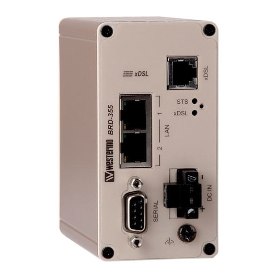
- Page 13 Connections DSL-connection Ethernet TX Connections Factory default reset switch (RJ-45 connector) LAN1-2 Position Direction Description In/Out In/Out TD– Led indicators In/Out – Not Connected – Not Connected Protective Earth In/Out RD– – Not Connected – Not Connected Router Serial Port (DCE Female) Position Name Direction...
-
Page 14: Led Indicators
LED Indicators Status Description Indicates a fault, except during boot-up Status RED FLASH Indicates a fault, except during boot-up GREEN All OK GREEN & ONE RED FLASH All OK but no VPN peer connected No ADSL connection xDSL Link status GREEN FLASH Negotiating with the provider DSLAM GREEN... -
Page 15: Factory Default Reset Switch
Factory Default Reset Switch The reset switch is used to restore the configuration of the BRD-355 to the factory default settings (for details about the default settings see the Getting started section). The switch is accessed through a small hole, adjacent to the xDSL and STS LEDs, labeled C on the front of the unit. - Page 16 Protocols and Functionality Ethernet Technologies IEEE 802.3 for 10BaseT IEEE 802.3u for 100BaseTX Layer-2 QoS IEEE 802.1p Class of Service xDSL Technologies RFC2684 Bridged LLC and Bridged VC-MUX ATM encap. (ADSL) TR-067 Compliance Dying Gasp support ITU K.21 Support Rate adaptive modem at 32 Kbps steps ATM Layer with traffic shaping QoS support (UBR, CBR, VBR-rt,VBR-nrt) AAL5 –...
-
Page 17: Getting Started
Getting started Power Supply The BRD-355 requires a DC power source in the voltage range of 10 to 60 VDC. The unit is designed to self protect from permanent damage if the voltage exceeds 60 VDC or if reverse polarity is applied. The router may need to be returned for service if this occurs. - Page 18 • A login box will popup. If the box fails to display, re-check the cable connections to the unit and the IP address settings of the PC. Enter the following login details: • User Name: admin • Password: westermo 6623-2232...
- Page 19 • The Status summary page will be displayed, it will be similar to Figure 3. Figure 3 Note: If the unit is not yet configured it is likely that the Network Status and Connection Status will indicate a fault condition. This is normal. 6623-2232...
- Page 20 Mounting This unit should be mounted on 35 mm DIN-rail, which is horizontally mounted inside an apparatus cabinet or similar. Snap on mounting, see figure. Mounting the BRD-355 with integrated DIN-clip: Cooling 10mm 10mm This product uses convection cooling. To avoid obstructing the airflow around the product, use the following spacing rules.
-
Page 21: Dimensional Drawing
Dimensional drawing Measurements are stated in millimeters. 92.3 92.3 6623-2232... - Page 22 Westermo • SE-635 35 Stora Sundby, Sweden Tel +46 16 42 80 00 Fax +46 16 42 80 01 E-mail: info@westermo.com www.westermo.com REV. A 6623-2233 2021-03 Westermo Network Technologies AB, Sweden...
Need help?
Do you have a question about the BRD-355A and is the answer not in the manual?
Questions and answers